MX10008 Site Preparation Overview
MX10008 Site Preparation Checklist
The checklist in Table 1 summarizes the tasks you need to perform when preparing a site for an MX10008 installation.
✓ |
Item or Task |
For More Information |
|---|---|---|
| Environment | ||
□ |
Verify that environmental factors such as temperature and humidity do not exceed router tolerances. |
|
| Power | ||
□ |
Measure the distance between external power sources and the router installation site. |
|
□ |
Calculate the power consumption and requirements. |
|
| Rack | ||
□ |
Verify that your rack meets the minimum requirements for the installation of the router. |
|
□ |
Plan rack location, including required space clearances. |
MX10008 Depth Clearance Requirements for Airflow and Hardware Maintenance |
□ |
Secure the rack to the floor and building structure. |
|
| Cables | ||
□ |
Acquire cables and connectors:
|
The list of supported transceivers for the MX10008 line cards is located at MX10008 Transceivers and Specifications |
□ |
Plan the cable routing and management. |
|
□ |
Hardware Upgrades | Order upgrade kits or individual components. See MX10008 Components and Configurations. |
See Also
MX10008 Environmental Requirements and Specifications
The MX10008 router must be installed in a four-post rack. It must be housed in a dry, clean, well-ventilated, and temperature-controlled environment.
Follow these environmental guidelines:
The site must be as dust-free as possible, because dust can clog air intake vents and filters, reducing the efficiency of the router cooling system.
Maintain ambient airflow for normal router operation. If the airflow is blocked or restricted, or if the intake air is too warm, the router might overheat, leading to the router temperature monitor shutting down the device to protect the hardware components.
Table 2 provides the required environmental conditions for normal router operation.
Description |
Tolerance |
|---|---|
Altitude |
No performance degradation up to 6000 feet (1829 meters). |
Relative humidity |
Normal operation ensured in relative humidity range of 5% through 90%, noncondensing.
|
Temperature |
|
Seismic |
Designed to comply with Zone 4 earthquake requirements per NEBS GR-63-CORE, Issue 3. |
Install MX10008 router only in restricted areas, such as dedicated equipment rooms and equipment closets, in accordance with Articles 110-16, 110-17, and 110-18 of the National Electrical Code, ANSI/NFPA 70.
See Also
General Site Guidelines
This topic applies to hardware devices in the MX10008 routers.
Efficient device operation requires proper site planning and maintenance and proper layout of the equipment, rack or cabinet (if used), and wiring closet.
To plan and create an acceptable operating environment for your device and prevent environmentally caused equipment failures:
Keep the area around the chassis free from dust and conductive material, such as metal flakes.
Follow prescribed airflow guidelines to ensure that the cooling system functions properly and that exhaust from other equipment does not blow into the intake vents of the device.
Follow the prescribed electrostatic discharge (ESD) prevention procedures to prevent damaging the equipment. Static discharge can cause components to fail completely or intermittently over time.
Install the device in a secure area, so that only authorized personnel can access the device.
See Also
Site Electrical Wiring Guidelines
Table 3 describes the factors you must consider while planning the electrical wiring at your site.
It is particularly important to provide a properly grounded and shielded environment and to use electrical surge-suppression devices.
Site Wiring Factor |
Guideline |
|---|---|
Signaling limitations |
To ensure that signaling functions optimally:
|
Radio frequency interference (RFI) |
To reduce or eliminate the emission of RFI from your site wiring:
|
Electromagnetic compatibility (EMC) |
Provide a properly grounded and shielded environment and use electrical surge-suppression devices. Strong sources of electromagnetic interference (EMI) can cause the following damage:
Tip:
If your site is susceptible to problems with EMC, particularly from lightning or radio transmitters, you might want to seek expert advice. |
The intrabuilding port(s) of the equipment or subassembly is suitable for connection to intrabuilding or unexposed wiring or cabling only. The intrabuilding port(s) of the equipment or subassembly MUST NOT be metallically connected to interfaces that connect to the OSP or its wiring. These interfaces are designed for use as intrabuilding interfaces only (Type 2 or Type 4 ports as described in GR-1089-CORE), and require isolation from the exposed OSP cabling. The addition of primary protectors is not sufficient protection to connect these interfaces metallically to OSP wiring
MX10008 Rack Requirements
The MX10008 router chassis are designed to be installed in four-post racks.
Rack requirements consist of:
Rack type
Mounting bracket hole spacing
Rack size and strength
Rack connection to the building structure
Table 4 provides the rack requirements and specifications for the MX10008 router .
Rack Requirement |
Guidelines |
|---|---|
Rack type: four-post |
Use a four-post rack that provides bracket holes or hole patterns spaced at 1 U (1.75 in. or 4.45 cm) increments and that meets the size and strength requirements to support the weight. A U is the standard rack unit defined in Cabinets, Racks, Panels, and Associated Equipment (document number EIA-310–D) published by the Electronics Industry Association. You can stack three MX10008 routers if:
|
Rack mount kit hole spacing |
The holes in the rack mount kit are spaced at 1 U (1.75 in. or 4.45 cm), so that the router can be mounted in any rack that provides holes spaced at that distance. |
Rack size and strength |
|
Rack connection to building structure |
|
See Also
MX10008 Depth Clearance Requirements for Airflow and Hardware Maintenance
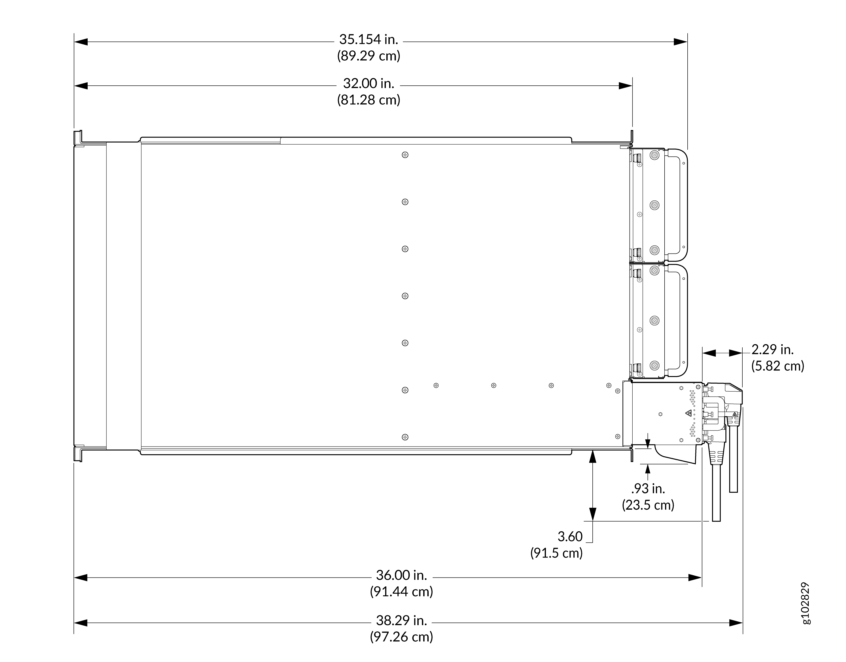
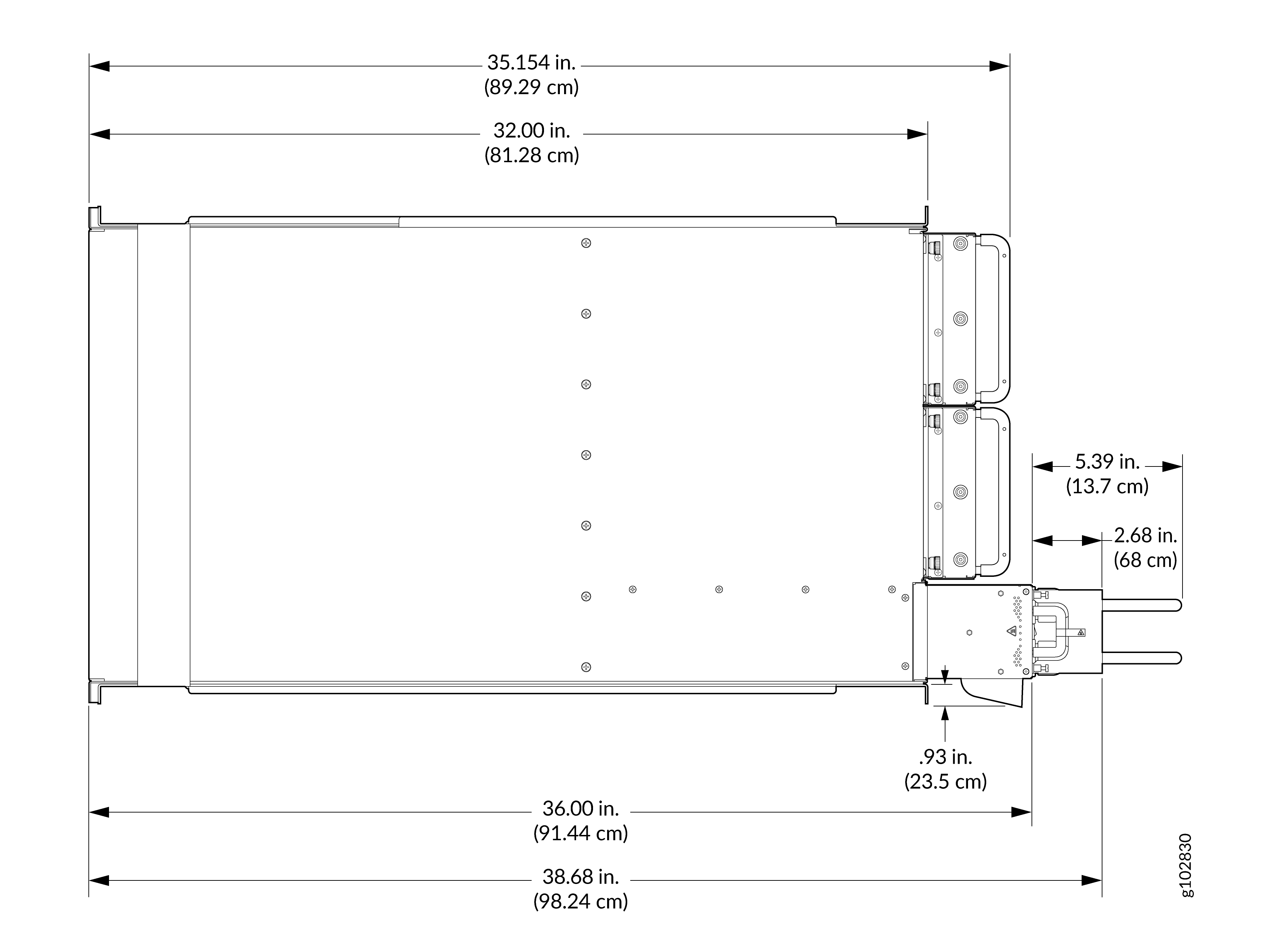
When planning the site for an MX10008 router installation, you must allow sufficient clearance around the installed chassis for cooling and maintenance (see Figure 1 for MX10008.
A minimum of half-an-inch clear space from the bottom of the chassisis is required for easy removal and insertion of the fan tray.
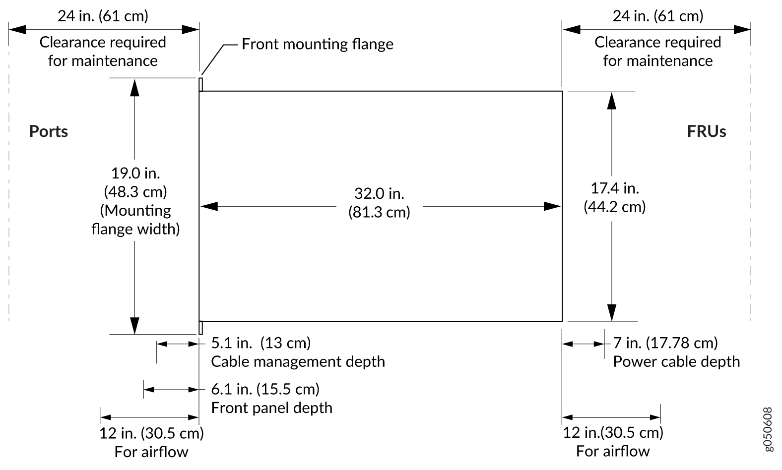
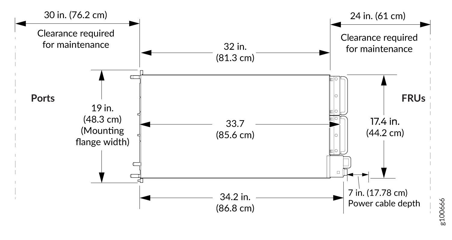
Leave at least 12 in. (30.5 cm) clearance in front and behind the chassis for airflow.
For JNP10K-PWR-AC3 power supply, the overall depth is 36 in. (91.44 cm) instead of 34.2 in. and the power cable depth is 6 in. (15.24 cm) instead of 7 in.
Follow these guidelines:
-
For the cooling system to function properly, the airflow around the chassis must be unrestricted. See MX10008 Cooling System and Airflow for more information about the airflow through the chassis.
-
If you are mounting an MX10008 router in a rack with other equipment, ensure that the exhaust from other equipment does not blow into the intake vents of the chassis.
-
Leave at least 24 in. (61 cm) both in front of and behind the MX10008 for service personnel to remove and install hardware components. To be NEBS GR-63 compliant, allow at least 30 in. (76.2 cm) in front of the rack and 24 in. (61 cm) behind the rack.