MX10008 Routing and Control Board Components and Descriptions
MX10008 Routing and Control Board Description
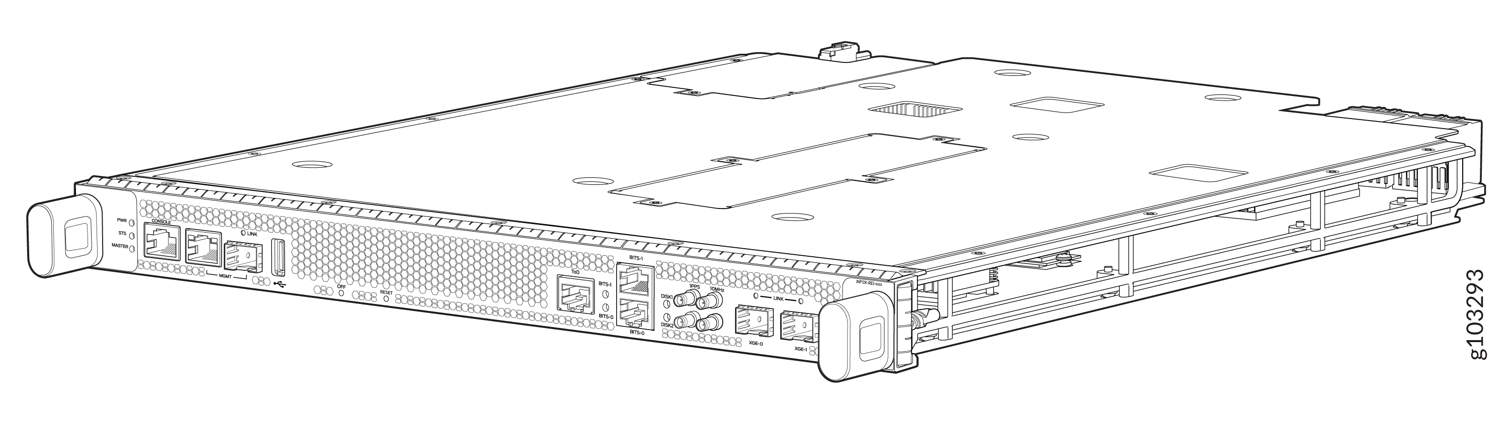
The MX10008 Routing and Control Board (RCB) is responsible for system management in an MX10008 router (see Figure 3). The chassis can run with one or two RCBs. The base configuration ships with one RCB while a redundant configuration ships with two RCBs. When two RCBs are installed, one functions as the primary and the second as a backup. If the primary RCB is removed, the backup becomes the primary if graceful Routing Engine switchover (GRES) is configured.
MX10008 supports the following Routing Engines:
-
JNP10K-RE3, 128 gigabytes of memory
-
JNP10K-RE3-LT, 128 gigabytes of memory
-
JNP10K-RE3-256, 256 gigabytes of memory
-
JNP10K-RE3LT256, 256 gigabytes of memory
-
JNP10K-RE1
-
JNP10K-RE1-LT
-
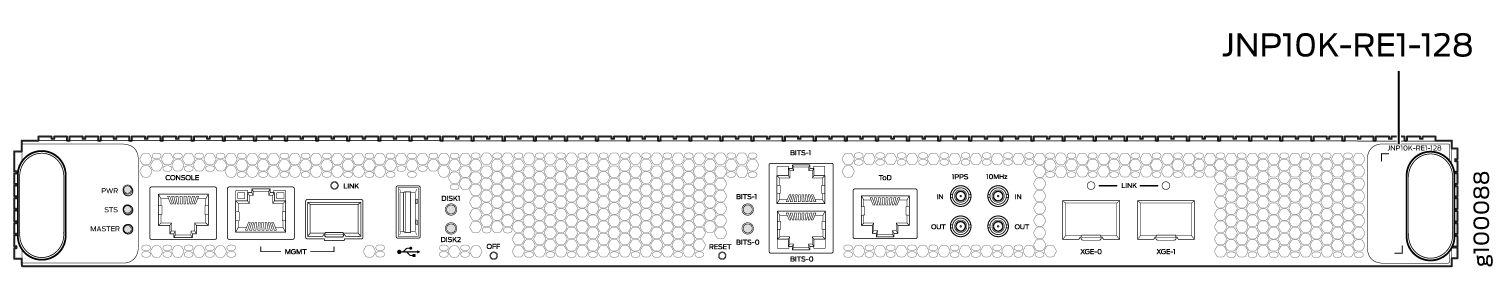
JNP10K-RE1-128
All the four variants of JNP10K-RE3 (JNP10K-RE3, JNP10K-RE3-LT, JNP10K-RE3-256, and JNP10K-RE3LT256) have the same form factor.
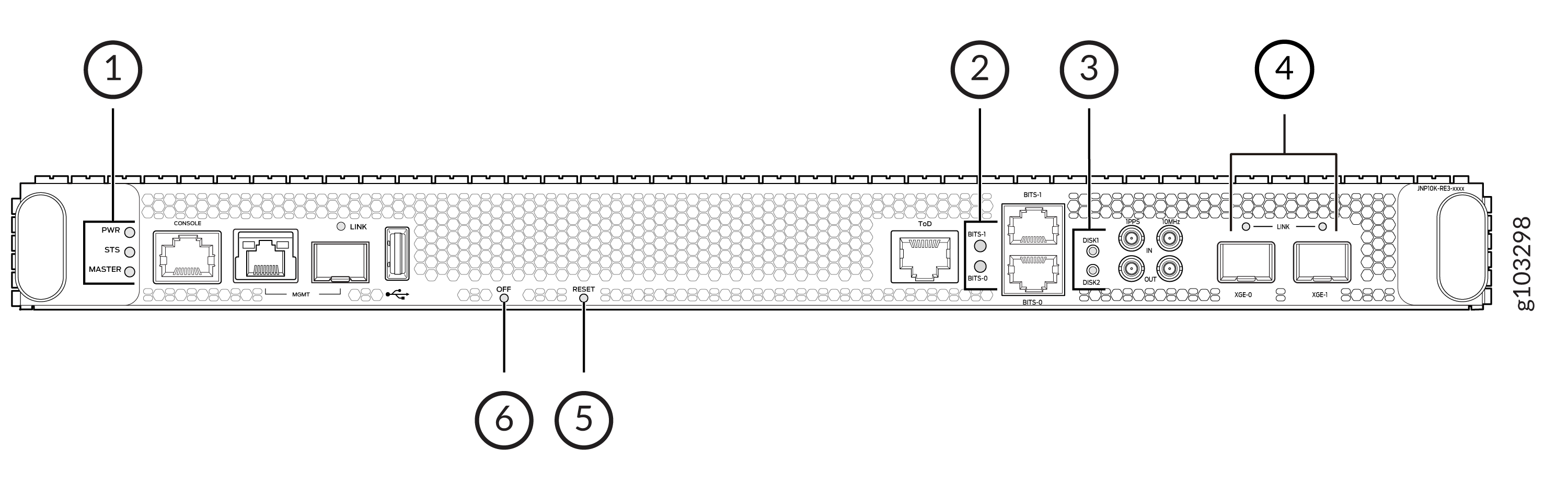
The MX10004-BASE configuration has a single RCB. The fully redundant configurations have two RCBs. The RCB also contains Precision Time Protocol (PTP) ports and four Media Access Control Security (MACsec) capable ports. See Figure 1.
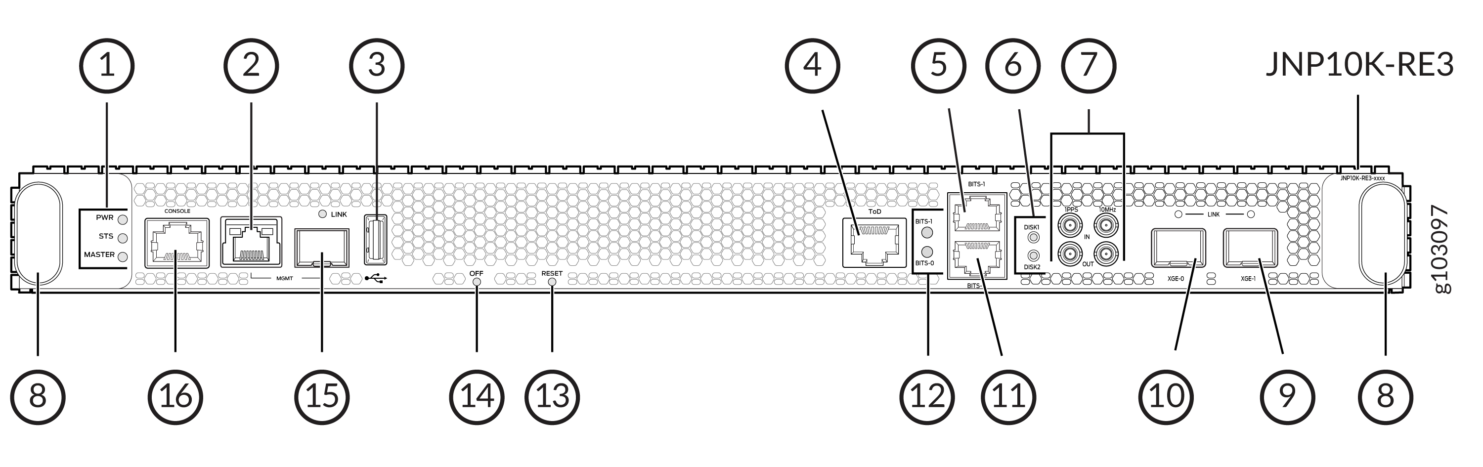
1 — RCB status LEDs | 9 — XGE-1 not used (reserved ports) |
2 — Management (MGMT) port | 10 — XGE-0 not used (reserved ports) |
3 — USB port | 11 — BITS0 clock port |
4 — ToD—Time-of-day (TOD) port | 12 — Clock LEDs |
5 — BITS1 clock port | 13 — Reset button |
6 — Solid State Disk (SSD) LEDs | 14 — Online/Offline button |
7 — GPS clock ports | 15 — Management (MGMT) port |
8 — Handles | 16 — Console (CONSOLE) port |
This topic covers:
Routing and Control Board Functions
The Routing and Control Board (RCB) integrates the control plane and Routing Engine functions into a single management unit. Each RCB provides all the functions needed to manage the operation of the modular chassis:
-
System control functions such as environmental monitoring
-
Routing Layer 2 and Layer 3 protocols
-
Communication to all components such as line cards, Switch Fabric Boards (SFBs), and power and cooling
-
Transparent clocking
-
Alarm and logging functions
Routing and Control Board Components
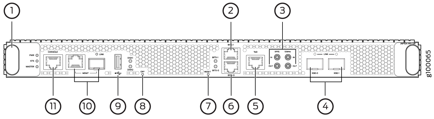
1 — Handles | 7 — Reset button |
2 — BITS1 clock port | 8 — Online/Offline button |
3 — GPS clock ports | 9 — USB port |
4 — XGE-0 and XGE-1 JCS ports | 10 — Management (MGMT) ports |
5 — ToD—Time-of-day (TOD) port | 11 — Console (CONSOLE) port |
6 — BITS0 clock port |
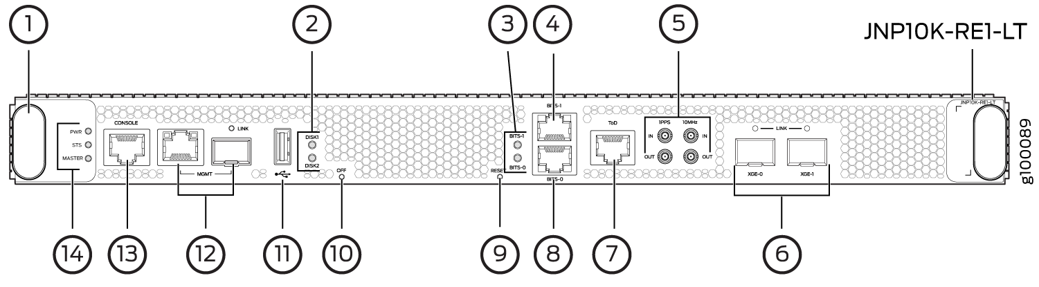
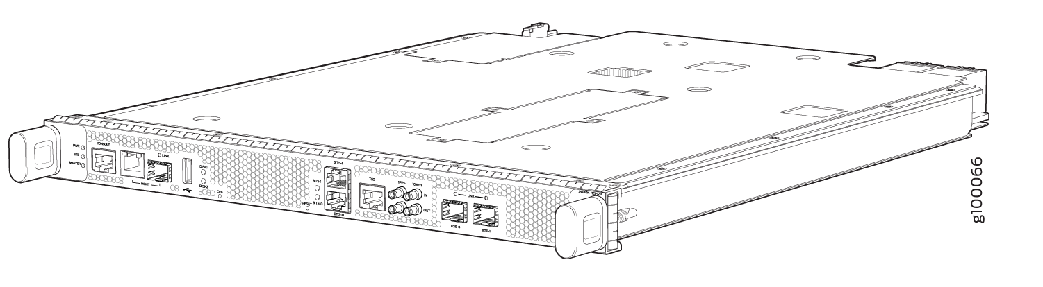
1 — Handles | 8 — BITS0 clock port |
2 — Solid State Disk (SSD) LEDs | 9 — Reset button |
3 — Clock LEDs | 10 — Online/Offline button |
4 — BITS1 clock port | 11 — USB port |
5 — GPS clock ports | 12 — Management (MGMT) ports |
6 — XGE-0 and XGE-1 JCS ports | 13 — Console (CONSOLE) port |
7 — ToD—Time-of-day (TOD) port | 14 — RCB status LEDs |
Each RCB consists of the following internal components:
-
CPU—Runs Junos OS to maintain the routing tables and routing protocols.
-
EEPROM—Stores the serial number of the Routing Engine.
-
DRAM—Provides storage for the routing and forwarding tables and for other Routing Engine processes.
-
One 10-Gigabit Ethernet interface between the Routing Engine and Switch Fabric Board.
-
One USB port—Provides a removable media interface through which you can install Junos OS manually. The Junos OS supports USB versions 3.0, 2.0, and 1.1.
-
Management ports—Two ports, one copper (RJ-45 port) and one SFP port provide access to management devices. Use only one of the two management ports at a time.
Use an RJ-45 connector for the copper port.
Use a fiber optic connector for the SFP port.
Do not use copper SFP or SFP-T modules in the SFP port because they are not supported.
-
RESET button—When pressed, reboots the RCB as detailed below:
-
When pressed for less than 5 seconds for diagnostic purposes, the RCB does not reset. The press event is logged in the RCB FPGA register.
-
When pressed for greater than 5 seconds but less than 10 seconds, the RCB reboots and the reset-reason logs the button press event.
-
When pressed for greater than 10 seconds, the RCB reboots with an option for BIOS recovery.
-
-
LEDs—Provide status of the Routing Engine.
-
Online/Offline Button—When the RCB is online and if the button is pressed for more than 4 seconds, the RCB goes offline. When the RCB is offline and if the button is pressed more than 4 seconds, the RCB starts booting.
For specific information about Routing Engine components (for
example, the amount of DRAM), issue the show vmhost
hardware command.
See Also
MX10008 Routing and Control Board LEDs
Figure 6 shows the LEDs on the Routing and Control Boards (JNP10K-RE1).
1 — RCB status panel LEDs | 4 — Link status LEDs for XGE-0 and XGE-1 ports |
2 — Clock LEDs–BITS-0, and BITS-1 | 5 — Reset button with LED |
3 — Solid State Disk (SSD) LEDs—DISK1 and DISK2 | 6 — On/Off button with LED |
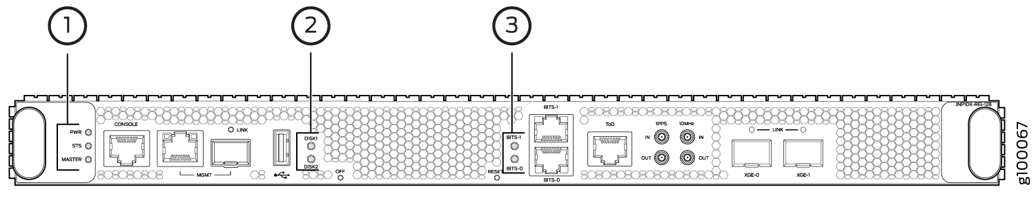
1 — Routing and Control Board status panel | 3 — Clock LEDs–BITS-0, and BITS-1 |
2 — Solid State Disk (SSD) LEDs—DISK1 and DISK2 |
Table 1 describes the LEDs on the RCB status panel.
|
LED |
Color |
State |
Description |
|---|---|---|---|
|
PWR |
Green |
On steadily |
RCB is receiving adequate power. |
|
Amber |
Blinking |
An error has been detected in the RCB. |
|
|
Dark |
Unlit |
RCB is not powered up. |
|
|
STS |
Green |
On steadily |
RCB is online and functioning correctly. |
|
Green |
Blinking |
The beacon feature is enabled. |
|
|
Amber |
On steadily |
The RCB is booting. |
|
|
Amber |
Blinking |
An error has been detected in the RCB. |
|
|
Dark |
Unlit |
The power supply is switched off. |
|
|
MST |
Green |
On steadily |
The RCB is the primary. |
|
Dark |
Unlit |
The RCB is the backup. |
Figure 7 shows the management port LEDs on the RCB.
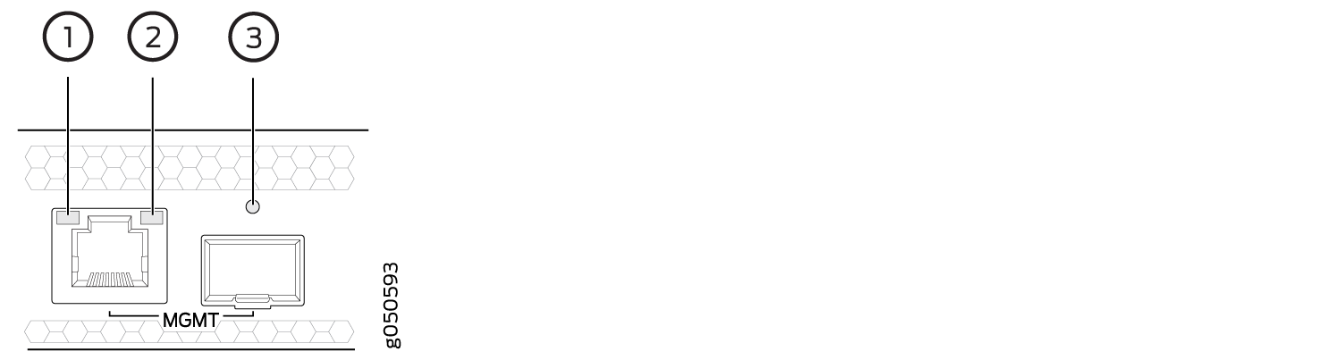
1 — Status LED (RJ-45) | 3 — Link LED—Green indicates the link is up; blinking indicates activity (SFP) |
2 — Activity LED (RJ-45) |
Table 2 describes the RJ-45 management port and SFP LEDs.
|
LED |
Color |
State |
Description |
|---|---|---|---|
|
Activity/Status LED |
Unlit |
Off |
The port speed is 10 MB. |
|
Green |
Blinking |
The port speed is 100 MB. |
|
|
Green |
On steadily |
The port speed is 1000 MB. |
|
|
LINK |
Unlit |
Off |
No link is established, there is a fault, or the link is down. |
|
Green |
On steadily |
A link is established. |
|
|
Blinking |
There is link activity. |
||
|
Amber |
Blinking or flickering |
The beacon feature is enabled. |
Table 3 describes the JCS Port LEDs.
|
LED |
Color |
State |
Description |
|---|---|---|---|
|
LINK LEDs for JCS Ports (XGE0 and XGE1) |
Unlit |
Off |
No transceiver is present. |
|
Green |
On steadily |
A link is established. The interface is up. |
|
|
Green |
Blinking or flickering |
The beacon feature is enabled. |
|
|
Amber |
Blinking |
An error has occurred. |
Table 4 describes the LEDs for the secondary SATA drives.
|
LED |
Color |
State |
Description |
|---|---|---|---|
|
DISK1 and DISK2 |
Green |
On steadily |
A SATA drive is present. |
|
Green |
Blinking |
The drive is active. |
|
|
Amber |
On steadily |
The drive is active. |
|
|
Dark |
Unlit |
A drive is not installed. |
|
LEDs |
Color/State |
Description |
|---|---|---|
|
Clock LEDs—BITS-0 and BITS-1 |
Green |
The clock synchronization source is configured and qualified, the clock synchronization output is configured, and the output is active. |
|
The clock synchronization source is not configured but the clock synchronization output is configured and active. |
||
|
The clock synchronization source is configured and qualified but the clock synchronization output is not configured. |
||
|
Red |
The clock synchronization source is configured and qualified, and the output is active and is in holdover state. |
|
|
The clock synchronization source is not configured, but the output is active and is in holdover state. |
||
|
The clock synchronization source is configured, but has failed. |
||
|
The TX status is in squelch mode. |
||
|
Off |
Both the clock synchronization source and the clock synchronization output are not configured. |
|
LEDs |
Color |
State |
Description |
|---|---|---|---|
|
Clock LEDs—BITS-0 and BITS-1 |
Red |
Off |
Clock is active. |
|
On steadily |
Clock is not working. |