Removing and Installing MX10008 Switch Fabric Boards
Handling and Storing MX10008 Switch Fabric Boards
The MX10008 Switch Fabric Boards (SFBs have fragile components. To avoid damaging the SFBs, you must follow safe handling practices.
Holding Switch Fabric Boards
While removing an SFB from the router chassis, you should hold the SFB vertically until it is clear of the router chassis. Then you should rotate the SFB 90 degrees and place it on an antistatic mat or in an electrostatic bag for storage (see Figure 1).
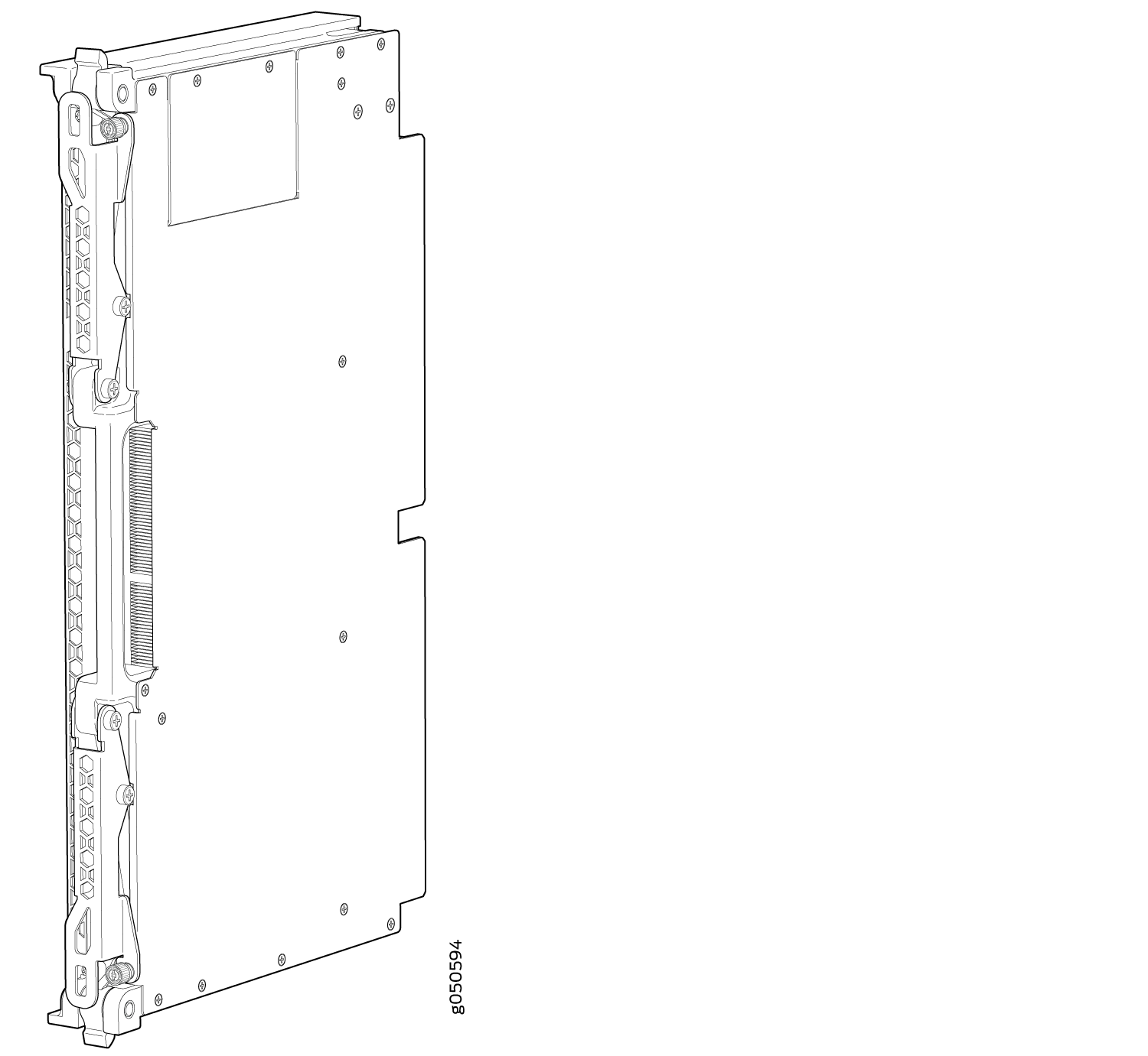
The proper method of holding an SFB is to:
Storing Switch Fabric Boards
You must store SFBs either in the chassis or in a spare shipping container, horizontally and sheet-metal side down. Do not stack these units on top of one another or on top of any other component. Place each unit separately in an antistatic bag or on an antistatic mat placed on a flat, stable surface.
Because these units are heavy, and because antistatic bags are fragile, inserting the line card into the bag is best done by two people.
The JNP10008-SF2 SFBs are shipped with protective plastic covers on the fabric interface connectors. The plastic covers keep the connectors clean and free of dust and other particles. When you remove JNP10008-SF2 SFB from the router, re-insert the protective plastic covers on the fabric interface connectors and then place the SFB in an antistatic bag or on an antistatic mat placed on a flat, stable surface.
To insert an SFB into an electrostatic bag:
- Hold the unit horizontally with the faceplate toward you.
- Have the second person slide the opening of the antistatic bag over the connector edge and then pull the bag to cover the unit.
If you must insert an SFB into a bag by yourself:
Lay the unit horizontally on an antistatic mat that is on a flat, stable surface with the sheet metal side down.
Orient the unit with the faceplate toward you.
Carefully insert the connector edge into the opening of the bag and pull the bag toward you to cover the unit.
Removing an MX10008 Switch Fabric Board
An MX10008 router has six Switch Fabric Boards (SFBs) that are located in the middle of the chassis behind the fan trays. SIB 0 through SIB 2 are located behind the left fan tray and SIB 3 through SIB 5 are located behind the right fan tray. You must remove the appropriate fan tray to access the failing SFB. See Removing an MX10008 Fan Tray.
Ensure you have the following equipment on hand before replacing an SFB:
-
Electrostatic bag or antistatic mat
-
Electrostatic discharge (ESD) grounding strap
-
Replacement SFB
-
SFB blank (JNP10008-SF-BLNK)
Do not remove the SFB unless you have a replacement SFB or a SFB blank (JNP10008-SF-BLNK) available.
If you are not installing another SFB into the empty card slot within a short time, install the SFB blank into the slot to maintain proper airflow in the card cage.
To remove an SFB (see Figure 4):
-
Wrap and fasten one end of an ESD strap around your bare wrist, and connect the
other end of the strap to the ESD point on the chassis. There is an ESD point
located next to the protective earthing terminal and below
PSU 5 on the MX10008 rear panel (see Figure 2).
Figure 2: ESD Point on MX10008 Chassis Rear
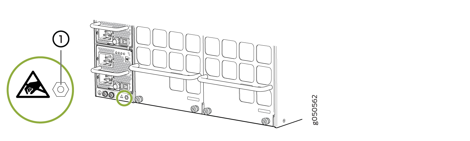 1—
1—ESD point
-
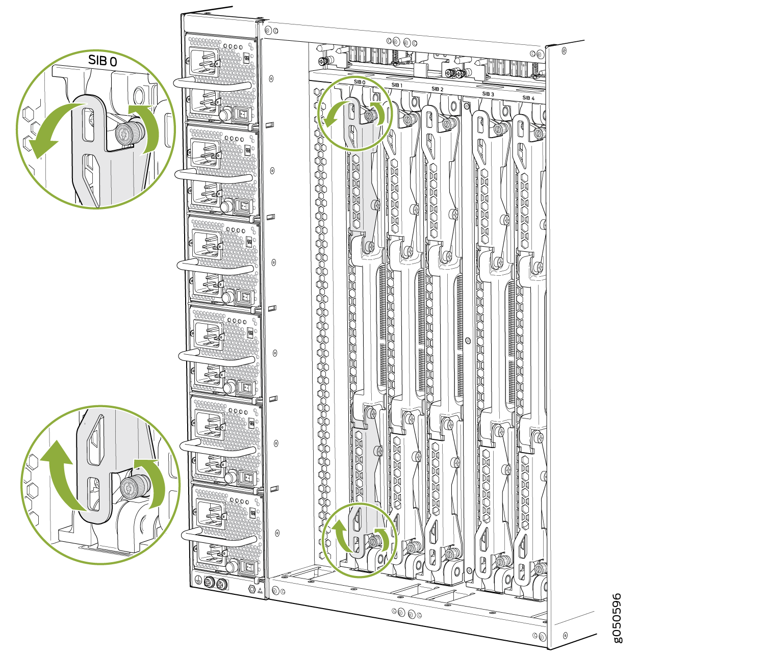
Grasp both handles and spread them apart, and then slide the SFB about a
quarter of the way out of the slot. See Figure 3.
Figure 3: Loosening Captive Screws and Spread Ejector Handles
-
Grasp the ejector handle with one hand and place your other hand under the SFB
for support as you slide the SFB out of the slot (see Figure 4).
CAUTION:
The SFB surface and handles may be hot. Allow a few minutes for the surface and handles to cool by pulling out the SFB halfway out of the chassis. Wear proper protective, heat-resistant gloves while removing an SFB.
Figure 4: Removing the SFB from an MX10008 Chassis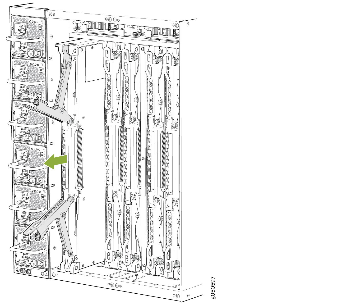
-
Support the SFB as you rotate the SFB 90 degrees and place it on the antistatic
mat with the printed circuit board facing upward. Be careful not to bump or
handle the SFB by the connectors. If you do not have an antistatic mat, have
another person help you slide the electrostatic bag over the SFB before placing
it on the stable surface. See Figure 5.
CAUTION:
Do not stack hardware components on top of one another after you remove them. Place each component on an antistatic mat resting on a stable, flat surface.
Figure 5: Extracted SFB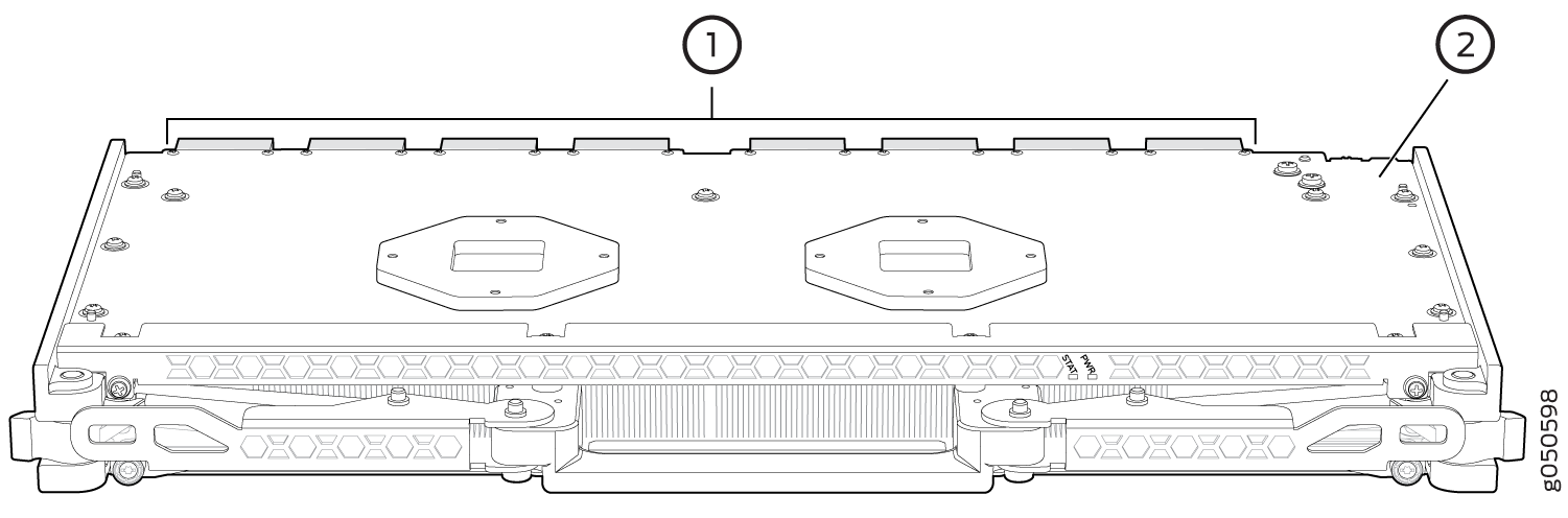 1—
1—Connectors
2—Printed circuit board
-
If you removed an JNP10008-SF2 SFB from the router, re-insert the protective
plastic covers on the fabric interface connectors of the SFB to keep the
connectors clean and free of dust and other particles (see Figure 6).
Figure 6: Inserting Protective Plastic Covers on JNP10008-SF2 SFB Interface Connectors
Installing an MX10008 Switch Fabric Board
An MX10008 router has six Switch Fabric Boards (SFBs) that are located in the middle of the chassis behind the fan trays. SFB 0 through SFB 2 are located behind the left fan tray, and SFB 3 through SFB 5 are located behind the right fan tray. You must remove the appropriate fan tray to install an SFB. See Removing an MX10008 Fan Tray. Fan trays must be replaced within the duration mentioned in Table 1.
Chassis Ambient Temperature |
Duration |
|---|---|
27°C |
5 minutes |
35°C |
3 minutes |
40°C |
2 minutes |
When replacing the fans or SIBs at 40°C chassis ambient temperature, ensure that the fans run at 100% fan speed for at least 10 minutes before replacing the fans or SIBs.
Use the test chassis fan tray 0 speed full-speed and test chassis fan tray 1 speed full-speed commands to set the chassis fans to 100% speed.
Ensure you have the following equipment on hand before installing an SFB:
Electrostatic bag or antistatic mat
Electrostatic discharge (ESD) grounding strap
Replacement SFB
To install an SFB:
- Wrap and fasten one end of an ESD strap around your bare
wrist, and connect the other end of the strap to the ESD point on
the chassis. There is an ESD point located next to the protective
earthing terminal and below PSU 5 on the
MX10008 rear panel (see Figure 7).Figure 7: ESD Point on MX10008 Chassis Rear1—
ESD point
-
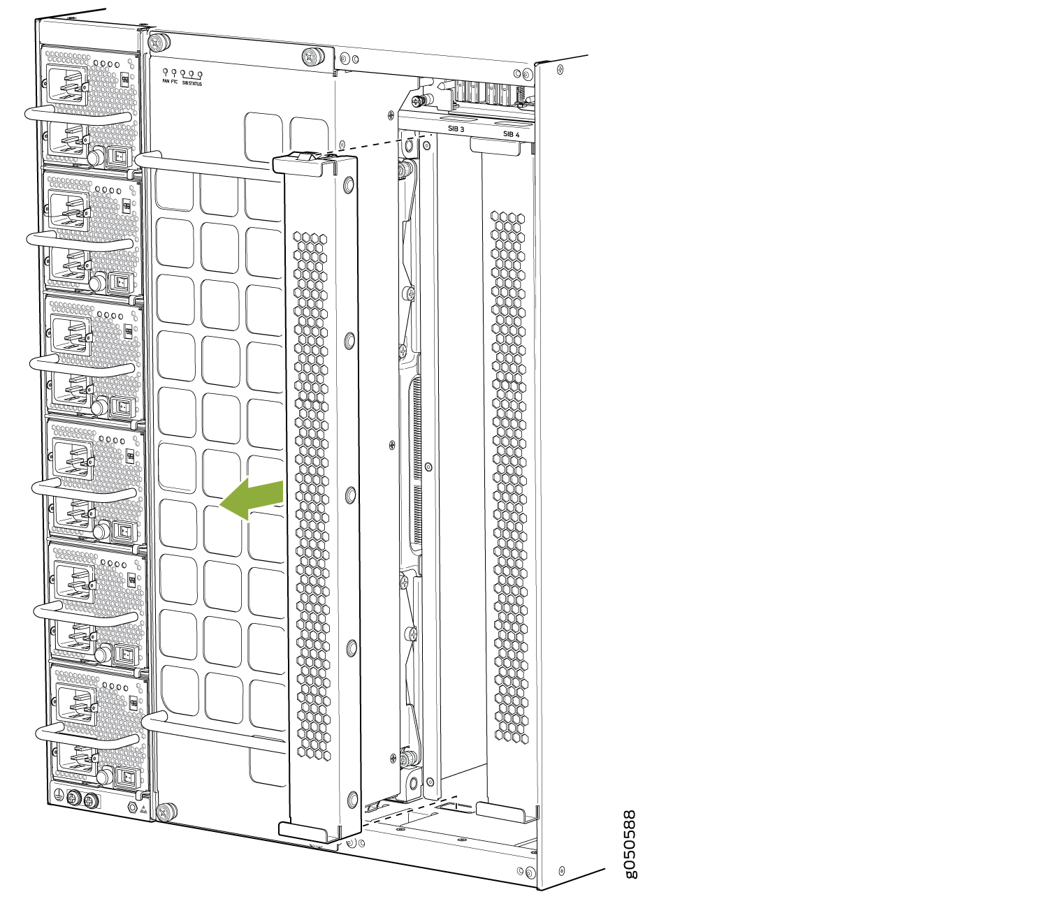
Either remove the failing SFB and store it in an electrostatic bag or on an
antistatic mat (see Removing an MX10008 Switch Fabric Board) or remove the cover panel by grasping each side of the plate and pulling the
panel straight out (see Figure 8 for an example using the MX10008).
Figure 8: Removing an SFB Cover Plate on an MX10008
-
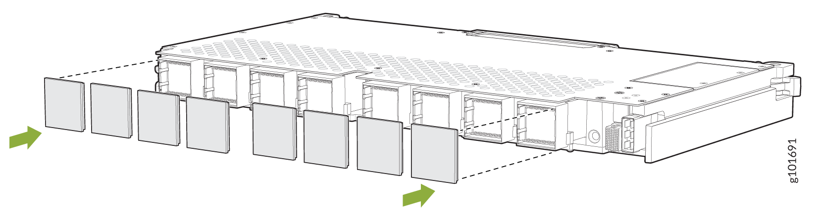
If you are installing JNP10008-SF2 SFBs, remove the protective plastic covers
on the fabric interface connectors and save the plastic covers for future use
(see Figure 9).
Figure 9: Removing Protective Plastic Covers from JNP10008-SF2 SFB Interface Connectors
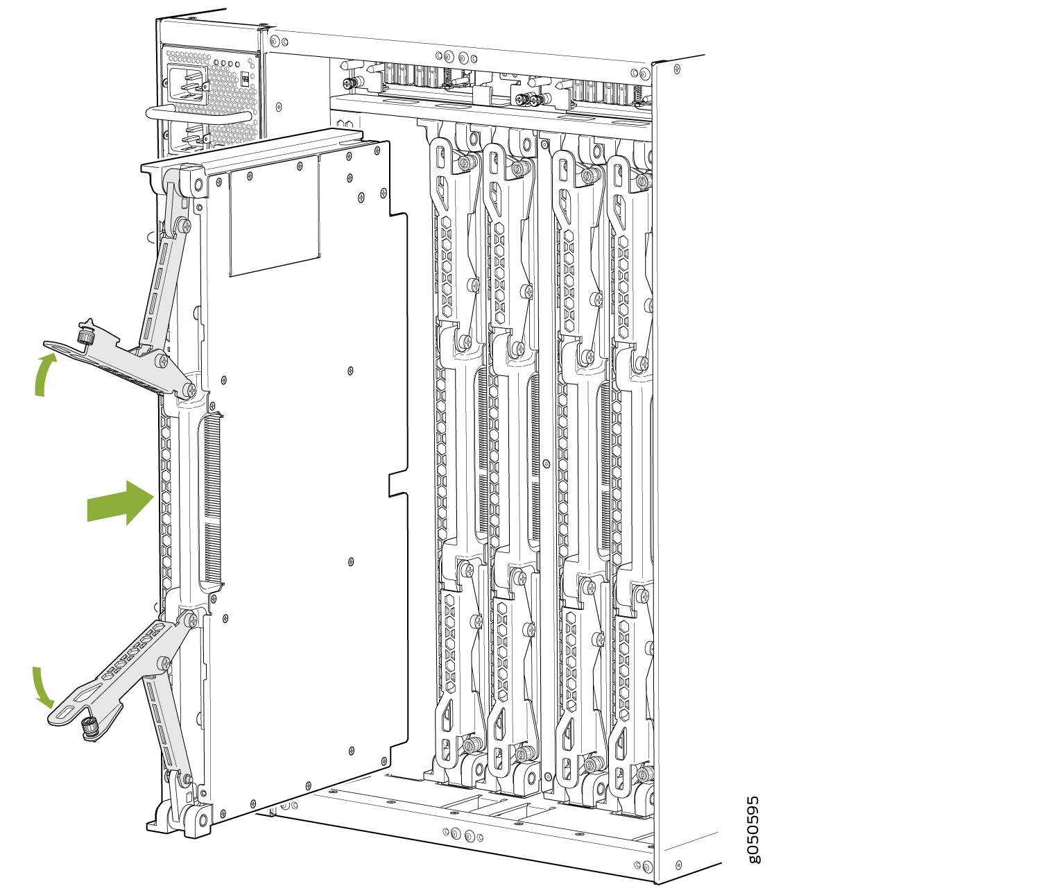
- Grasp the two ejector handles and fold them inward until
they latch to so that the SFB is fully seated (see Figure 10 for the MX10008.Figure 10: Installing an MX10008 SFB
Upgrade from JNP10008-SF to JNP10008-SF2
The MX10008 routers support Switch Fabric Board (SFB; model number: JNP10008-SF) and the enhanced Switch Fabric Board (SFB2; model number: JNP10008-SF2). SFB2 is designed to support higher bandwidth than that provided by SFB on the MX10008 routers.
This topic explains how to upgrade from JNP10008-SF Switch Fabric Board (SFB) to enhanced Switch Fabric Board JNP10008-SF2 on MX10008 routers.
Smooth upgrade from JNP10008-SF to JNP10008-SF2 is not supported in MX10008 routers.
The MX10008 routers support either JNP10008-SF or JNP10008-SF2 only. The routers do not support JNP10008-SF and JNP10008-SF2 at the same time.
The JNP10008-SF2 operates only with the following power supplies and fan tray:
-
JNP10K-PWR-AC2 power supply
-
JNP10K-PWR-AC3 power supply
-
JNP10K-PWR-DC2 power supply
-
JNP10K-PWR-DC3 power supply
-
JNP10K-PWR-AC3H power supply
-
JNP10008-FAN2 fan tray
-
JNP10008-FAN3 fan tray
-
JNP10008-FTC2 fan tray controller
-
JNP10008-FTC3 fan tray controller
Ensure that you have the following tools and parts before upgrading from SFB to SFB2:
-
Electrostatic bag or antistatic mat
-
Electrostatic discharge (ESD) grounding strap
-
Phillips screwdriver, number 2
-
JNP10008-SF2s
-
JNP10008-FAN2 or JNP10008-FAN3 fan trays and JNP10008-FTC2 or JNP10008-FTC3 fan tray controllers if your MX10008 router has JNP10008-FAN trays and JNP10008-FAN-CTLR installed
-
JNP10K-PWR-AC2,JNP10K-PWR-AC3, JNP10K-PWR-DC2, or JNP10K-PWR-AC3H power supplies if your MX10008 router has JNP10K-PWR-AC or JNP10K-PWR-DC power supplies installed
Ensure that you complete the following tasks before upgrading from JNP10008-SF to JNP10008-SF2:
-
Prepare the router and install the version of Junos OS Release (21.4R1 or later) that supports SFB2.
-
Use the following CLI command to power off both the Routing and Control Boards (RCBs).
user@host>request vmhost power-off
-
Wait for the RCBs to gracefully shut down. Once the RCBs are powered off the router will automatically shut down.
Remove JNP10008-SFs
-
Wrap and fasten one end of an ESD strap around your bare wrist, and connect the other end of the strap to the ESD point on the chassis.
-
Remove both the fan trays. See Removing and Installing MX10008 Cooling System Components.
-
Using your fingers, loosen the captive screws at the top and bottom of the SFB.
-
Grasp both handles and spread them apart, and then slide the SFB about a quarter of the way out of the slot.
-
Grasp the ejector handle with one hand and place your other hand under the SFB for support as you slide the SFB out of the slot see (Figure 11).
CAUTION:The SFB surface and handles may be hot. Allow a few minutes for the surface and handles to cool by pulling out the SFB halfway out of the chassis. Wear proper protective, heat-resistant gloves while removing an SFB.
Figure 11: Removing the SFB from an MX10008
-
Support the SFB as you rotate the SFB 90 degrees and place it on the antistatic mat with the printed circuit board facing upward. Be careful not to bump or handle the SFB by the connectors. If you do not have an antistatic mat, have another person help you slide the electrostatic bag over the SFB before placing it on the stable surface.
CAUTION:Do not stack hardware components on top of one another after you remove them. Place each component on an antistatic mat resting on a stable, flat surface.
-
Repeat step 3 to step 6 to remove the remaining SFBs.
-
Remove the power supplies if you have JNP10K-PWR-AC or JNP10K-PWR-DC power supplies installed on your router. See Removing and Installing MX10000 Power System Components
-
Place all the removed SFBs, power supplies, and fan trays in Electrostatic bags or on antistatic mat.
Install JNP10008-SF2s
-
Wrap and fasten one end of an ESD strap around your bare wrist, and connect the other end of the strap to the ESD point on the chassis.
-
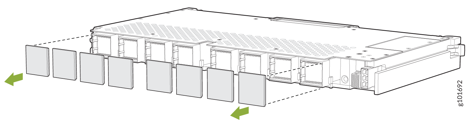
Remove the protective plastic covers that are on the fabric interface connectors of the JNP10008-SF2 SFB and save them for future use (see Figure 12).
Figure 12: Removing Protective Plastic Covers from JNP10008-SF2 SFB Interface Connectors
-
Lift the JNP10008-SF2 by the handle with one hand and support the lower edge with the other hand.
-
Holding the JNP10008-SF2 vertically, slide the JNP10008-SF2 into the open slot until the ejector handles engage and start to close.
-
Grasp the two ejector handles and fold them inward until they latch to seat the JNP10008-SF2 (see Figure 13).
Figure 13: Installing an JNP10008-SF2
-
Hand-tighten the captive screws.
-
Repeat step 2 to step 5 to install the remaining JNP10008-SF2s.
-
Install the JNP10008-FAN2 or JNP10008-FAN3 fan trays and JNP10008-FTC2 or JNP10008-FTC3 fan tray controllers. See Removing and Installing MX10008 Cooling System Components.
-
Install the JNP10K-PWR-AC2/JNP10K-PWR-AC3 or JNP10K-PWR-DC2/JNP10K-PWR-DC3 power supplies if you removed the JNP10K-PWR-AC or JNP10K-PWR-DC power supplies from the router.
-
Power on the router.