Removing and Installing MX10008 Cooling System Components
An MX10008 router has two independent, field-replaceable fan trays. Fan trays must be replaced within the duration mentioned in Table 1.
Chassis Ambient Temperature |
Duration |
|---|---|
27°C |
5 minutes |
35°C |
3 minutes |
40°C |
2 minutes |
When replacing the fans or SFBs at 40°C chassis ambient temperature, ensure that the fans run at 100% fan speed for at least 10 minutes before replacing the fans or SFBs.
Use the test chassis fan tray 0 speed full-speed and
test chassis fan tray 1 speed full-speed
commands to set the chassis fans to 100% speed.
To install or remove the fan trays and fan tray controller, see the following sections:
Removing an MX10008 Fan Tray
Before you remove a fan tray:
-
Ensure you understand how to prevent ESD damage. See Prevention of Electrostatic Discharge Damage.
-
Ensure that you have the following parts and tools available to remove a fan tray:
-
Electrostatic discharge (ESD) grounding strap
-
Replacement fan tray
-
A Phillips (+) screwdriver, number 1 or 2 (optional), for the captive screws
-
An MX10008 has two independent, field-replaceable fan trays. Each fan tray is a hot-removable and hot-insertable field-replaceable unit (FRU); you can remove and replace the fan tray while the router is running without turning off power to the router or disrupting routing functions. There are three models of the fan tray, JNP10008-FAN, JNP10008-FAN2, and JNP10008-FAN3.
Do not remove the fan tray unless you have a replacement fan tray available.
Each fan tray is installed vertically on the rear, or FRU-side, of the chassis.
A fan tray can be removed and replaced while the router is operating. Fan trays must be replaced within the duration mentioned in Table 1.
To remove either the JNP10008-FAN, JNP10008-FAN2, or JNP10008-FAN3 fan tray:
-
Attach the electrostatic discharge (ESD) grounding strap
to your bare wrist, and connect the strap to the ESD point on the
rear left side of the chassis. See Figure 1.
Figure 1: ESD Point on the Rear of an MX10008
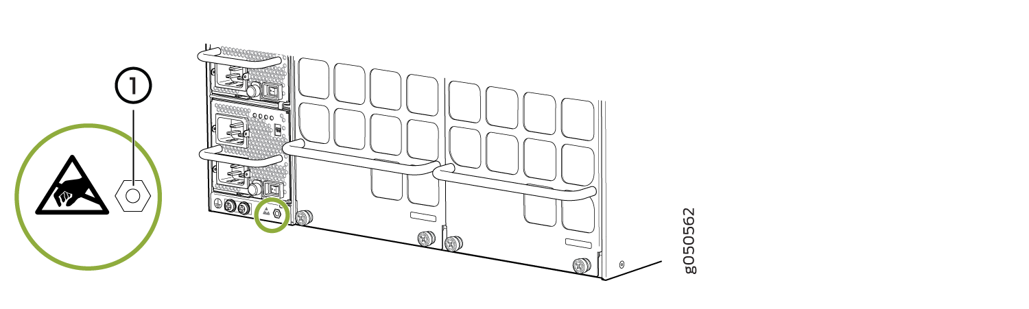 1—
1—ESD point
-
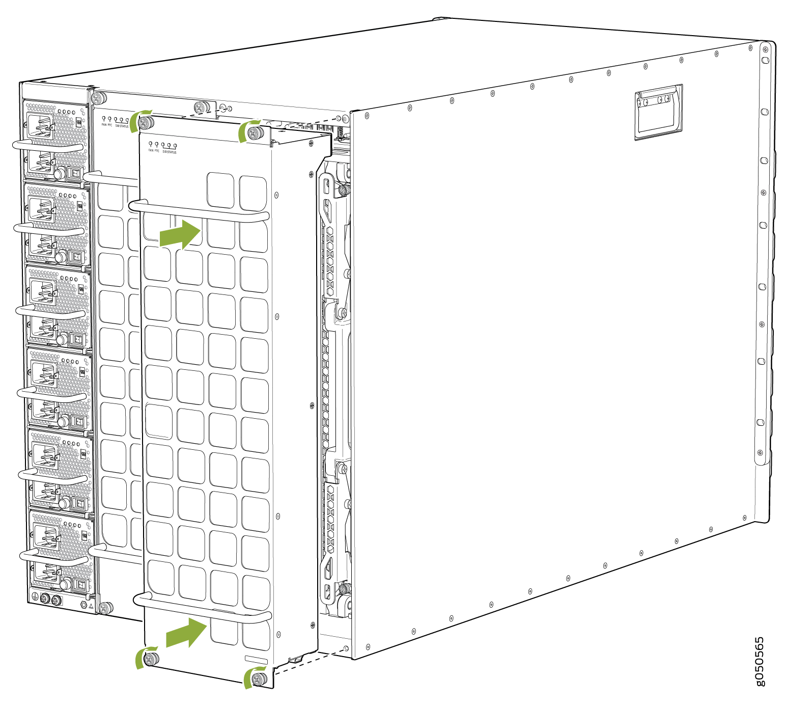
Grasp the top and bottom handles and pull the fan tray out about 3 in. (7.6 cm). See
Figure 2,
Figure 3, or Figure 4.
Figure 2: Removing Fan Tray JNP10008-FAN from an MX10008
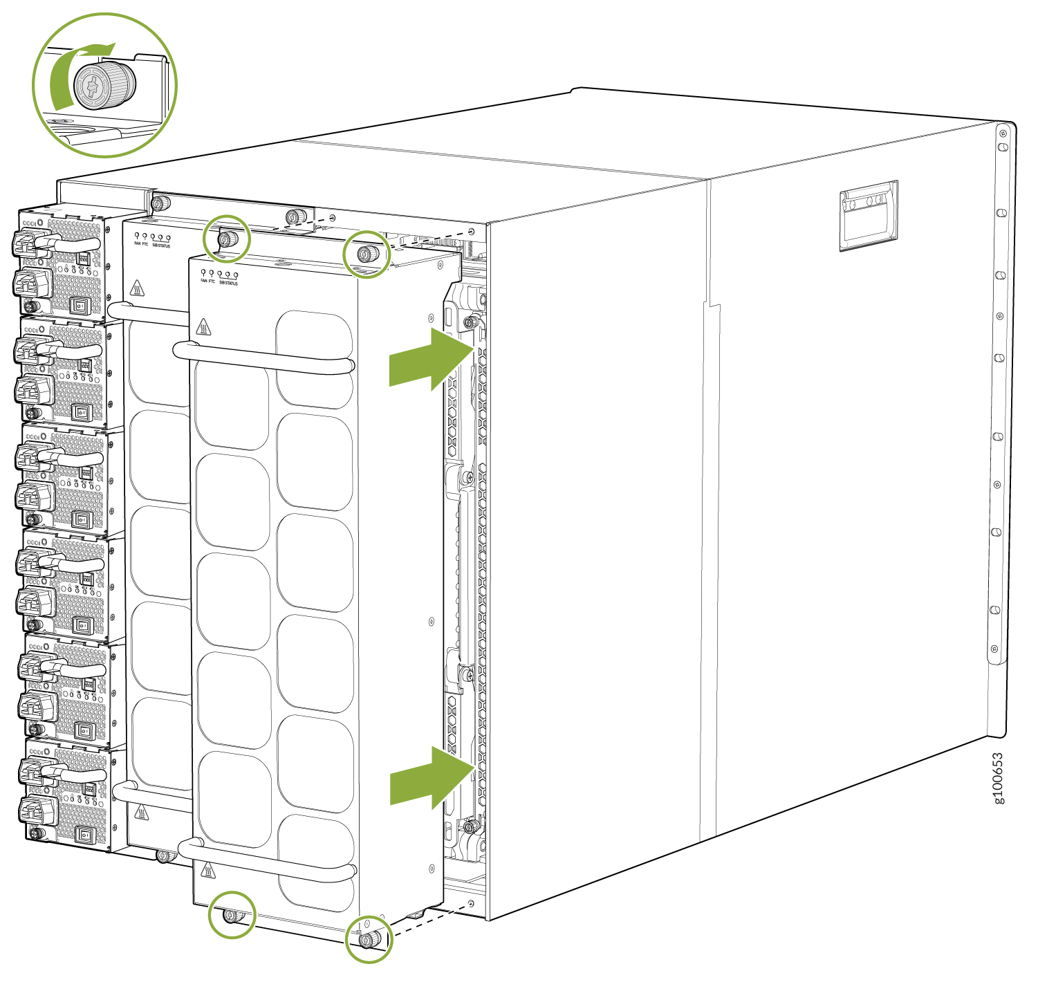
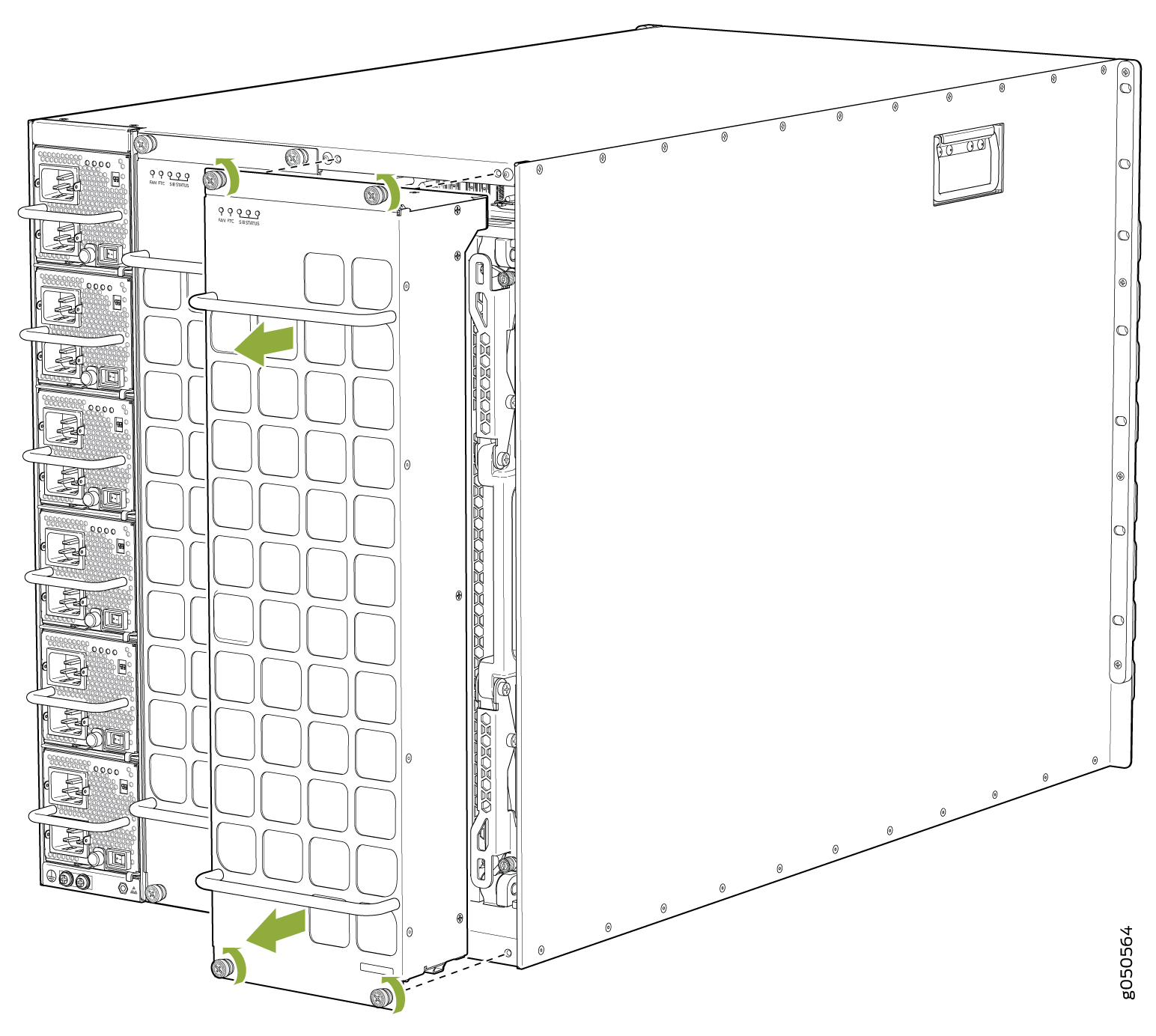 Figure 3: Removing Fan Tray JNP10008-FAN2 from an MX10008
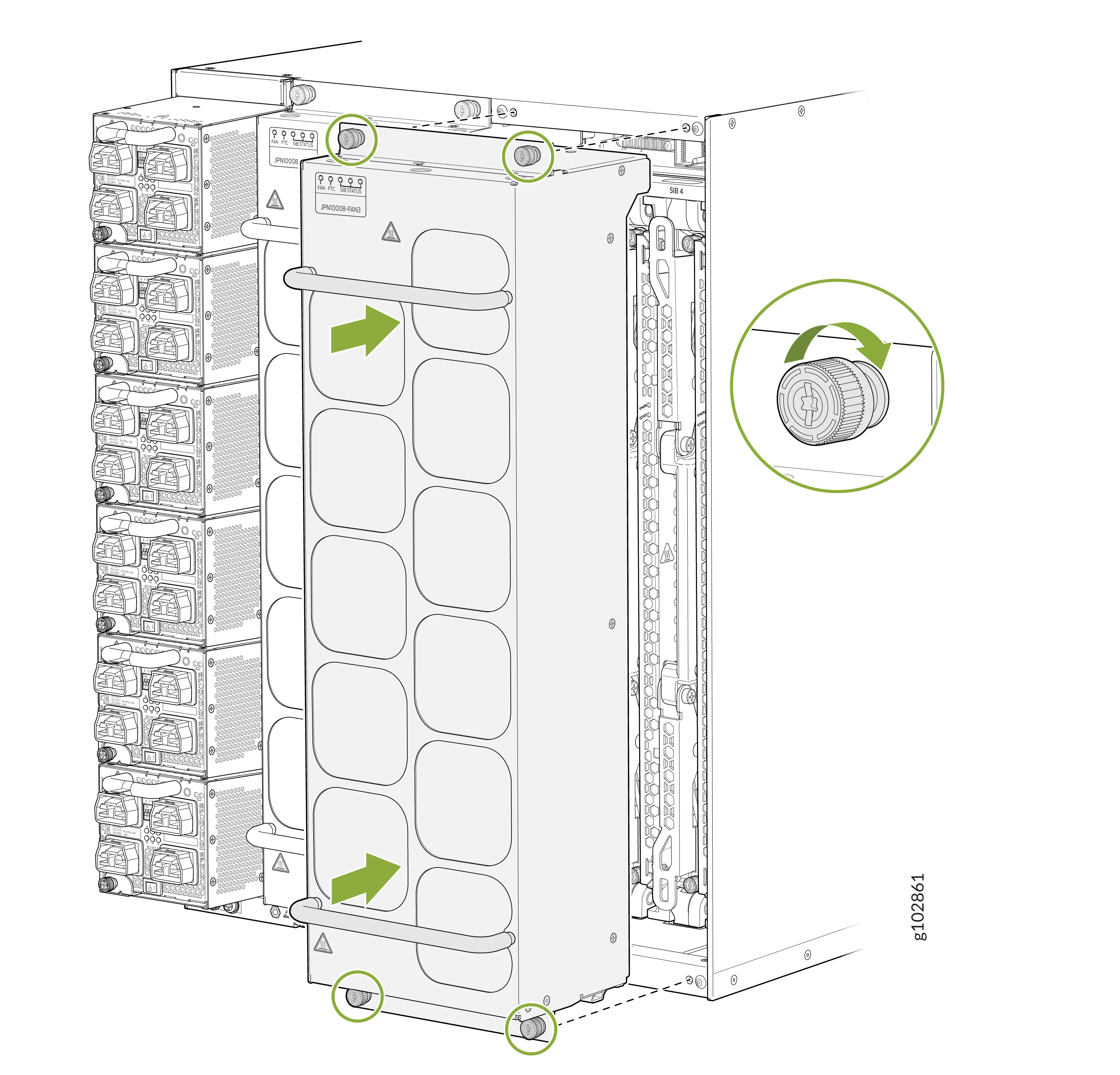
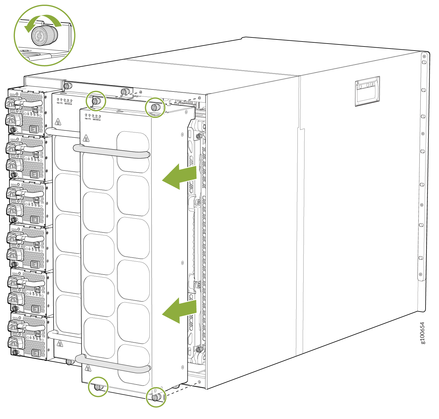 Figure 4: Remove a JNP10008-FAN3 Fan Tray from an MX10008
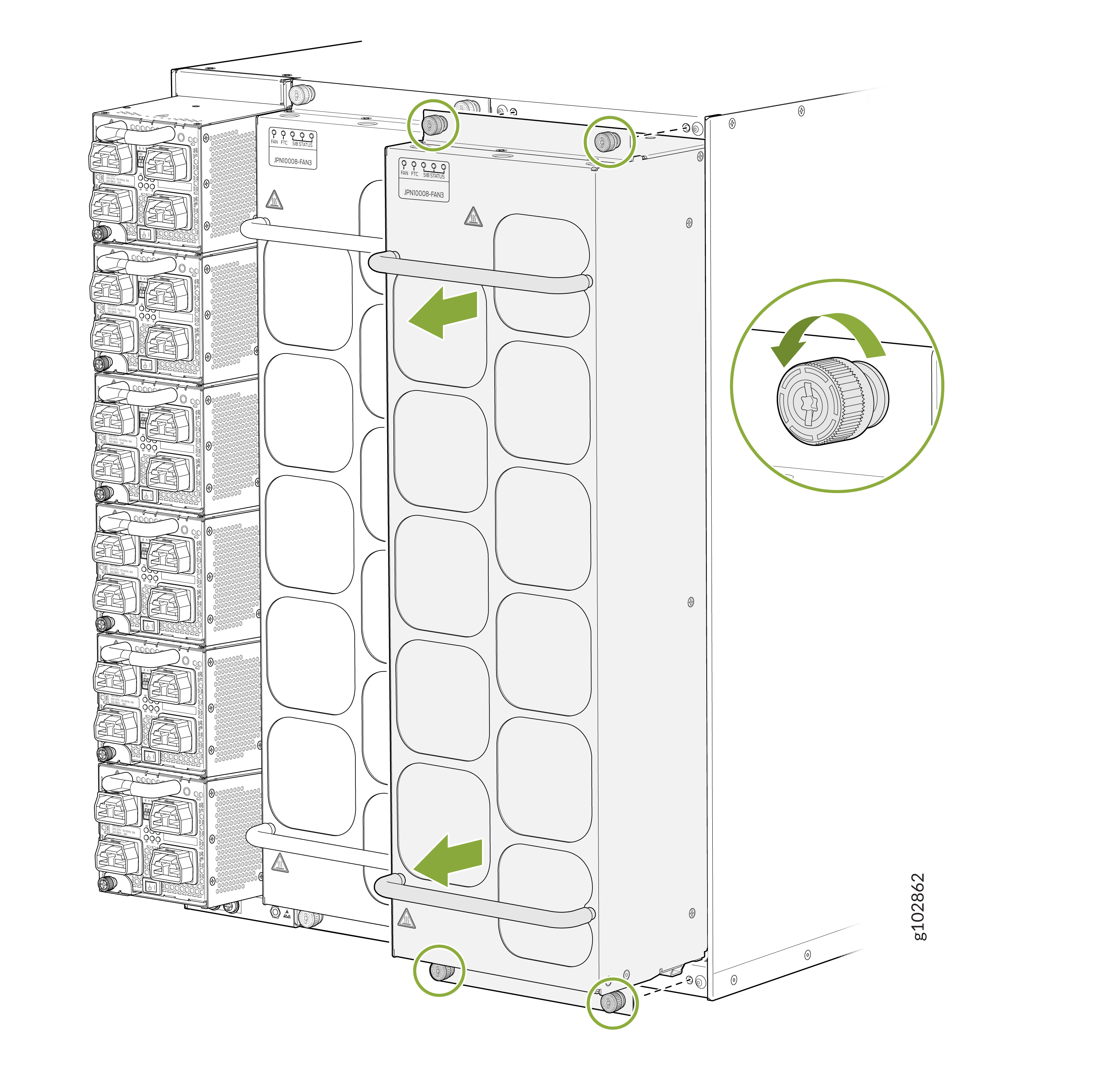
-
Tilt the top of the fan tray forward.
CAUTION:
See the heat symbol
 on the fan tray. The fan handle and its surfaces including the power
supply handles may be hot. Wear proper protective, heat-resistant
gloves while removing the fan tray.
on the fan tray. The fan handle and its surfaces including the power
supply handles may be hot. Wear proper protective, heat-resistant
gloves while removing the fan tray.
See Also
Installing an MX10008 Fan Tray
Before you begin to install a fan tray:
Ensure you understand how to prevent ESD damage. See Prevention of Electrostatic Discharge Damage.
Ensure that you have the following parts and tools available to install a fan tray:
Electrostatic discharge (ESD) grounding strap
A Phillips (+) screwdriver, number 1 or 2 (optional), for the captive screws
A replacement fan tray
The fan tray can be removed and replaced while the router is operating. Fan trays must be replaced within the duration mentioned in Table 1.
An MX10008 chassis has two independent, field-replaceable fan trays. Each fan tray is a hot-removable and hot-insertable field-replaceable unit (FRU); you can remove and replace the fan tray while the router is running without turning off power to the router or disrupting routing functions. There are three models of the fan tray, JNP10008-FAN, JNP10008-FAN2, and JNP10008-FAN3.
Each fan tray is installed vertically on the rear, or FRU-side, of the chassis.
To install either the JNP10008-FAN, JNP10008-FAN2, or the JNP10008-FAN3 fan tray:
- Attach the ESD grounding strap to your bare wrist, and
connect the strap to the ESD point on the rear left side of the chassis
(see Figure 5).Figure 5: ESD Point on the Rear of an MX100081—
ESD point
See Also
Removing an MX10008 Fan Tray Controller
For each of the two fan trays, there is a fan tray controller. Each controller is a hot-removable and hot-insertable field-replaceable unit (FRU); you can remove and replace one fan tray controller while the router is running without turning off power to the router or disrupting routing functions. There are three models of fan tray controller for the MX10008:
-
JNP10008-FAN-CTRL, which supports fan tray JNP10008-FAN
-
JNP10008-FTC2, which supports fan tray JNP10008-FAN2
-
JNP10008-FTC3, which supports fan trays JNP10008-FAN3 and JNP10008-FAN2
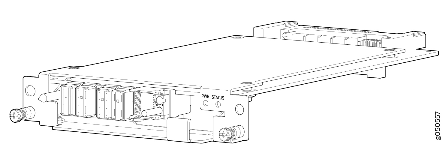
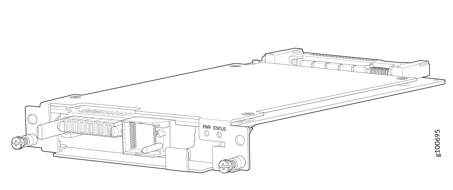
See Figure 9 for JNP10008-FAN-CTRL and Figure 10.
Do not remove the fan tray controller unless you have a replacement controller available.
To access a fan tray controller, you must first remove the fan tray. With the fan tray removed, the fan tray controller is installed horizontally above the Switch Fabric Boards (SFBs) at the top of the chassis.
Before you remove a fan tray controller:
Ensure you understand how to prevent ESD damage. See Prevention of Electrostatic Discharge Damage.
Ensure that you have the following parts and tools available to remove a fan tray controller:
Electrostatic discharge (ESD) grounding strap
An electrostatic bag or an antistatic mat
Replacement fan tray controller
A Phillips (+) screwdriver, number 1, for the captive screws
All models of fan controller are removed using the same procedure.
-
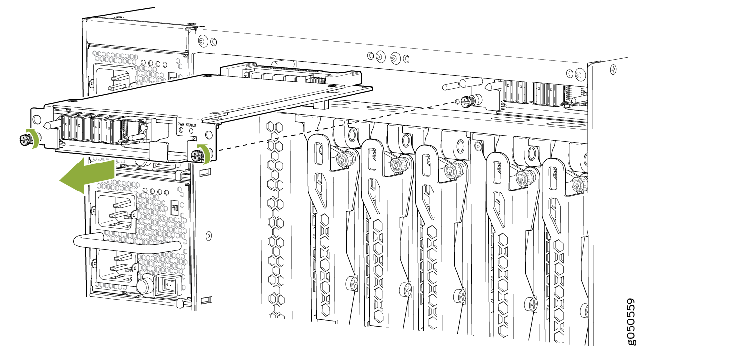
Grasp the fan tray controller and pull it straight out of the slot. See Removing an MX10008 Fan Tray Controller for the MX10008.
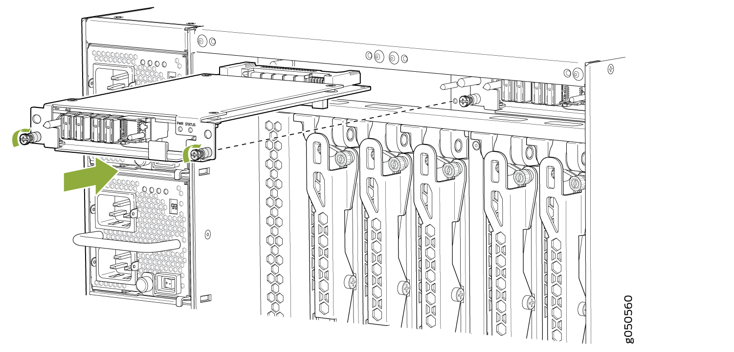
Figure 11: Removing an MX10008 Fan Tray Controller
Installing an MX10008 Fan Tray Controller
Each fan tray of an MX10008, has a fan tray controller. Each controller is a hot-removable and hot-insertable field-replaceable unit (FRU); you can remove and replace one fan tray controller while the router is running without turning off power to the router or disrupting routing functions. There are two models of fan tray controller for the MX10008, JNP10008-FAN-CTRL and JNP10008-FTC2, see Figure 12 and Figure 13.
Do not remove the fan tray controller unless you have a replacement controller available.
To access a fan tray controller, you must first remove the associated fan tray. With the fan tray removed, the fan tray controller is installed horizontally above the Switch Fabric Boards (SFBs) at the top of the chassis.
Before you replace a fan tray controller:
Ensure you understand how to prevent ESD damage. See Prevention of Electrostatic Discharge Damage.
You have removed the associated fan tray and fan tray controller. See Removing an MX10008 Fan Tray and Removing an MX10008 Fan Tray Controller.
Ensure that you have the following parts and tools available to install a fan tray controller:
Electrostatic discharge (ESD) grounding strap
Replacement fan tray controller
A Phillips (+) screwdriver, number 1 for the captive screws
To install a fan tray controller:
- Carefully slide the fan tray controller into the fan tray
controller slot until it is flush with the mounting holes. See Figure 14.Figure 14: Replacing an MX10008 Fan Tray Controller