Help us improve your experience.

Let us know what you think.

Do you have time for a two-minute survey?


Collapsed Spine Fabric Design and Implementation

In collapsed spine fabrics, core EVPN-VXLAN overlay functions are collapsed only onto a spine layer. There is no leaf layer; the spine devices can interface directly to existing top-of-rack (ToR) switches in the access layer that might not support EVPN-VXLAN.

TOR switches can be multihomed to more than one spine device for access layer resiliency, which the spine devices manage using EVPN multihoming (also called ESI-LAG) the same way as the leaf devices do in other EVPN-VXLAN reference architectures. (See Multihoming an Ethernet-Connected End System Design and Implementation for details.)

The spine devices also assume any border device roles for connectivity outside the data center.

Some common elements in collapsed spine architecture use cases include:

  • Collapsed spine fabric with spine devices connected back-to-back:

    In this model, the spine devices are connected with point-to-point links. The spine devices establish BGP peering in the underlay and overlay over those links using their loopback addresses. See Figure 1.

    Alternatively, the collapsed spine core devices can be integrated with a route reflector cluster in a super spine layer, which is explained later (our reference architecture).

  • Data center locations connected with Data Center Interconnect (DCI):

    The spine devices can perform border gateway functions to establish EVPN peering between data centers, including Layer 2 stretch and Layer 3 connectivity, as Figure 1 shows.

  • Standalone switches or Virtual Chassis in the access layer:

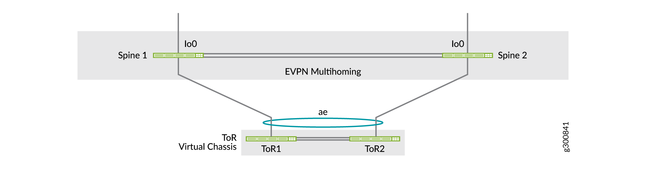
    The ToR layer can contain standalone switches or Virtual Chassis multihomed to the collapsed spine devices. With Virtual Chassis, you can establish redundant links in the ESI-LAGs between the spine devices and different Virtual Chassis member switches to increase resiliency. See Figure 2.

Figure 1 shows a logical view of a collapsed spine data center with border connectivity, DCI between data centers, and Virtual Chassis in the ToR layer multihomed to the spine devices.

Figure 1: Collapsed Spine Data Center With Multihomed Virtual Chassis TOR Devices and Data Center InterconnectCollapsed Spine Data Center With Multihomed Virtual Chassis TOR Devices and Data Center Interconnect

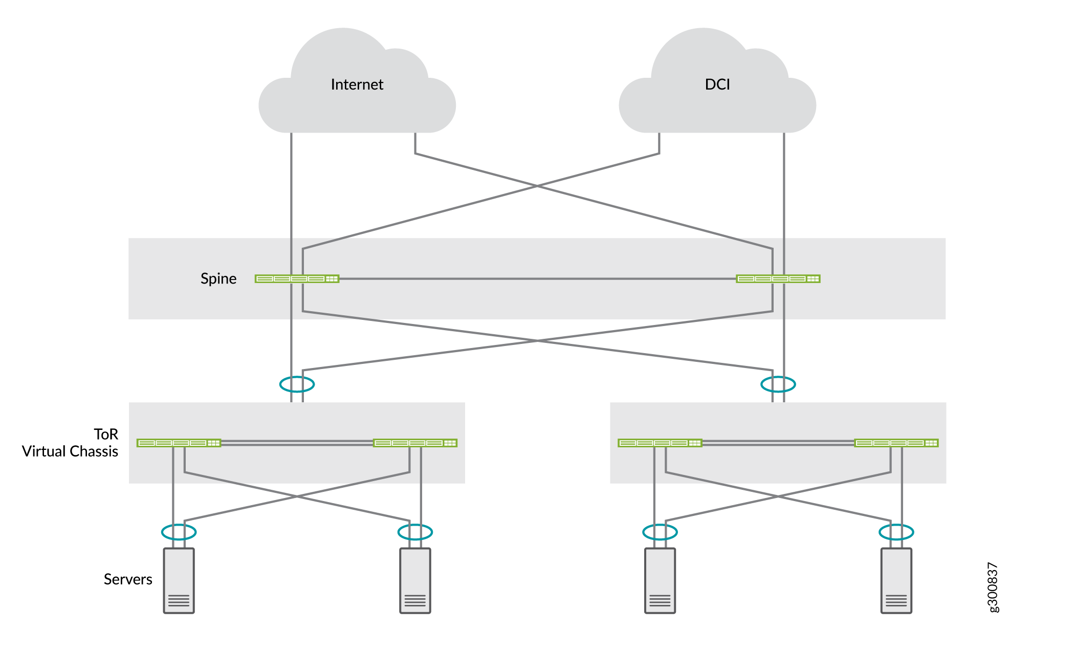
Figure 2 illustrates Virtual Chassis in the ToR layer multihomed to a back-to-back collapsed spine layer, where the spine devices link to different Virtual Chassis member switches to improve ESI-LAG resiliency.

Figure 2: Collapsed Spine Design With Back-to-Back Spine Devices and Multihomed Virtual Chassis in ToR LayerCollapsed Spine Design With Back-to-Back Spine Devices and Multihomed Virtual Chassis in ToR Layer

Refer to Collapsed Spine with EVPN Multihoming, a network configuration example that describes a common collapsed spine use case with back-to-back spine devices. In that example, the ToR devices are Virtual Chassis that are multihomed to the collapsed spine devices. The example includes how to configure additional security services using an SRX chassis cluster to protect inter-tenant traffic, with inter-data center traffic also routed through the SRX cluster as a DCI solution.

Another collapsed spine fabric model interconnects the spine devices through an IP transit layer route reflector cluster that you integrate with the collapsed spine core underlay and overlay networks. Our reference architecture uses this model and is described in the following sections.

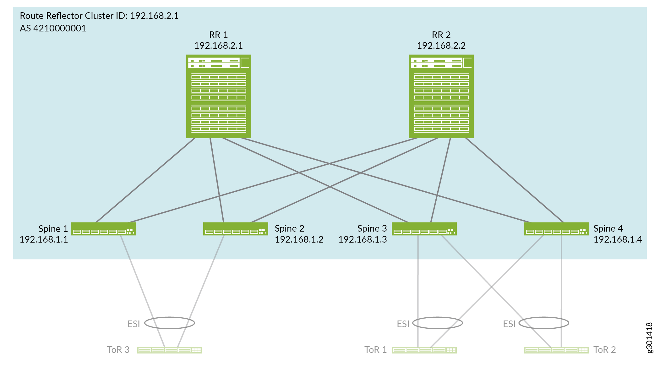
Overview of Collapsed Spine Reference Architecture

Our reference architecture presents a use case for a collapsed spine data center fabric comprising two inter-point of delivery (POD) modules. The PODs and collapsed spine devices in the PODs are interconnected by a super spine IP transit layer configured as a route reflector cluster. See Figure 3. This architecture is similar to a five-stage IP fabric design (see Five-Stage IP Fabric Design and Implementation), but with only the super spine, spine, and access layers. You configure the collapsed spine fabric to integrate the route reflector cluster devices into the IP fabric underlay and EVPN overlay in a similar way.

Figure 3: Collapsed Spine Fabric Integrated With a Route Reflector ClusterCollapsed Spine Fabric Integrated With a Route Reflector Cluster

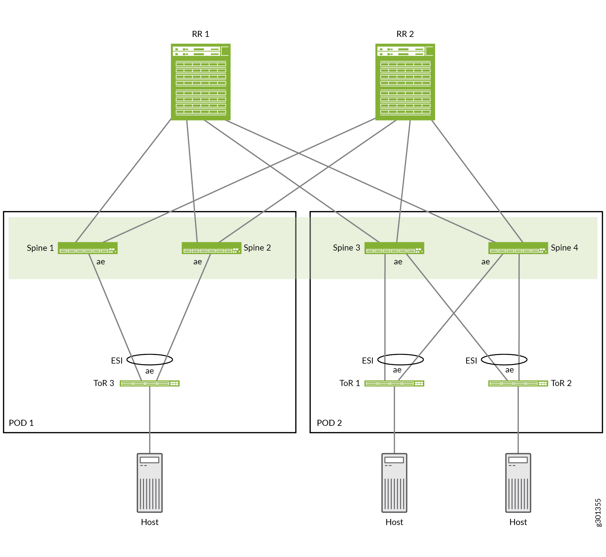
Figure 3 shows an example of the collapsed spine reference design, which includes the following elements:

  • POD 1: ToR 3 multihomed to Spine 1 and Spine 2

  • POD 2: ToR 1 and ToR 2 multihomed to Spine 3 and Spine 4

  • Route reflector cluster: RR 1 and RR 2 interconnecting Spine devices 1 through 4

The four spine devices make up the collapsed spine EVPN fabric core, with Layer 2 stretch and Layer 3 routing between the spine devices in the two PODs. The spine devices in each POD use ESI-LAGs to the multihomed ToR switches in the same POD.

Configure the Collapsed Spine IP Fabric Underlay Integrated With the Route Reflector Layer

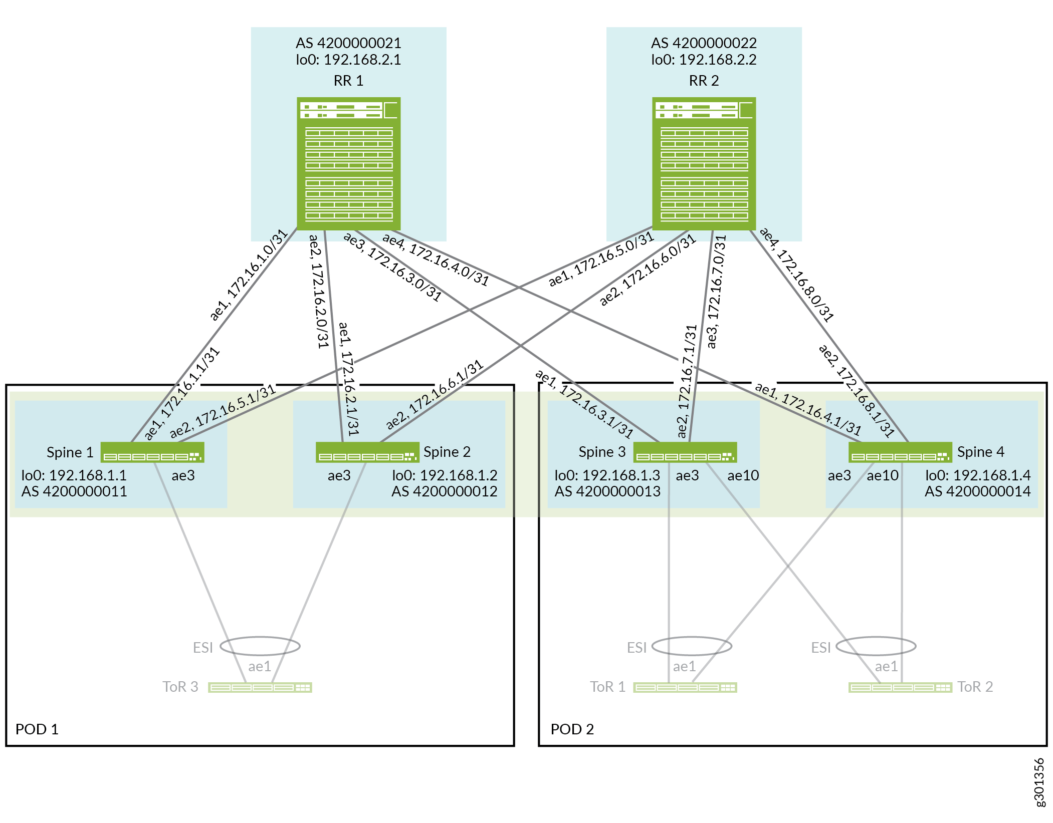
This section describes how to configure the interconnecting links and the IP fabric underlay on the spine and route reflector devices.

Figure 4 shows the collapsed spine and route reflector devices connected by aggregated Ethernet interface links.

Figure 4: Collapsed Spine Reference Architecture Underlay Integrated With Route Reflector ClusterCollapsed Spine Reference Architecture Underlay Integrated With Route Reflector Cluster

To configure the underlay:

  1. Before you configure the interfaces connecting the route reflector and spine devices in the fabric, on each of those devices you must set the number of aggregated Ethernet interfaces you might need on the device. The device assigns unique MAC addresses to each aggregated Ethernet interface you configure.

    Configure the number of aggregated Ethernet interfaces on RR 1, RR 2, Spine 1, Spine 2, Spine 3, and Spine 4 :

  2. Configure the aggregated Ethernet interfaces on the route reflector and spine devices that form the collapsed spine fabric as shown in Figure 4.

    For redundancy, this reference design uses two physical interfaces in each aggregated Ethernet link between the route reflector and spine devices. The route reflector devices link to the four spine devices using aggregated Ethernet interfaces ae1 through ae4. Each spine device uses aggregated Ethernet interfaces ae1 (to RR 1) and ae2 (to RR 2).

    Also, we configure a higher MTU (9192) on the physical interfaces to account for VXLAN encapsulation.

    RR 1:

    RR 2:

    Spine 1:

    Spine 2:

    Spine 3:

    Spine 4:

  3. Configure IP addresses for the loopback interfaces and the router id for each route reflector and spine device, as shown in Figure 4.
  4. On the route reflector and spine devices, configure the EBGP IP fabric underlay. The underlay configuration is similar to other spine and leaf reference architecture designs in IP Fabric Underlay Network Design and Implementation. However, in the underlay in this reference design, the collapsed spine fabric is integrated with the route reflector devices for IP transit functions between the spine devices within and across the PODs.

    The underlay configuration includes the following:

    • Define an export routing policy (underlay-clos-export) that advertises the IP address of the loopback interface to EBGP peering devices. This export routing policy is used to make the IP address of the loopback interface of each device reachable by all devices in the IP fabric (all route reflector and spine devices).

    • Define a local AS number on each device.

    • On the route reflector devices: Identify the four spine devices as the EBGP neighbors by their aggregated Ethernet link IP addresses and local AS numbers.

      On the spine devices: Identify the two route reflector devices as the EBGP neighbors by their aggregated Ethernet link IP addresses and local AS numbers.

    • Turn on BGP peer state transition logging.

    RR 1:

    RR 2:

    Spine 1:

    Spine 2:

    Spine 3:

    Spine 4:

Configure the Collapsed Spine EVPN-VXLAN Overlay Integrated With the Route Reflector Layer

In this design, the overlay is similar to other EVPN-VXLAN data center spine and leaf reference architectures, but doesn’t include a leaf layer. Only the spine devices (integrated with the route reflector cluster) do intra-VLAN and inter-VLAN routing in the fabric. We configure IBGP with Multiprotocol BGP (MP-IBGP) with a single autonomous system (AS) number on the spine devices to establish a signalling path between them by way of the route reflector cluster devices as follows:

  • The route reflector cluster devices peer with the spine devices in both PODs for IP transit.

  • The spine devices peer with the route reflector devices.

See Figure 5, which illustrates the spine and route reflector cluster devices and BGP neighbor IP addresses we configure in the EVPN overlay network.

Figure 5: Collapsed Spine Reference Architecture Overlay Integrated With Route Reflector ClusterCollapsed Spine Reference Architecture Overlay Integrated With Route Reflector Cluster

The overlay configuration is the same on both of the route reflector devices except for the device’s local address (the loopback address). The route reflector devices peer with all of the spine devices.

The overlay configuration is the same on each of the spine devices except for the device’s local address (the loopback address). All of the spine devices peer with the route reflector cluster devices.

We configure EVPN with VXLAN encapsulation and virtual tunnel endpoint (VTEP) interfaces only on the spine devices in the collapsed spine fabric.

To configure the overlay:

  1. Configure an AS number for the IBGP overlay on all spine and route reflector devices:
  2. Configure IBGP with EVPN signaling on the route reflector devices to peer with the collapsed spine devices, identified as IBGP neighbors by their device loopback addresses as illustrated in Figure 5.

    In this step, you also:

    • Define RR 1 and RR 2 as a route reflector cluster (with cluster ID 192.168.2.1).

    • Enable path maximum transmission unit (MTU) discovery to dynamically determine the MTU size on the network path between the source and the destination, which can help avoid IP fragmentation.

    • Set up Bidirectional Forwarding Detection (BFD) for detecting IBGP neighbor failures.

    • Set the vpn-apply-export option to ensure that both the VRF and BGP group or neighbor export policies in the BGP configuration are applied (in that order) before the device advertises routes in the VPN routing tables to the other route reflector or spine devices. (See Distributing VPN Routes for more information.)

    RR 1:

    RR 2:

  3. Configure IBGP with EVPN on the collapsed spine devices to peer with the route reflector devices, which are identified as IBGP neighbors by their device loopback addresses shown in Figure 5. The configuration is the same on all spine devices except you substitute the spine device’s loopback IP address for the local-address device-loopback-addr value.

    In this step you also:

    • Enable path maximum transmission unit (MTU) discovery to dynamically determine the MTU size on the network path between the source and the destination, which can help avoid IP fragmentation.

    • Set up BFD for detecting IBGP neighbor failures.

    • Set the vpn-apply-export option to ensure that both the VRF and BGP group or neighbor export policies in the BGP configuration are applied (in that order) before the device advertises routes in the VPN routing tables to the other route reflector or spine devices. (See Distributing VPN Routes for more information.)

    All spine devices:

  4. Ensure LLDP is enabled on all interfaces except the management interface (em0) on the route reflector cluster and spine devices.

    All route reflector and spine devices:

  5. Configure EVPN with VXLAN encapsulation in the overlay on the spine devices. The configuration is the same on all spine devices in the collapsed spine fabric.

    In this step:

    • Specify and apply a policy for per-packet load balancing for ECMP in the forwarding table.

    • Configure these EVPN options at the [edit protocols evpn] hierarchy level along with setting VXLAN encapsulation:

      • default-gateway no-gateway-community: Advertise the virtual gateway and IRB MAC addresses to the EVPN peer devices so that Ethernet-only edge devices can learn these MAC addresses. You configure no-gateway-community in a collapsed spine fabric if the spines use:

      • extended-vni-list all option: Allow all configured VXLAN network identifiers (VNIs) to be part of this EVPN-VXLAN BGP domain. We configure VLANs and VLAN to VNI mappings in a later section.

      • remote-ip-host-routes: Enable virtual machine traffic optimization (VMTO). (See Ingress Virtual Machine Traffic Optimization for EVPN for more information.)

    All spine devices:

  6. Configure VTEP, route target, and virtual routing and forwarding (VRF) switch options on the spine devices.

    The configuration is the same on all spine devices except on each device you substitute the device’s loopback IP address for the route-distinguisher value. This value defines a unique route distinguisher for routes generated by each device.

    The VTEP source interface in the EVPN instance should also match the IBGP local peer address, which is likewise the device loopback IP address.

    Spine 1:

    Spine 2:

    Spine 3:

    Spine 4:

  7. (Required on PTX10000 Series routers only) Enable tunnel termination globally (in other words, on all interfaces) on the device:

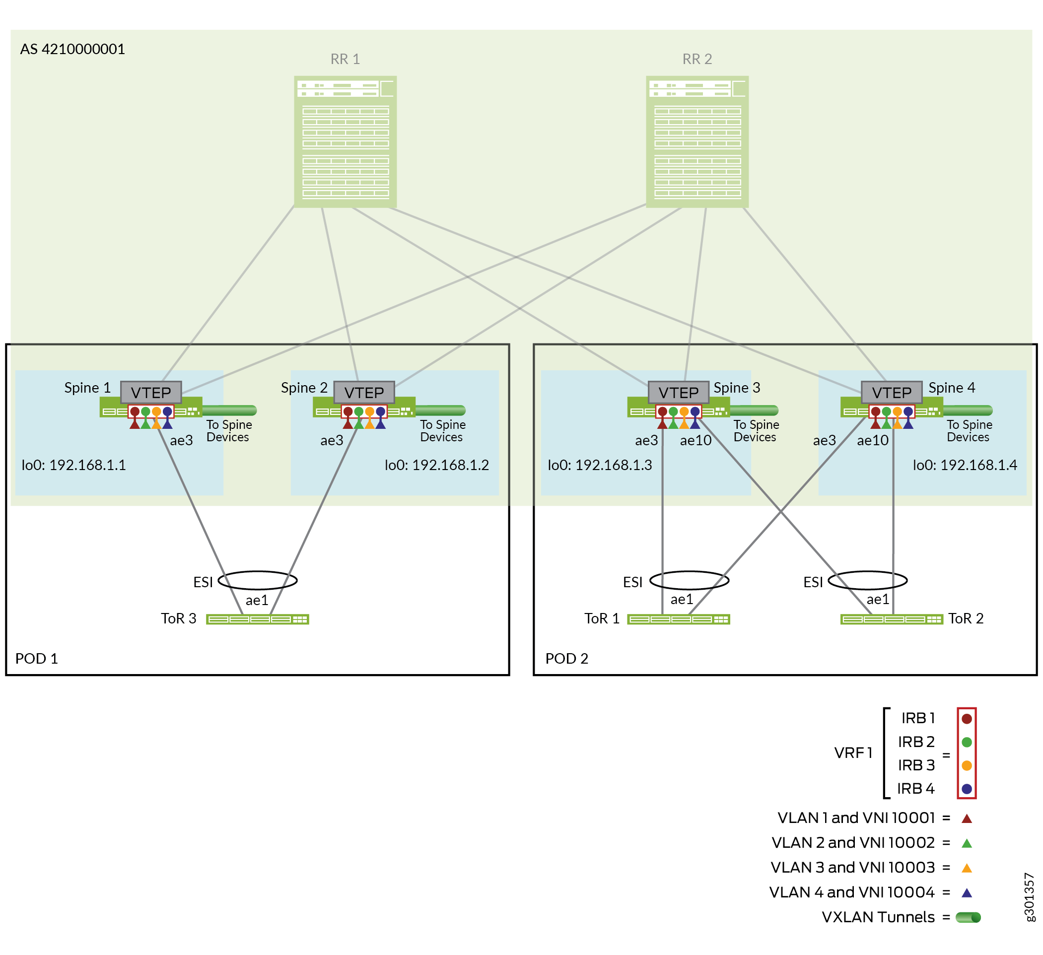
Configure EVPN Multihoming and Virtual Networks on the Spine Devices for the ToR Switches

This collapsed spine reference design implements EVPN multihoming as described in Multihoming an Ethernet-Connected End System Design and Implementation, except because the leaf layer functions are collapsed into the spine layer, you configure the ESI-LAGs on the spine devices. You also configure VLANs and Layer 2 and Layer 3 routing functions on the spine devices in a similar way as you would on the leaf devices in an edge-routed bridging (ERB) overlay design. The core collapsed spine configuration implements a Layer 2 stretch by setting the same VLANs (and VLAN-to-VNI mappings) on all of the spine devices in both PODs. EVPN Type 2 routes enable communication between endpoints within and across the PODs.

Figure 6 shows the collapsed spine devices in each POD connected with aggregated Ethernet interface links to the multihomed ToR switches in the POD.

Figure 6: Collapsed Spine Fabric With Multihomed ToR SwitchesCollapsed Spine Fabric With Multihomed ToR Switches

For brevity, this section illustrates one aggregated Ethernet link between each spine and each ToR device, with one interface configured on each aggregated Ethernet link from the spine devices to the ToR devices in the POD.

This section covers configuration details only for the spine and ToR devices in POD 2. You can apply a similar configuration with applicable device parameters and interfaces to the spine and ToR devices in POD 1.

The ToR devices include two interfaces in their aggregated Ethernet links, one to each spine device in the POD that form the ESI-LAG for multihoming.

The configuration includes steps to:

  • Configure the interfaces.

  • Set up the ESI-LAGs for EVPN multihoming.

  • Configure Layer 2 and Layer 3 gateway functions, including defining VLANs, the associated IRB interfaces for inter-VLAN routing, and corresponding VLAN-to-VNI mappings.

  1. Configure the interfaces and aggregated Ethernet links on the spines (Spine 3 and Spine 4) to the multihomed ToR switches (ToR 1 and ToR 2) in POD 2.

    Spine 3:

    Spine 4:

  2. Configure the ESI-LAGs for EVPN multihoming on the spine devices for the multihomed ToR switches in POD 2. This design uses the same aggregated Ethernet interfaces on the spine devices to the ToR switches, so you use the same configuration on both devices.

    In this reference design, ae3 connects to ToR 1 and ae10 connects to ToR 2.

    Spine 3 and Spine 4:

  3. Configure VLANs on the spine devices in POD 2 with ae3 and ae10 as VLAN members.

    Spine 3 and Spine 4:

  4. Map the VLANs to VNIs for the VXLAN tunnels and associate an IRB interface with each one.

    Spine 3 and Spine 4:

  5. Configure the IRB interfaces for the VLANs (VNIs) on the spine devices in POD 2 with IPv4 and IPv6 dual stack addresses for both the IRB IP address and virtual gateway IP address.

    Spine 3:

    Spine 4:

  6. Define the VRF routing instance and corresponding IRB interfaces for EVPN Type 2 routes on each spine device in POD 2 for the configured VLANs (VNIs).

    Spine 3:

    Spine 4:

  7. Configure the interfaces and aggregated Ethernet links on the multihomed ToR switches (ToR 1 and ToR 2) to the spine devices (Spine 3 and Spine 4) in POD 2. In this step, you:
    • Set the number of aggregated Ethernet interfaces on the switch that you might need (we set 20 here as an example).

    • Configure aggregated Ethernet link ae1 on each ToR switch to the spine devices in POD 2.

    • Configure LLDP on the interfaces.

    ToR 1:

    ToR 2:

  8. Configure the VLANs on the ToR switches in POD 2. These match the VLANs you configured in Step 3 on the spine devices in POD 2.

    ToR 1 and ToR 2:

Verify Collapsed Spine Fabric Connectivity With Route Reflector Cluster and ToR Devices

This section shows CLI commands you can use to verify connectivity between the collapsed spine devices and the route reflector cluster, and between the collapsed spine devices and the ToR devices.

For brevity, this section includes verifying connectivity on the spine devices using only Spine 3 and Spine 4 in POD 2. You can use the same commands on the spine devices (Spine 1 and Spine 2) in POD 1.

  1. Verify connectivity on the aggregated Ethernet links on the route reflector devices toward the four collapsed spine devices. On each route reflector device, aeX connects to Spine X).

    RR 1:

    RR 2:

  2. Verify connectivity on the aggregated Ethernet links on the spine devices in POD 2 (Spine 3 and Spine 4) toward the route reflector devices. Links ae1 and ae2 connect to route reflector devices RR 1 and RR 2, respectively, on both Spine 3 and Spine 4.

    Spine 3:

    Spine 4:

  3. Verify connectivity on the aggregated Ethernet links on the spine devices in POD 2 (Spine 3 and Spine 4) toward the multihomed ToR switches. Links ae3 and ae10 connect to ToR 1 and ToR 2, respectively, on both Spine 3 and Spine 4, so this command line filters the output to find link states starting with ae3. The output is truncated to show status only for the relevant links.

    Spine 3:

    Spine 4:

  4. Verify that the spine devices in POD 2 (Spine 3 and Spine 4) detect the route reflector devices and the ToR switches in POD 2 as LLDP neighbors. For the spine to ToR links, this verifies that the ESI member links have been established to the multihomed ToR switches.

    This sample command output is filtered and truncated to show only the relevant aggregated Ethernet links. Comment lines show the columns for the values displayed in the resulting output. See Figure 4 again, which shows that both spine switches in POD 2 use ae1 and ae2 to link to the route reflector devices, ae3 to link to ToR1, and ae10 to link to ToR 2.

    Spine 3:

    Spine 4:

Verify Collapsed Spine Fabric BGP Underlay and EVPN-VXLAN Overlay Configuration

This section shows CLI commands you can use to verify the underlay and overlay are working for the collapsed spine devices integrated with the route reflector cluste. Refer to Figure 4 and Figure 5 again for the configured underlay and overlay parameters.

For brevity, this section includes verifying connectivity on the spine devices using only Spine 3 and Spine 4 in POD 2. You can use the same commands on the spine devices (Spine 1 and Spine 2) in POD 1.

  1. Verify on the route reflector devices that the EBGP and IBGP peering is established and traffic paths with the four spine devices are active. This sample command output is filtered to show only the relevant status lines showing the established peering. Comment lines show the columns for the values displayed in the resulting output.

    RR 1:

    RR 2:

  2. Verify on the spine devices in POD 2 that the underlay EBGP and overlay IBGP peerings are established. This sample command output is filtered to show only the relevant status lines showing the established peering. Comment lines show the columns for the values displayed in the resulting output.

    Spine 3:

    Spine 4:

  3. Verify the endpoint destination IP addresses for the remote VTEP interfaces, which are the loopback addresses of the other three spine devices in POD 1 and POD 2 of this collapsed spine topology. We include sample output for Spine 3 in POD 2 here; results are similar on the other spine devices.

    Spine 3:

  4. Verify the ESI-LAGs on the spine devices toward the ToR switches. We include sample output here for Spine 3 in POD 2 here; results are similar on the other spine devices.

    Spine 3: