Multihoming an Ethernet-Connected End System Design and Implementation
For an overview of multihoming an Ethernet-connected end system in this reference design, see the Multihoming Support for Ethernet-Connected End Systems section in Data Center Fabric Blueprint Architecture Components.
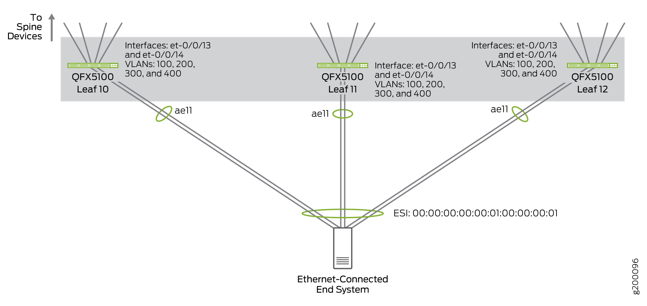
Figure 1 illustrates the multihomed Ethernet-connected end system in this procedure:
Configuring a Multihomed Ethernet-Connected End System using EVPN Multihoming with VLAN Trunking
EVPN multihoming is used in this building block to connect an Ethernet-connected end system into the overlay network. EVPN multihoming works by treating two or more physical multihomed links as a single Ethernet segment identified by an EVPN Ethernet Segment ID (ESI). The set of physical links belonging to the same Ethernet segment are treated as one aggregated Ethernet interface. The member links—much like member links in a traditional aggregated Ethernet interface—provide redundant paths to and from the end system while also ensuring overlay network traffic is load-balanced across the multiple paths.
LACP with the fast timer mode is used to improve fault detection and disablement of impaired members of an Ethernet segment. MicroBFD may also be used to further improve fault isolation but may not scale to support all end-system facing ports. Furthermore, support for microBFD must exist at the end system.
The reference design tested an Ethernet-connected server was connected to a single leaf or multihomed to 2 or 3 leaf devices to verify that traffic can be properly handled in multihomed setups with more than 2 leaf devices; in practice, an Ethernet-connected server can be multihomed to a large number of leaf devices.
To configure a multihomed Ethernet-connected server:
Enabling Storm Control
Storm control can be enabled as part of this building block. Storm control is used to prevent BUM traffic storms by monitoring BUM traffic levels and taking a specified action to limit BUM traffic forwarding when a specified traffic level—called the storm control level—is exceeded. See Understanding Storm Control for additional information on the feature.
In this reference design, storm control is enabled on server-facing aggregated Ethernet interfaces to rate limit broadcast, unknown unicast, and multicast (BUM) traffic. If the amount of BUM traffic exceeds 1% of the available bandwidth on the aggregated Ethernet interface, storm control drops BUM traffic to prevent broadcast storms.
To enable storm control:
Multihoming a Ethernet-Connected End System—Release History
Table 1 provides a history of all of the features in this section and their support within this reference design.
Release |
Description |
|---|---|
19.1R2 |
QFX10002-60C and QFX5120-32C switches running Junos OS Release 19.1R2 and later releases in the same release train support all features documented in this section. |
18.4R2 |
QFX5120-48Y switches running Junos OS Release 18.4R2 and later releases in the same release train support all features documented in this section. |
18.1R3-S3 |
QFX5110 switches running Junos OS Release 18.1R3-S3 and later releases in the same release train support all features documented in this section. |
17.3R3-S1 |
All devices in the reference design that support Junos OS Release 17.3R3-S1 and later releases in the same release train also support all features documented in this section. |