ON THIS PAGE
Configuring the Delay Before LDP Neighbors Are Considered Down
Configuring the Prefixes Advertised into LDP from the Routing Table
Configuring a Failure Action for the BFD Session on an LDP LSP
Example: Configuring Multicast-Only Fast Reroute in a Multipoint LDP Domain
Example: Configuring Multipoint LDP In-Band Signaling for Point-to-Multipoint LSPs
Mapping Client and Server for Segment Routing to LDP Interoperability
LDP Configuration
Minimum LDP Configuration
To enable LDP with minimal configuration:
Enable all relevant interfaces under family MPLS. In the case of directed LDP, the loopback interface needs to be enabled with family MPLS.
(Optional) Configure the relevant interfaces under the
[edit protocol mpls]hierarchy level.Enable LDP on a single interface, include the
ldpstatement and specify the interface using theinterfacestatement.
This is the minimum LDP configuration. All other LDP configuration statements are optional.
ldp {
    interface interface-name;
}
To enable LDP on all interfaces, specify all for interface-name.
For a list of hierarchy levels at which you can include these statements, see the statement summary sections.
Enabling and Disabling LDP
LDP is routing-instance-aware. To enable LDP on a specific interface, include the following statements:
ldp {
    interface interface-name;
}
For a list of hierarchy levels at which you can include these statements, see the statement summary sections.
To enable LDP on all interfaces, specify all for interface-name.
If you have configured interface properties on a group of interfaces
and want to disable LDP on one of the interfaces, include the interface statement with the disable option:
interface interface-name {
    disable;
}
For a list of hierarchy levels at which you can include this statement, see the statement summary section.
Configuring the LDP Timer for Hello Messages
LDP hello messages enable LDP nodes to discover one another and to detect the failure of a neighbor or the link to the neighbor. Hello messages are sent periodically on all interfaces where LDP is enabled.
There are two types of LDP hello messages:
Link hello messages—Sent through the LDP interface as UDP packets addressed to the LDP discovery port. Receipt of an LDP link hello message on an interface identifies an adjacency with the LDP peer router.
Targeted hello messages—Sent as UDP packets addressed to the LDP discovery port at a specific address. Targeted hello messages are used to support LDP sessions between routers that are not directly connected. A targeted router determines whether to respond or ignore a targeted hello message. A targeted router that chooses to respond does so by periodically sending targeted hello messages back to the initiating router.
By default, LDP sends hello messages every 5 seconds for link hello messages and every 15 seconds for targeted hello messages. You can configure the LDP timer to alter how often both types of hello messages are sent. However, you cannot configure a time for the LDP timer that is greater than the LDP hold time. For more information, see Configuring the Delay Before LDP Neighbors Are Considered Down.
- Configuring the LDP Timer for Link Hello Messages
- Configuring the LDP Timer for Targeted Hello Messages
Configuring the LDP Timer for Link Hello Messages
To modify how often LDP sends link hello messages, specify a
new link hello message interval for the LDP timer using the hello-interval statement:
hello-interval seconds;
For a list of hierarchy levels at which you can include this statement, see the statement summary section for this statement.
Configuring the LDP Timer for Targeted Hello Messages
To modify how often LDP sends targeted hello messages, specify
a new targeted hello message interval for the LDP timer by configuring
the hello-interval statement as an option for the targeted-hello statement:
targeted-hello {
    hello-interval seconds;
}
For a list of hierarchy levels at which you can include these statements, see the statement summary sections for these statements.
Configuring the Delay Before LDP Neighbors Are Considered Down
The hold time determines how long an LDP node should wait for a hello message before declaring a neighbor to be down. This value is sent as part of a hello message so that each LDP node tells its neighbors how long to wait. The values sent by each neighbor do not have to match.
The hold time should normally be at least three times the hello interval. The default is 15 seconds for link hello messages and 45 seconds for targeted hello messages. However, it is possible to configure an LDP hold time that is close to the value for the hello interval.
By configuring an LDP hold time close to the hello interval (less than three times the hello interval), LDP neighbor failures might be detected more quickly. However, this also increases the possibility that the router might declare an LDP neighbor down that is still functioning normally. For more information, see Configuring the LDP Timer for Hello Messages.
The LDP hold time is also negotiated automatically between LDP peers. When two LDP peers advertise different LDP hold times to one another, the smaller value is used. If an LDP peer router advertises a shorter hold time than the value you have configured, the peer router’s advertised hold time is used. This negotiation can affect the LDP keepalive interval as well.
If the local LDP hold time is not shortened during LDP peer negotiation, the user-configured keepalive interval is left unchanged. However, if the local hold time is reduced during peer negotiation, the keepalive interval is recalculated. If the LDP hold time has been reduced during peer negotiation, the keepalive interval is reduced to one-third of the new hold time value. For example, if the new hold-time value is 45 seconds, the keepalive interval is set to 15 seconds.
This automated keepalive interval calculation can cause different keepalive intervals to be configured on each peer router. This enables the routers to be flexible in how often they send keepalive messages, because the LDP peer negotiation ensures they are sent more frequently than the LDP hold time.
When you reconfigure the hold-time interval, changes do not
take effect until after the session is reset. The hold time is negotiated
when the LDP peering session is initiated and cannot be renegotiated
as long as the session is up (required by RFC 5036, LDP Specification). To manually force the LDP session
to reset, issue the clear ldp session command.
- Configuring the LDP Hold Time for Link Hello Messages
- Configuring the LDP Hold Time for Targeted Hello Messages
Configuring the LDP Hold Time for Link Hello Messages
To modify how long an LDP node should wait for a link hello
message before declaring the neighbor down, specify a new time in
seconds using the hold-time statement:
hold-time seconds;
For a list of hierarchy levels at which you can include this statement, see the statement summary section for this statement.
Configuring the LDP Hold Time for Targeted Hello Messages
To modify how long an LDP node should wait for a targeted hello
message before declaring the neighbor down, specify a new time in
seconds using the hold-time statement as an option for
the targeted-hello statement:
targeted-hello {
    hold-time seconds;
}
For a list of hierarchy levels at which you can include these statements, see the statement summary sections for these statements.
Enabling Strict Targeted Hello Messages for LDP
Use strict targeted hello messages to prevent LDP sessions
from being established with remote neighbors that have not been specifically
configured. If you configure the strict-targeted-hellos statement, an LDP peer does not respond to targeted hello messages
coming from a source that is not one of its configured remote neighbors.
Configured remote neighbors can include:
Endpoints of RSVP tunnels for which LDP tunneling is configured
Layer 2 circuit neighbors
If an unconfigured neighbor sends a hello message, the
LDP peer ignores the message and logs an error (with the error trace flag) indicating the source. For example, if the LDP peer
received a targeted hello from the Internet address 10.0.0.1 and no
neighbor with this address is specifically configured, the following
message is printed to the LDP log file:
LDP: Ignoring targeted hello from 10.0.0.1
To enable strict targeted hello messages, include the strict-targeted-hellos statement:
strict-targeted-hellos;
For a list of hierarchy levels at which you can include this statement, see the statement summary section for this statement.
Configuring the Interval for LDP Keepalive Messages
The keepalive interval determines how often a message is sent over the session to ensure that the keepalive timeout is not exceeded. If no other LDP traffic is sent over the session in this much time, a keepalive message is sent. The default is 10 seconds. The minimum value is 1 second.
The value configured for the keepalive interval can be altered during LDP session negotiation if the value configured for the LDP hold time on the peer router is lower than the value configured locally. For more information, see Configuring the Delay Before LDP Neighbors Are Considered Down.
To modify the keepalive interval, include the keepalive-interval statement:
keepalive-interval seconds;
For a list of hierarchy levels at which you can include this statement, see the statement summary section for this statement.
Configuring the LDP Keepalive Timeout
After an LDP session is established, messages must be exchanged periodically to ensure that the session is still working. The keepalive timeout defines the amount of time that the neighbor LDP node waits before deciding that the session has failed. This value is usually set to at least three times the keepalive interval. The default is 30 seconds.
To modify the keepalive interval, include the keepalive-timeout statement:
keepalive-timeout seconds;
For a list of hierarchy levels at which you can include this statement, see the statement summary section for this statement.
The value configured for the keepalive-timeout statement
is displayed as the hold time when you issue the show ldp session
detail command.
Configuring Longest Match for LDP
In order to allow LDP to learn the routes aggregated or summarized across OSPF areas or IS-IS levels in inter -domain, Junos OS allows you to configure longest match for LDP based on RFC5283.
Before you configure longest match for LDP, you must do the following:
Configure the device interfaces.
Configure the MPLS protocol.
Configure the OSPF protocol.
To configure longest match for LDP, you must do the following:
Example: Configuring Longest Match for LDP
This example shows how to configure longest match for LDP based on RFC5283. This allows LDP to learn the routes aggregated or summarized across OSPF areas or IS-IS levels in inter-domain.. The longest match policy provides per prefix granularity.
Requirements
This example uses the following hardware and software components:
Six MX Series routers with OSPF protocol, and LDP enabled on the connected interfaces.
Junos OS Release 16.1 or later running on all devices.
Before you begin:
Configure the device interfaces.
Configure OSPF.
Overview
LDP is often used to establish MPLS label-switched paths (LSPs)
throughout a complete network domain using an IGP such as OSPF or
IS-IS. In such a network, all links in the domain have IGP adjacencies
as well as LDP adjacencies. LDP establishes the LSPs on the shortest
path to a destination as determined by IP forwarding. In Junos OS,
the LDP implementation does an exact match lookup on the IP address
of the FEC in the RIB or IGP routes for label mapping. This exact
mapping requires MPLS end-to-end LDP endpoint IP addresses to be configured
in all the LERs. This defeats the purpose of IP hierarchical design
or default routing in access devices. Configuring longest-match helps to overcome this by suppressing the exact match behaviour
and setup LSP based on the longest matching route on per-prefix basis.
Topology
In the topology, Figure 1shows the longest match for LDP is configured on Device R0 .
Configuration
CLI Quick Configuration
To quickly configure this example, copy the
following commands, paste them into a text file, remove any line breaks,
change any details necessary to match your network configuration,
copy and paste the commands into the CLI at the [edit] hierarchy level, and then enter commit from configuration
mode.
R0
set interfaces ge-0/0/0 unit 0 family inet address 22.22.22.1/24 set interfaces ge-0/0/1 unit 0 family inet address 15.15.15.1/24 set interfaces ge-0/0/2 unit 0 family inet address 11.11.11.1/24 set interfaces ge-0/0/2 unit 0 family iso set interfaces ge-0/0/2 unit 0 family mpls set interfaces lo0 unit 0 family inet address 10.255.112.1/32 primary set interfaces lo0 unit 0 family inet address 10.255.112.1/32 preferred set interfaces lo0 unit 0 family iso address 49.0002.0192.0168.0001.00 set routing-options router-id 10.255.112.1 set protocols mpls interface ge-0/0/2.0 set protocols ospf area 0.0.0.1 interface ge-0/0/2.0 set protocols ospf area 0.0.0.1 interface lo0.0 passive set protocols ldp longest-match set protocols ldp interface ge-0/0/2.0 set protocols ldp interface lo0.0
R1
set interfaces ge-0/0/0 unit 0 family inet address 11.11.11.2/24 set interfaces ge-0/0/0 unit 0 family iso set interfaces ge-0/0/0 unit 0 family mpls set interfaces ge-0/0/1 unit 0 family inet address 12.12.12.1/24 set interfaces ge-0/0/1 unit 0 family iso set interfaces ge-0/0/1 unit 0 family mpls set interfaces lo0 unit 0 family inet address 10.255.112.2/32 primary set interfaces lo0 unit 0 family inet address 10.255.112.2/32 preferred set interfaces lo0 unit 0 family iso address 49.0002.0192.0168.0002.00 set routing-options router-id 10.255.112.2 set protocols mpls interface ge-0/0/0.0 set protocols mpls interface ge-0/0/1.0 set protocols ospf area 0.0.0.0 interface ge-0/0/1.0 set protocols ospf area 0.0.0.0 interface lo0.0 passive set protocols ospf area 0.0.0.1 interface ge-0/0/0.0 set protocols ldp longest-match set protocols ldp interface ge-0/0/0.0 set protocols ldp interface ge-0/0/1.0 set protocols ldp interface lo0.0
R2
set interfaces ge-0/0/0 unit 0 family inet address 24.24.24.1/24 set interfaces ge-0/0/0 unit 0 family iso set interfaces ge-0/0/0 unit 0 family mpls set interfaces ge-0/0/1 unit 0 family inet address 12.12.12.2/24 set interfaces ge-0/0/1 unit 0 family iso set interfaces ge-0/0/1 unit 0 family mpls set interfaces ge-0/0/2 unit 0 family inet address 23.23.23.1/24 set interfaces ge-0/0/2 unit 0 family iso set interfaces ge-0/0/2 unit 0 family mpls set interfaces ge-0/0/3 unit 0 family inet address 22.22.22.2/24 set interfaces ge-0/0/4 unit 0 family inet address 25.25.25.1/24 set interfaces ge-0/0/4 unit 0 family iso set interfaces ge-0/0/4 unit 0 family mpls set interfaces lo0 unit 0 family inet address 10.255.111.4/32 primary set interfaces lo0 unit 0 family inet address 10.255.111.4/32 preferred set interfaces lo0 unit 0 family iso address 49.0003.0192.0168.0003.00 set routing-options router-id 10.255.111.4 set protocols mpls interface ge-0/0/1.0 set protocols mpls interface ge-0/0/2.0 set protocols mpls interface ge-0/0/0.0 set protocols mpls interface ge-0/0/4.0 set protocols ospf area 0.0.0.0 interface ge-0/0/1.0 set protocols ospf area 0.0.0.0 interface lo0.0 passive set protocols ospf area 0.0.0.2 area-range 10.255.111.0/24 set protocols ospf area 0.0.0.2 interface ge-0/0/2.0 set protocols ospf area 0.0.0.2 interface ge-0/0/0.0 set protocols ospf area 0.0.0.2 interface ge-0/0/4.0 set protocols ldp interface ge-0/0/0.0 set protocols ldp interface ge-0/0/1.0 set protocols ldp interface ge-0/0/2.0 set protocols ldp interface ge-0/0/4.0 set protocols ldp interface lo0.0
R3
set interfaces ge-0/0/0 unit 0 family inet address 35.35.35.1/24 set interfaces ge-0/0/0 unit 0 family iso set interfaces ge-0/0/0 unit 0 family mpls set interfaces ge-0/0/1 unit 0 family inet address 23.23.23.2/24 set interfaces ge-0/0/1 unit 0 family iso set interfaces ge-0/0/1 unit 0 family mpls set interfaces ge-0/0/2 unit 0 family inet address 34.34.34.1/24 set interfaces ge-0/0/2 unit 0 family iso set interfaces ge-0/0/2 unit 0 family mpls set interfaces lo0 unit 0 family inet address 10.255.111.1/32 primary set interfaces lo0 unit 0 family inet address 10.255.111.1/32 preferred set interfaces lo0 unit 0 family iso address 49.0003.0192.0168.0004.00 set routing-options router-id 10.255.111.1 set protocols mpls interface ge-0/0/1.0 set protocols ospf area 0.0.0.2 interface ge-0/0/1.0 set protocols ospf area 0.0.0.2 interface fxp0.0 disable set protocols ospf area 0.0.0.2 interface lo0.0 passive set protocols ldp interface ge-0/0/1.0 set protocols ldp interface lo0.0
R4
set interfaces ge-0/0/0 unit 0 family inet address 45.45.45.1/24 set interfaces ge-0/0/0 unit 0 family iso set interfaces ge-0/0/0 unit 0 family mpls set interfaces ge-0/0/1 unit 0 family inet address 24.24.24.2/24 set interfaces ge-0/0/1 unit 0 family iso set interfaces ge-0/0/1 unit 0 family mpls set interfaces ge-0/0/2 unit 0 family inet address 34.34.34.2/24 set interfaces ge-0/0/2 unit 0 family iso set interfaces ge-0/0/2 unit 0 family mpls set interfaces lo0 unit 0 family inet address 10.255.111.2/32 primary set interfaces lo0 unit 0 family inet address 10.255.111.2/32 preferred set interfaces lo0 unit 0 family iso address 49.0003.0192.0168.0005.00 set routing-options router-id 10.255.111.2 set protocols mpls interface ge-0/0/1.0 set protocols ospf area 0.0.0.2 interface ge-0/0/1.0 set protocols ospf area 0.0.0.2 interface fxp0.0 disable set protocols ospf area 0.0.0.2 interface lo0.0 passive set protocols ldp interface ge-0/0/1.0 set protocols ldp interface lo0.0
R5
set interfaces ge-0/0/0 unit 0 family inet address 25.25.25.2/24 set interfaces ge-0/0/0 unit 0 family iso set interfaces ge-0/0/0 unit 0 family mpls set interfaces ge-0/0/1 unit 0 family inet address 15.15.15.2/24 set interfaces ge-0/0/2 unit 0 family inet address 35.35.35.2/24 set interfaces ge-0/0/3 unit 0 family inet address 45.45.45.2/24 set interfaces ge-0/0/3 unit 0 family iso set interfaces ge-0/0/3 unit 0 family mpls set interfaces lo0 unit 0 family inet address 10.255.111.3/32 primary set interfaces lo0 unit 0 family inet address 10.255.111.3/32 preferred set interfaces lo0 unit 0 family iso address 49.0003.0192.0168.0006.00 set routing-options router-id 10.255.111.3 set protocols mpls interface ge-0/0/0.0 set protocols ospf area 0.0.0.2 interface ge-0/0/0.0 set protocols ospf area 0.0.0.2 interface fxp0.0 disable set protocols ospf area 0.0.0.2 interface lo0.0 passive set protocols ldp interface ge-0/0/0.0 set protocols ldp interface lo0.0
Configuring Device R0
Step-by-Step Procedure
The following example requires that you navigate various levels in the configuration hierarchy. For information about navigating the CLI, see Using the CLI Editor in Configuration Mode in the CLI User Guide.
To configure Device R0:
Configure the interfaces.
[edit interfaces] set ge-0/0/0 unit 0 family inet address 22.22.22.1/24 set ge-0/0/1 unit 0 family inet address 15.15.15.1/24 set ge-0/0/2 unit 0 family inet address 11.11.11.1/24 set ge-0/0/2 unit 0 family iso set ge-0/0/2 unit 0 family mpls
Assign the loopback addresses to the device.
[edit interfaces lo0 unit 0 family] set inet address 10.255.112.1/32 primary set inet address 10.255.112.1/32 preferred set iso address 49.0002.0192.0168.0001.00
Configure the router ID.
[edit routing-options] set router-id 10.255.112.1
Configure the MPLS protocol on the interface.
[edit protocols mpls] set interface ge-0/0/2.0
Configure the OSPF protocol on the interface.
[edit protocols ospf] set area 0.0.0.1 interface ge-0/0/2.0 set area 0.0.0.1 interface lo0.0 passive
Configure longest match for the LDP protocol.
[edit protocols ldp] set longest-match
Configure the LDP protocol on the interface.
[edit protocols ldp] set interface ge-0/0/2.0 set interface lo0.0
Results
From configuration mode, confirm your configuration by entering the show interfaces, show protocols, and show routing-options commands. If the output does not display the intended configuration, repeat the instructions in this example to correct the configuration.
user@R0# show interfaces
ge-0/0/0 {
unit 0 {
family inet {
address 22.22.22.1/24;
}
}
}
ge-0/0/1 {
unit 0 {
family inet {
address 15.15.15.1/24;
}
}
}
ge-0/0/2 {
unit 0 {
family inet {
address 11.11.11.1/24;
}
family iso;
family mpls;
}
}
lo0 {
unit 0 {
family inet {
address 10.255.112.1/32 {
primary;
preferred;
}
}
family iso {
address 49.0002.0192.0168.0001.00;
}
}
}
user@R0# show protocols
mpls {
interface ge-0/0/2.0;
}
ospf {
area 0.0.0.1 {
interface ge-0/0/2.0;
interface lo0.0 {
passive;
}
}
}
ldp {
longest-match;
interface ge-0/0/2.0;
interface lo0.0;
}
user@R0# show routing-options router-id 10.255.112.1;
If you are done configuring the device, enter commit from the configuration mode.
Verification
Confirm that the configuration is working properly.
- Verifying the Routes
- Verifying LDP Overview Information
- Verify the LDP Entries in the Internal Topology Table
- Verify Only FEC Information of LDP Route
- Verify FEC and Shadow Routes of LDP
Verifying the Routes
Purpose
Verify that the expected routes are learned.
Action
On Device R0, from operational mode, run the show
route command to display the routes in the routing table.
user@R0> show route
inet.0: 62 destinations, 62 routes (62 active, 0 holddown, 0 hidden)
+ = Active Route, - = Last Active, * = Both
10.4.0.0/16 *[Static/5] 10:08:01
> to 10.92.31.254 via fxp0.0
10.5.0.0/16 *[Static/5] 10:08:01
> to 10.92.31.254 via fxp0.0
10.6.128.0/17 *[Static/5] 10:08:01
> to 10.92.31.254 via fxp0.0
10.9.0.0/16 *[Static/5] 10:08:01
> to 10.92.31.254 via fxp0.0
10.10.0.0/16 *[Static/5] 10:08:01
> to 10.92.31.254 via fxp0.0
10.13.4.0/23 *[Static/5] 10:08:01
> to 10.92.31.254 via fxp0.0
10.13.10.0/23 *[Static/5] 10:08:01
> to 10.92.31.254 via fxp0.0
10.82.0.0/15 *[Static/5] 10:08:01
> to 10.92.31.254 via fxp0.0
10.84.0.0/16 *[Static/5] 10:08:01
> to 10.92.31.254 via fxp0.0
10.85.12.0/22 *[Static/5] 10:08:01
> to 10.92.31.254 via fxp0.0
10.92.0.0/16 *[Static/5] 10:08:01
> to 10.92.31.254 via fxp0.0
10.92.16.0/20 *[Direct/0] 10:08:01
> via fxp0.0
10.92.20.175/32 *[Local/0] 10:08:01
Local via fxp0.0
10.94.0.0/16 *[Static/5] 10:08:01
> to 10.92.31.254 via fxp0.0
10.99.0.0/16 *[Static/5] 10:08:01
> to 10.92.31.254 via fxp0.0
10.102.0.0/16 *[Static/5] 10:08:01
> to 10.92.31.254 via fxp0.0
10.150.0.0/16 *[Static/5] 10:08:01
> to 10.92.31.254 via fxp0.0
10.155.0.0/16 *[Static/5] 10:08:01
> to 10.92.31.254 via fxp0.0
10.157.64.0/19 *[Static/5] 10:08:01
> to 10.92.31.254 via fxp0.0
10.160.0.0/16 *[Static/5] 10:08:01
> to 10.92.31.254 via fxp0.0
10.204.0.0/16 *[Static/5] 10:08:01
> to 10.92.31.254 via fxp0.0
10.205.0.0/16 *[Static/5] 10:08:01
> to 10.92.31.254 via fxp0.0
10.206.0.0/16 *[Static/5] 10:08:01
> to 10.92.31.254 via fxp0.0
10.207.0.0/16 *[Static/5] 10:08:01
> to 10.92.31.254 via fxp0.0
10.209.0.0/16 *[Static/5] 10:08:01
> to 10.92.31.254 via fxp0.0
10.212.0.0/16 *[Static/5] 10:08:01
> to 10.92.31.254 via fxp0.0
10.213.0.0/16 *[Static/5] 10:08:01
> to 10.92.31.254 via fxp0.0
10.214.0.0/16 *[Static/5] 10:08:01
> to 10.92.31.254 via fxp0.0
10.215.0.0/16 *[Static/5] 10:08:01
> to 10.92.31.254 via fxp0.0
10.216.0.0/16 *[Static/5] 10:08:01
> to 10.92.31.254 via fxp0.0
10.218.13.0/24 *[Static/5] 10:08:01
> to 10.92.31.254 via fxp0.0
10.218.14.0/24 *[Static/5] 10:08:01
> to 10.92.31.254 via fxp0.0
10.218.16.0/20 *[Static/5] 10:08:01
> to 10.92.31.254 via fxp0.0
10.218.32.0/20 *[Static/5] 10:08:01
> to 10.92.31.254 via fxp0.0
10.227.0.0/16 *[Static/5] 10:08:01
> to 10.92.31.254 via fxp0.0
10.255.111.0/24 *[OSPF/10] 09:52:14, metric 3
> to 11.11.11.2 via ge-0/0/2.0
10.255.111.4/32 *[OSPF/10] 09:54:10, metric 2
> to 11.11.11.2 via ge-0/0/2.0
10.255.112.1/32 *[Direct/0] 09:55:05
> via lo0.0
10.255.112.2/32 *[OSPF/10] 09:54:18, metric 1
> to 11.11.11.2 via ge-0/0/2.0
11.11.11.0/24 *[Direct/0] 09:55:05
> via ge-0/0/2.0
11.11.11.1/32 *[Local/0] 09:55:05
Local via ge-0/0/2.0
12.12.12.0/24 *[OSPF/10] 09:54:18, metric 2
> to 11.11.11.2 via ge-0/0/2.0
15.15.15.0/24 *[Direct/0] 09:55:05
> via ge-0/0/1.0
15.15.15.1/32 *[Local/0] 09:55:05
Local via ge-0/0/1.0
22.22.22.0/24 *[Direct/0] 09:55:05
> via ge-0/0/0.0
22.22.22.1/32 *[Local/0] 09:55:05
Local via ge-0/0/0.0
23.23.23.0/24 *[OSPF/10] 09:54:10, metric 3
> to 11.11.11.2 via ge-0/0/2.0
24.24.24.0/24 *[OSPF/10] 09:54:10, metric 3
> to 11.11.11.2 via ge-0/0/2.0
25.25.25.0/24 *[OSPF/10] 09:54:10, metric 3
> to 11.11.11.2 via ge-0/0/2.0
128.92.17.45/32 *[OSPF/10] 09:54:05, metric 3
> to 11.11.11.2 via ge-0/0/2.0
128.92.20.175/32 *[Direct/0] 10:08:01
> via lo0.0
128.92.21.186/32 *[OSPF/10] 09:54:10, metric 3
> to 11.11.11.2 via ge-0/0/2.0
128.92.25.135/32 *[OSPF/10] 09:54:10, metric 3
> to 11.11.11.2 via ge-0/0/2.0
128.92.27.91/32 *[OSPF/10] 09:54:18, metric 1
> to 11.11.11.2 via ge-0/0/2.0
128.92.28.70/32 *[OSPF/10] 09:54:10, metric 2
> to 11.11.11.2 via ge-0/0/2.0
172.16.0.0/12 *[Static/5] 10:08:01
> to 10.92.31.254 via fxp0.0
192.168.0.0/16 *[Static/5] 10:08:01
> to 10.92.31.254 via fxp0.0
192.168.102.0/23 *[Static/5] 10:08:01
> to 10.92.31.254 via fxp0.0
207.17.136.0/24 *[Static/5] 10:08:01
> to 10.92.31.254 via fxp0.0
207.17.136.192/32 *[Static/5] 10:08:01
> to 10.92.31.254 via fxp0.0
207.17.137.0/24 *[Static/5] 10:08:01
> to 10.92.31.254 via fxp0.0
224.0.0.5/32 *[OSPF/10] 09:55:05, metric 1
MultiRecv
inet.3: 5 destinations, 5 routes (5 active, 0 holddown, 0 hidden)
+ = Active Route, - = Last Active, * = Both
10.255.111.1/32 *[LDP/9] 09:41:03, metric 3
> to 11.11.11.2 via ge-0/0/2.0, Push 300128
10.255.111.2/32 *[LDP/9] 09:41:03, metric 3
> to 11.11.11.2 via ge-0/0/2.0, Push 300144
10.255.111.3/32 *[LDP/9] 09:41:03, metric 3
> to 11.11.11.2 via ge-0/0/2.0, Push 300160
10.255.111.4/32 *[LDP/9] 09:54:10, metric 2, tag 0
> to 11.11.11.2 via ge-0/0/2.0, Push 300000
10.255.112.2/32 *[LDP/9] 09:54:48, metric 1, tag 0
> to 11.11.11.2 via ge-0/0/2.0
iso.0: 2 destinations, 2 routes (2 active, 0 holddown, 0 hidden)
+ = Active Route, - = Last Active, * = Both
47.0005.80ff.f800.0000.0108.0001.1280.9202.0175/152
*[Direct/0] 10:08:01
> via lo0.0
49.0002.0192.0168.0001/72
*[Direct/0] 09:55:05
> via lo0.0
mpls.0: 10 destinations, 10 routes (10 active, 0 holddown, 0 hidden)
+ = Active Route, - = Last Active, * = Both
0 *[MPLS/0] 09:55:05, metric 1
Receive
1 *[MPLS/0] 09:55:05, metric 1
Receive
2 *[MPLS/0] 09:55:05, metric 1
Receive
13 *[MPLS/0] 09:55:05, metric 1
Receive
300064 *[LDP/9] 09:54:48, metric 1
> to 11.11.11.2 via ge-0/0/2.0, Pop
300064(S=0) *[LDP/9] 09:54:48, metric 1
> to 11.11.11.2 via ge-0/0/2.0, Pop
300112 *[LDP/9] 09:54:10, metric 2, tag 0
> to 11.11.11.2 via ge-0/0/2.0, Swap 300000
300192 *[LDP/9] 09:41:03, metric 3
> to 11.11.11.2 via ge-0/0/2.0, Swap 300128
300208 *[LDP/9] 09:41:03, metric 3
> to 11.11.11.2 via ge-0/0/2.0, Swap 300144
300224 *[LDP/9] 09:41:03, metric 3
> to 11.11.11.2 via ge-0/0/2.0, Swap 300160
inet6.0: 2 destinations, 2 routes (2 active, 0 holddown, 0 hidden)
+ = Active Route, - = Last Active, * = Both
abcd::128:92:20:175/128
*[Direct/0] 10:08:01
> via lo0.0
fe80::5668:a50f:fcc1:1f9c/128
*[Direct/0] 10:08:01
> via lo0.0
Meaning
The output shows all the routes in the routing table of Device R0.
Verifying LDP Overview Information
Purpose
Display LDP overview information.
Action
On Device R0, from operational mode, run the show
ldp overview command to display the overview of the LDP.
user@R0> show ldp overview
Instance: master
Reference count: 2
Router ID: 10.255.112.1
Message id: 8
Configuration sequence: 6
Deaggregate: disabled
Explicit null: disabled
IPv6 tunneling: disabled
Strict targeted hellos: disabled
Loopback if added: yes
Route preference: 9
Unicast transit LSP chaining: disabled
P2MP transit LSP chaining: disabled
Transit LSP statistics based on route statistics: disabled
LDP route acknowledgement: enabled
LDP mtu discovery: disabled
Longest Match: enabled
Capabilities enabled: none
Egress FEC capabilities enabled: entropy-label-capability
Downstream unsolicited Sessions:
Operational: 1
Retention: liberal
Control: ordered
Auto targeted sessions:
Auto targeted: disabled
Timers:
Keepalive interval: 10, Keepalive timeout: 30
Link hello interval: 5, Link hello hold time: 15
Targeted hello interval: 15, Targeted hello hold time: 45
Label withdraw delay: 60, Make before break timeout: 30
Make before break switchover delay: 3
Link protection timeout: 120
Graceful restart:
Restart: disabled, Helper: enabled, Restart in process: false
Reconnect time: 60000, Max neighbor reconnect time: 120000
Recovery time: 160000, Max neighbor recovery time: 240000
Traffic Engineering:
Bgp igp: disabled
Both ribs: disabled
Mpls forwarding: disabled
IGP:
Tracking igp metric: disabled
Sync session up delay: 10
Session protection:
Session protection: disabled
Session protection timeout: 0
Interface addresses advertising:
11.11.11.1
10.255.112.1
128.92.20.175
Label allocation:
Current number of LDP labels allocated: 5
Total number of LDP labels allocated: 11
Total number of LDP labels freed: 6
Total number of LDP label allocation failure: 0
Current number of labels allocated by all protocols: 5
Meaning
The output displays the LDP overview information of Device R0
Verify the LDP Entries in the Internal Topology Table
Purpose
Display the route entries in the Label Distribution Protocol (LDP) internal topology table.
Action
On Device R0, from operational mode, run the show
ldp route command to display the internal topology table of
LDP.
user@R0> show ldp route
Destination Next-hop intf/lsp/table Next-hop address
10.4.0.0/16 fxp0.0 10.92.31.254
10.5.0.0/16 fxp0.0 10.92.31.254
10.6.128.0/17 fxp0.0 10.92.31.254
10.9.0.0/16 fxp0.0 10.92.31.254
10.10.0.0/16 fxp0.0 10.92.31.254
10.13.4.0/23 fxp0.0 10.92.31.254
10.13.10.0/23 fxp0.0 10.92.31.254
10.82.0.0/15 fxp0.0 10.92.31.254
10.84.0.0/16 fxp0.0 10.92.31.254
10.85.12.0/22 fxp0.0 10.92.31.254
10.92.0.0/16 fxp0.0 10.92.31.254
10.92.16.0/20 fxp0.0
10.92.20.175/32
10.94.0.0/16 fxp0.0 10.92.31.254
10.99.0.0/16 fxp0.0 10.92.31.254
10.102.0.0/16 fxp0.0 10.92.31.254
10.150.0.0/16 fxp0.0 10.92.31.254
10.155.0.0/16 fxp0.0 10.92.31.254
10.157.64.0/19 fxp0.0 10.92.31.254
10.160.0.0/16 fxp0.0 10.92.31.254
10.204.0.0/16 fxp0.0 10.92.31.254
10.205.0.0/16 fxp0.0 10.92.31.254
10.206.0.0/16 fxp0.0 10.92.31.254
10.207.0.0/16 fxp0.0 10.92.31.254
10.209.0.0/16 fxp0.0 10.92.31.254
10.212.0.0/16 fxp0.0 10.92.31.254
10.213.0.0/16 fxp0.0 10.92.31.254
10.214.0.0/16 fxp0.0 10.92.31.254
10.215.0.0/16 fxp0.0 10.92.31.254
10.216.0.0/16 fxp0.0 10.92.31.254
10.218.13.0/24 fxp0.0 10.92.31.254
10.218.14.0/24 fxp0.0 10.92.31.254
10.218.16.0/20 fxp0.0 10.92.31.254
10.218.32.0/20 fxp0.0 10.92.31.254
10.227.0.0/16 fxp0.0 10.92.31.254
10.255.111.0/24 ge-0/0/2.0 11.11.11.2
10.255.111.4/32 ge-0/0/2.0 11.11.11.2
10.255.112.1/32 lo0.0
10.255.112.2/32 ge-0/0/2.0 11.11.11.2
11.11.11.0/24 ge-0/0/2.0
11.11.11.1/32
12.12.12.0/24 ge-0/0/2.0 11.11.11.2
15.15.15.0/24 ge-0/0/1.0
15.15.15.1/32
22.22.22.0/24 ge-0/0/0.0
22.22.22.1/32
23.23.23.0/24 ge-0/0/2.0 11.11.11.2
24.24.24.0/24 ge-0/0/2.0 11.11.11.2
25.25.25.0/24 ge-0/0/2.0 11.11.11.2
128.92.17.45/32 ge-0/0/2.0 11.11.11.2
128.92.20.175/32 lo0.0
128.92.21.186/32 ge-0/0/2.0 11.11.11.2
128.92.25.135/32 ge-0/0/2.0 11.11.11.2
128.92.27.91/32 ge-0/0/2.0 11.11.11.2
128.92.28.70/32 ge-0/0/2.0 11.11.11.2
172.16.0.0/12 fxp0.0 10.92.31.254
192.168.0.0/16 fxp0.0 10.92.31.254
192.168.102.0/23 fxp0.0 10.92.31.254
207.17.136.0/24 fxp0.0 10.92.31.254
207.17.136.192/32 fxp0.0 10.92.31.254
207.17.137.0/24 fxp0.0 10.92.31.254
224.0.0.5/32
Meaning
The output displays the route entries in the Label Distribution Protocol (LDP) internal topology table of Device R0.
Verify Only FEC Information of LDP Route
Purpose
Display only the FEC information of LDP route.
Action
On Device R0, from operational mode, run the show
ldp route fec-only command to display the routes in the routing
table.
user@R0> show ldp route fec-only
Destination Next-hop intf/lsp/table Next-hop address
10.255.111.1/32 ge-0/0/2.0 11.11.11.2
10.255.111.2/32 ge-0/0/2.0 11.11.11.2
10.255.111.3/32 ge-0/0/2.0 11.11.11.2
10.255.111.4/32 ge-0/0/2.0 11.11.11.2
10.255.112.1/32 lo0.0
10.255.112.2/32 ge-0/0/2.0 11.11.11.2
Meaning
The output displays only the FEC routes of LDP protocol available for Device R0.
Verify FEC and Shadow Routes of LDP
Purpose
Display the FEC and the shadow routes in the routing table.
Action
On Device R0, from operational mode, run the show
ldp route fec-and-route command to display the FEC and shadow
routes in the routing table.
user@R0> show ldp route fec-and-route
Destination Next-hop intf/lsp/table Next-hop address
10.4.0.0/16 fxp0.0 10.92.31.254
10.5.0.0/16 fxp0.0 10.92.31.254
10.6.128.0/17 fxp0.0 10.92.31.254
10.9.0.0/16 fxp0.0 10.92.31.254
10.10.0.0/16 fxp0.0 10.92.31.254
10.13.4.0/23 fxp0.0 10.92.31.254
10.13.10.0/23 fxp0.0 10.92.31.254
10.82.0.0/15 fxp0.0 10.92.31.254
10.84.0.0/16 fxp0.0 10.92.31.254
10.85.12.0/22 fxp0.0 10.92.31.254
10.92.0.0/16 fxp0.0 10.92.31.254
10.92.16.0/20 fxp0.0
10.92.20.175/32
10.94.0.0/16 fxp0.0 10.92.31.254
10.99.0.0/16 fxp0.0 10.92.31.254
10.102.0.0/16 fxp0.0 10.92.31.254
10.150.0.0/16 fxp0.0 10.92.31.254
10.155.0.0/16 fxp0.0 10.92.31.254
10.157.64.0/19 fxp0.0 10.92.31.254
10.160.0.0/16 fxp0.0 10.92.31.254
10.204.0.0/16 fxp0.0 10.92.31.254
10.205.0.0/16 fxp0.0 10.92.31.254
10.206.0.0/16 fxp0.0 10.92.31.254
10.207.0.0/16 fxp0.0 10.92.31.254
10.209.0.0/16 fxp0.0 10.92.31.254
10.212.0.0/16 fxp0.0 10.92.31.254
10.213.0.0/16 fxp0.0 10.92.31.254
10.214.0.0/16 fxp0.0 10.92.31.254
10.215.0.0/16 fxp0.0 10.92.31.254
10.216.0.0/16 fxp0.0 10.92.31.254
10.218.13.0/24 fxp0.0 10.92.31.254
10.218.14.0/24 fxp0.0 10.92.31.254
10.218.16.0/20 fxp0.0 10.92.31.254
10.218.32.0/20 fxp0.0 10.92.31.254
10.227.0.0/16 fxp0.0 10.92.31.254
10.255.111.0/24 ge-0/0/2.0 11.11.11.2
10.255.111.1/32 ge-0/0/2.0 11.11.11.2
10.255.111.2/32 ge-0/0/2.0 11.11.11.2
10.255.111.3/32 ge-0/0/2.0 11.11.11.2
10.255.111.4/32 ge-0/0/2.0 11.11.11.2
10.255.111.4/32 ge-0/0/2.0 11.11.11.2
10.255.112.1/32 lo0.0
10.255.112.1/32 lo0.0
10.255.112.2/32 ge-0/0/2.0 11.11.11.2
10.255.112.2/32 ge-0/0/2.0 11.11.11.2
11.11.11.0/24 ge-0/0/2.0
11.11.11.1/32
12.12.12.0/24 ge-0/0/2.0 11.11.11.2
15.15.15.0/24 ge-0/0/1.0
15.15.15.1/32
22.22.22.0/24 ge-0/0/0.0
22.22.22.1/32
23.23.23.0/24 ge-0/0/2.0 11.11.11.2
24.24.24.0/24 ge-0/0/2.0 11.11.11.2
25.25.25.0/24 ge-0/0/2.0 11.11.11.2
128.92.17.45/32 ge-0/0/2.0 11.11.11.2
128.92.20.175/32 lo0.0
128.92.21.186/32 ge-0/0/2.0 11.11.11.2
128.92.25.135/32 ge-0/0/2.0 11.11.11.2
128.92.27.91/32 ge-0/0/2.0 11.11.11.2
128.92.28.70/32 ge-0/0/2.0 11.11.11.2
172.16.0.0/12 fxp0.0 10.92.31.254
192.168.0.0/16 fxp0.0 10.92.31.254
192.168.102.0/23 fxp0.0 10.92.31.254
207.17.136.0/24 fxp0.0 10.92.31.254
207.17.136.192/32 fxp0.0 10.92.31.254
207.17.137.0/24 fxp0.0 10.92.31.254
224.0.0.5/32
Meaning
The output displays the FEC and the shadow routes of Device R0
Configuring LDP Route Preferences
When several protocols calculate routes to the same destination, route preferences are used to select which route is installed in the forwarding table. The route with the lowest preference value is selected. The preference value can be a number in the range 0 through 255. By default, LDP routes have a preference value of 9.
To modify the route preferences, include the preference statement:
preference preference;
For a list of hierarchy levels at which you can include this statement, see the statement summary section for this statement.
LDP Graceful Restart
LDP graceful restart enables a router whose LDP control plane is undergoing a restart to continue to forward traffic while recovering its state from neighboring routers. It also enables a router on which helper mode is enabled to assist a neighboring router that is attempting to restart LDP.
During session initialization, a router advertises its ability to perform LDP graceful restart or to take advantage of a neighbor performing LDP graceful restart by sending the graceful restart TLV. This TLV contains two fields relevant to LDP graceful restart: the reconnect time and the recovery time. The values of the reconnect and recovery times indicate the graceful restart capabilities supported by the router.
When a router discovers that a neighboring router is restarting, it waits until the end of the recovery time before attempting to reconnect. The recovery time is the length of time a router waits for LDP to restart gracefully. The recovery time period begins when an initialization message is sent or received. This time period is also typically the length of time that a neighboring router maintains its information about the restarting router, allowing it to continue to forward traffic.
You can configure LDP graceful restart in both the master instance for the LDP protocol and for a specific routing instance. You can disable graceful restart at the global level for all protocols, at the protocol level for LDP only, and on a specific routing instance. LDP graceful restart is disabled by default, because at the global level, graceful restart is disabled by default. However, helper mode (the ability to assist a neighboring router attempting a graceful restart) is enabled by default.
The following are some of the behaviors associated with LDP graceful restart:
Outgoing labels are not maintained in restarts. New outgoing labels are allocated.
When a router is restarting, no label-map messages are sent to neighbors that support graceful restart until the restarting router has stabilized (label-map messages are immediately sent to neighbors that do not support graceful restart). However, all other messages (keepalive, address-message, notification, and release) are sent as usual. Distributing these other messages prevents the router from distributing incomplete information.
Helper mode and graceful restart are independent. You can disable graceful restart in the configuration, but still allow the router to cooperate with a neighbor attempting to restart gracefully.
Configuring LDP Graceful Restart
When
you alter the graceful restart configuration at either the [edit
routing-options graceful-restart] or [edit protocols ldp
graceful-restart] hierarchy levels, any running LDP session
is automatically restarted to apply the graceful restart configuration.
This behavior mirrors the behavior of BGP when you alter its graceful
restart configuration.
By default, graceful restart helper mode is enabled, but graceful restart is disabled. Thus, the default behavior of a router is to assist neighboring routers attempting a graceful restart, but not to attempt a graceful restart itself.
To configure LDP graceful restart, see the following sections:
- Enabling Graceful Restart
- Disabling LDP Graceful Restart or Helper Mode
- Configuring Reconnect Time
- Configuring Recovery Time and Maximum Recovery Time
Enabling Graceful Restart
To enable LDP graceful restart, you also need to enable graceful
restart on the router. To enable graceful restart, include the graceful-restart statement:
graceful-restart;
You can include this statement at the following hierarchy levels:
[edit routing-options][edit logical-systems logical-system-name routing-options]
ACX Series routers do not support [edit logical-systems
logical-system-name routing-options] hierarchy level.
The graceful-restart statement enables graceful restart
for all protocols supporting this feature on the router. For more
information about graceful restart, see the Junos OS Routing Protocols Library for Routing Devices.
By default, LDP graceful restart is enabled when you enable graceful restart at both the LDP protocol level and on all the routing instances. However, you can disable both LDP graceful restart and LDP graceful restart helper mode.
Disabling LDP Graceful Restart or Helper Mode
To disable LDP graceful restart and recovery, include the disable statement:
ldp {
graceful-restart {
disable;
}
}
For a list of hierarchy levels at which you can include this statement, see the statement summary section for this statement.
You can disable helper mode at the LDP protocols level only.
You cannot disable helper mode for a specific routing instance. To
disable LDP helper mode, include the helper-disable statement:
ldp {
graceful-restart {
helper-disable;
}
}
For a list of hierarchy levels at which you can include this statement, see the statement summary section for this statement.
The following LDP graceful restart configurations are possible:
LDP graceful restart and helper mode are both enabled.
LDP graceful restart is disabled but helper mode is enabled. A router configured in this way cannot restart gracefully but can help a restarting neighbor.
LDP graceful restart and helper mode are both disabled. The router does not use LDP graceful restart or the graceful restart type, length, and value (TLV) sent in the initialization message. The router behaves as a router that cannot support LDP graceful restart.
A configuration error is issued if you attempt to enable graceful restart and disable helper mode.
Configuring Reconnect Time
After the LDP connection between neighbors fails, neighbors wait a certain amount of time for the gracefully restarting router to resume sending LDP messages. After the wait period, the LDP session can be reestablished. You can configure the wait period in seconds. This value is included in the fault tolerant session TLV sent in LDP initialization messages when LDP graceful restart is enabled.
Suppose that Router A and Router B are LDP neighbors. Router A is the restarting Router. The reconnect time is the time that Router A tells Router B to wait after Router B detects that Router A restarted.
To configure the reconnect time, include the reconnect-time statement:
graceful-restart { reconnect-time seconds; }
You can set the reconnect time to a value in the range from 30 through 300 seconds. By default, it is 60 seconds.
For a list of hierarchy levels at which you can configure these statements, see the statement summary sections for these statements.
Configuring Recovery Time and Maximum Recovery Time
The recovery time is the amount of time a router waits for LDP to restart gracefully. The recovery time period begins when an initialization message is sent or received. This period is also typically the amount of time that a neighboring router maintains its information about the restarting router, allowing it to continue to forward traffic.
To prevent a neighboring router from being adversely affected if it receives a false value for the recovery time from the restarting router, you can configure the maximum recovery time on the neighboring router. A neighboring router maintains its state for the shorter of the two times. For example, Router A is performing an LDP graceful restart. It has sent a recovery time of 900 seconds to neighboring Router B. However, Router B has its maximum recovery time configured at 400 seconds. Router B will only wait for 400 seconds before it purges its LDP information from Router A.
To configure recovery time, include the recovery-time statement and the maximum-neighbor-recovery-time statement:
graceful-restart { maximum-neighbor-recovery-time seconds; recovery-time seconds; }
For a list of hierarchy levels at which you can configure these statements, see the statement summary sections for these statements.
Filtering Inbound LDP Label Bindings
You can filter received LDP label bindings, applying policies
to accept or deny bindings advertised by neighboring routers. To configure
received-label filtering, include the import statement:
import [ policy-names ];
For a list of hierarchy levels at which you can include this statement, see the statement summary section for this statement.
The named policy (configured at the [edit policy-options] hierarchy level) is applied to all label bindings received from
all LDP neighbors. All filtering is done with from statements. Table 1 lists the only from operators
that apply to LDP received-label filtering.
from Operator |
Description |
|---|---|
|
Matches on bindings received from a neighbor that is adjacent over the specified interface |
|
Matches on bindings received from the specified LDP router ID |
|
Matches on bindings received from a neighbor advertising the specified interface address |
|
Matches on bindings with the specified prefix |
If a binding is filtered, it still appears in the LDP database, but is not considered for installation as part of a label-switched path (LSP).
Generally, applying policies in LDP can be used only to block the establishment of LSPs, not to control their routing. This is because the path that an LSP follows is determined by unicast routing, and not by LDP. However, when there are multiple equal-cost paths to the destination through different neighbors, you can use LDP filtering to exclude some of the possible next hops from consideration. (Otherwise, LDP chooses one of the possible next hops at random.)
LDP sessions are not bound to interfaces or interface addresses.
LDP advertises only per-router (not per-interface) labels; so if multiple
parallel links exist between two routers, only one LDP session is
established, and it is not bound to a single interface. When a router
has multiple adjacencies to the same neighbor, take care to ensure
that the filter does what is expected. (Generally, using next-hop and interface is not appropriate in this case.)
If a label has been filtered (meaning that it has been rejected by the policy and is not used to construct an LSP), it is marked as filtered in the database:
user@host> show ldp database Input label database, 10.10.255.1:0-10.10.255.6:0 Label Prefix 3 10.10.255.6/32 (Filtered) Output label database, 10.10.255.1:0-10.10.255.6:0 Label Prefix 3 10.10.255.1/32 (Filtered)
For more information about how to configure policies for LDP, see the Routing Policies, Firewall Filters, and Traffic Policers User Guide.
Examples: Filtering Inbound LDP Label Bindings
Accept only /32 prefixes from all neighbors:
[edit]
protocols {
ldp {
import only-32;
...
}
}
policy-options {
policy-statement only-32 {
term first {
from {
route-filter 0.0.0.0/0 upto /31;
}
then reject;
}
then accept;
}
}
Accept 131.108/16 or longer from
router ID 10.10.255.2 and accept all prefixes
from all other neighbors:
[edit]
protocols {
ldp {
import nosy-neighbor;
...
}
}
policy-options {
policy-statement nosy-neighbor {
term first {
from {
neighbor 10.10.255.2;
route-filter 131.108.0.0/16 orlonger accept;
route-filter 0.0.0.0/0 orlonger reject;
}
}
then accept;
}
}
Filtering Outbound LDP Label Bindings
You can configure export policies to filter LDP outbound labels.
You can filter outbound label bindings by applying routing policies
to block bindings from being advertised to neighboring routers. To
configure outbound label filtering, include the export statement:
export [policy-name];
For a list of hierarchy levels at which you can include this statement, see the statement summary section for this statement.
The named export policy (configured at the [edit policy-options] hierarchy level) is applied to all label bindings transmitted to
all LDP neighbors. The only from operator that applies
to LDP outbound label filtering is route-filter, which
matches bindings with the specified prefix. The only to operators that apply to outbound label filtering are the operators
in Table 2.
to Operator |
Description |
|---|---|
|
Matches on bindings sent to a neighbor that is adjacent over the specified interface |
|
Matches on bindings sent to the specified LDP router ID |
|
Matches on bindings sent to a neighbor advertising the specified interface address |
If a binding is filtered, the binding is not advertised to the neighboring router, but it can be installed as part of an LSP on the local router. You can apply policies in LDP to block the establishment of LSPs, but not to control their routing. The path an LSP follows is determined by unicast routing, not by LDP.
LDP sessions are not bound to interfaces or interface addresses. LDP advertises only per-router (not per-interface) labels. If multiple parallel links exist between two routers, only one LDP session is established, and it is not bound to a single interface.
Do not use the next-hop and interface operators
when a router has multiple adjacencies to the same neighbor.
Filtered labels are marked in the database:
user@host> show ldp database Input label database, 10.10.255.1:0-10.10.255.3:0 Label Prefix 100007 10.10.255.2/32 3 10.10.255.3/32 Output label database, 10.10.255.1:0-10.10.255.3:0 Label Prefix 3 10.10.255.1/32 100001 10.10.255.6/32 (Filtered)
For more information about how to configure policies for LDP, see the Routing Policies, Firewall Filters, and Traffic Policers User Guide.
Examples: Filtering Outbound LDP Label Bindings
Block transmission of the route for 10.10.255.6/32 to any neighbors:
[edit protocols]
ldp {
export block-one;
}
policy-options {
policy-statement block-one {
term first {
from {
route-filter 10.10.255.6/32 exact;
}
then reject;
}
then accept;
}
}
Send only 131.108/16 or longer to
router ID 10.10.255.2, and send all prefixes
to all other routers:
[edit protocols]
ldp {
export limit-lsps;
}
policy-options {
policy-statement limit-lsps {
term allow-one {
from {
route-filter 131.108.0.0/16 orlonger;
}
to {
neighbor 10.10.255.2;
}
then accept;
}
term block-the-rest {
to {
neighbor 10.10.255.2;
}
then reject;
}
then accept;
}
}
Specifying the Transport Address Used by LDP
Routers must first establish a TCP session between each other before they can establish an LDP session. The TCP session enables the routers to exchange the label advertisements needed for the LDP session. To establish the TCP session, each router must learn the other router's transport address. The transport address is an IP address used to identify the TCP session over which the LDP session will run.
To configure the LDP transport address, include the transport-address statement:
transport-address (router-id | interface);
For a list of hierarchy levels at which you can include this statement, see the statement summary section for this statement.
If you specify the router-id option, the address of the router
identifier is used as the transport address (unless otherwise configured, the router
identifier is typically the same as the loopback address). If you specify the
interface option, the interface address is used as the transport
address for any LDP sessions to neighbors that can be reached over that interface. Note
that the router identifier is used as the transport address by default.
For proper operation the LDP transport address must be reachable. The router-ID is an identifier, not a routable IP address. For this reason its recommended that the router-ID be set to match the loopback address, and that the loopback address is advertised by the IGP.
You cannot specify the interface option when there are multiple parallel
links to the same LDP neighbor, because the LDP specification requires that the same
transport address be advertised on all interfaces to the same neighbor. If LDP detects
multiple parallel links to the same neighbor, it disables interfaces to that neighbor
one by one until the condition is cleared, either by disconnecting the neighbor on an
interface or by specifying the router-id option.
Control Transport Address Used for Targeted-LDP Session
To establish a TCP session between two devices, each device must learn the other device’s transport address. The transport address is an IP address used to identify the TCP session over which the LDP session operates. Earlier, this transport address could only be the router-ID or an interface address. With the LDP transport-address feature, you can explicitly configure any IP address as the transport address for targeted LDP neighbors for Layer 2 circuit, MPLS, and VPLS adjacencies. This enables you to control the targeted-LDP sessions using transport-address configuration.
- Benefits of Controlling Transport Address Used for Targeted-LDP Session
- Targeted-LDP Transport Address Overview
- Transport Address Preference
- Troubleshooting Transport Address Configuration
Benefits of Controlling Transport Address Used for Targeted-LDP Session
Configuring transport address for establishing targeted-LDP sessions has the following benefits:
Flexible interface configurations—Provides the flexibility of configuring multiple IP addresses for one loopback interface without interrupting the creation of LDP session between the targeted-LDP neighbors.
Ease of operation—Transport address configured at the interface-level, allows you to use more than one protocol in the IGP backbone for LDP. This enables smooth and easy operations.
Targeted-LDP Transport Address Overview
Prior to Junos OS Release 19.1R1, LDP provided support only for router-ID or the interface address as the transport address on any LDP interface. The adjacencies formed on that interface used one of the IP addresses assigned to the interface or the router-ID. In case of targeted adjacency, the interface is the loopback interface. When multiple loopback addresses were configured on the device, the transport address could not be derived for the interface, and as a result, the LDP session could not be established.
Starting in Junos OS Release 19.1R1, in addition to the default
IP addresses used for transport address of targeted-LDP sessions,
you can configure any other IP address as the transport address under
the session, session-group, and interface configuration statements. The transport address configuration is
applicable for configured neighbors only including Layer 2 circuits,
MPLS, and VPLS adjacencies. This configuration does not apply to discovered
adjacencies (targeted or not).
Transport Address Preference
You can configure transport address for targeted-LDP sessions at the session, session-group, and interface level.
After the transport address is configured, the targeted-LDP session is established based on the transport address preference of LDP.
The order of preference of transport address for targeted neighbor (configured through Layer 2 circuit, MPLS, VPLS, and LDP configuration) is as follows:
Under
[edit protocols ldp session]hierarchy.Under
[edit protocols ldp session-group]hierarchy.Under
[edit protocols ldp interfcae lo0]hierarchy.Under
[edit protocols ldp]hierarchy.Default address.
The order of preference of transport address for the discovered neighbors is as follows:
Under
[edit protocols ldp interfcae]hierarchy.Under
[edit protocols ldp]hierarchy.Default address.
The order of preference of transport address for auto-targeted neighbors where LDP is configured to accept hello packets is as follows:
Under
[edit protocols ldp interfcae lo0]hierarchy.Under
[edit protocols ldp]hierarchy.Default address.
Troubleshooting Transport Address Configuration
You can use the following show command outputs to troubleshoot targeted-LDP sessions:
show ldp sessionshow ldp neighborThe
detaillevel of output of theshow ldp neighborcommand displays the transport address sent in the hello messages to the targeted neighbor. If this address is not reachable from the neighbor, the LDP session does not come up.show configuration protocols ldp
You can also enable LDP traceoptions for further troubleshooting.
If the configuration is changed from using a transport address that is invalid (non reachable) to transport address that is valid, the following traces can be observed:
May 29 10:47:11.569722 Incoming connect from 10.55.1.4 May 29 10:47:11.570064 Connection 10.55.1.4 state Closed -> Open May 29 10:47:11.570727 Session 10.55.1.4 state Nonexistent -> Initialized May 29 10:47:11.570768 Session 10.55.1.4 state Initialized -> OpenRec May 29 10:47:11.570799 LDP: Session param Max PDU length 4096 from 10.55.1.4, negotiated 4096 May 29 10:47:11.570823 Session 10.55.1.4 GR state Nonexistent -> Operational May 29 10:47:11.669295 Session 10.55.1.4 state OpenRec -> Operational May 29 10:47:11.669387 RPD_LDP_SESSIONUP: LDP session 10.55.1.4 is up
If the configuration is changed from using a transport address that is valid to transport address that is invalid (non reachable),the following traces can be observed:
May 29 10:42:36.317942 Session 10.55.1.4 GR state Operational -> Nonexistent May 29 10:42:36.318171 Session 10.55.1.4 state Operational -> Closing May 29 10:42:36.318208 LDP session 10.55.1.4 is down, reason: received notification from peer May 29 10:42:36.318236 RPD_LDP_SESSIONDOWN: LDP session 10.55.1.4 is down, reason: received notification from peer May 29 10:42:36.320081 Connection 10.55.1.4 state Open -> Closed May 29 10:42:36.322411 Session 10.55.1.4 state Closing -> Nonexistent
In case of faulty configuration, perform the following troubleshooting tasks:
Check the
address family. The transport address that is configured under thesessionstatement must belong to the same address family as the neighbor or session.The address that is configured as the transport address under a
neighbororsessionstatement must be local to the router for the targeted hello messages to start. You can check if the address is configured. If the address is not configured under any interface, the configuration is rejected.
Configuring the Prefixes Advertised into LDP from the Routing Table
You can control the set of prefixes that are advertised into
LDP and cause the router to be the egress router for those prefixes.
By default, only the loopback address is advertised into LDP. To configure
the set of prefixes from the routing table to be advertised into LDP,
include the egress-policy statement:
egress-policy policy-name;
For a list of hierarchy levels at which you can include this statement, see the statement summary section for this statement.
If you configure an egress policy for LDP that does not include the loopback address, it is no longer advertised in LDP. To continue to advertise the loopback address, you need to explicitly configure it as a part of the LDP egress policy.
The named policy (configured at the [edit policy-options] or [edit logical-systems logical-system-name policy-options] hierarchy level) is applied to all routes
in the routing table. Those routes that match the policy are advertised
into LDP. You can control the set of neighbors to which those prefixes
are advertised by using the export statement. Only from operators are considered; you can use any valid from operator. For more information, see the Junos OS Routing Protocols Library for Routing Devices.
ACX Series routers do not support [edit logical-systems] hierarchy level.
Example: Configuring the Prefixes Advertised into LDP
Advertise all connected routes into LDP:
[edit protocols]
ldp {
egress-policy connected-only;
}
policy-options {
policy-statement connected-only {
from {
protocol direct;
}
then accept;
}
}
Configuring FEC Deaggregation
When an LDP egress router advertises multiple prefixes, the prefixes are bound to a single label and aggregated into a single forwarding equivalence class (FEC). By default, LDP maintains this aggregation as the advertisement traverses the network.
Normally, because an LSP is not split across multiple next hops and the prefixes are bound into a single LSP, load-balancing across equal-cost paths does not occur. You can, however, load-balance across equal-cost paths if you configure a load-balancing policy and deaggregate the FECs.
Deaggregating the FECs causes each prefix to be bound to a separate label and become a separate LSP.
To configure deaggregated FECs, include the deaggregate statement:
deaggregate;
For a list of hierarchy levels at which you can include this statement, see the statement summary section for this statement.
For all LDP sessions, you can configure deaggregated FECs only globally.
Deaggregating a FEC allows the resulting multiple LSPs to be distributed across multiple equal-cost paths and distributes LSPs across the multiple next hops on the egress segments but installs only one next hop per LSP.
To aggregate FECs, include the no-deaggregate statement:
no-deaggregate;
For a list of hierarchy levels at which you can include this statement, see the statement summary section for this statement.
For all LDP sessions, you can configure aggregated FECs only globally.
Configuring Policers for LDP FECs
You can configure the Junos OS to track and police traffic for LDP FECs. LDP FEC policers can be used to do any of the following:
Track or police the ingress traffic for an LDP FEC.
Track or police the transit traffic for an LDP FEC.
Track or police LDP FEC traffic originating from a specific forwarding class.
Track or police LDP FEC traffic originating from a specific virtual routing and forwarding (VRF) site.
Discard false traffic bound for a specific LDP FEC.
To police traffic for an LDP FEC, you must first configure a
filter. Specifically, you need to configure either the interface statement or the interface-set statement at the [edit firewall family protocol-family filter filter-name term term-name from] hierarchy level. The interface statement allows you to
match the filter to a single interface. The interface-set statement allows you to match the filter to multiple interfaces.
For more information on how to configure the interface statement, the interface-set statement, and policers
for LDP FECs, see the Routing Policies, Firewall Filters, and Traffic Policers User Guide.
Once you have configured the filters, you need to include them
in the policing statement configuration for LDP. To configure
policers for LDP FECs, include the policing statement:
policing { fec fec-address { ingress-traffic filter-name; transit-traffic filter-name; } }
For a list of hierarchy levels at which you can include this statement, see the statement summary section for this statement.
The policing statement includes the following options:
fec—Specify the FEC address for the LDP FEC you want to police.ingress-filter—Specify the name of the ingress traffic filter.transit-traffic—Specify the name of the transit traffic filter.
Configuring LDP IPv4 FEC Filtering
By default, when a targeted LDP session is established, the Junos OS always exchanges both the IPv4 forwarding equivalence classes (FECs) and the Layer 2 circuit FECs over the targeted LDP session. For an LDP session to an indirectly connected neighbor, you might only want to export Layer 2 circuit FECs to the neighbor if the session was specifically configured to support Layer 2 circuits or VPLS.
In a mixed vendor network where all non-BGP prefixes are advertised into LDP, the LDP database can become large. For this type of environment, it can be useful to prevent the advertisement of IPv4 FECs over LDP sessions formed because of Layer 2 circuit or LDP VPLS configuration. Similarly, it can be useful to filter any IPv4 FECs received in this sort of environment.
If all the LDP neighbors associated with an LDP session are
Layer 2 only, you can configure the Junos OS to advertise only
Layer 2 circuit FECs by configuring the l2-smart-policy statement. This feature also automatically filters out the IPv4
FECs received on this session. Configuring an explicit export or import
policy that is activated for l2-smart-policy disables this
feature in the corresponding direction.
If one of the LDP session’s neighbors is formed because of a discovered adjacency or if the adjacency is formed because of an LDP tunneling configuration on one or more RSVP LSPs, the IPv4 FECs are advertised and received using the default behavior.
To prevent LDP from exporting IPv4 FECs over LDP sessions with
Layer 2 neighbors only and to filter out IPv4 FECs received over
such sessions, include the l2-smart-policy statement:
l2-smart-policy;
For a list of hierarchy levels at which you can configure this statement, see the statement summary for this statement.
Configuring BFD for LDP LSPs
You can configure Bidirectional Forwarding Detection (BFD) for LDP LSPs. The BFD protocol is a simple hello mechanism that detects failures in a network. Hello packets are sent at a specified, regular interval. A neighbor failure is detected when the router stops receiving a reply after a specified interval. BFD works with a wide variety of network environments and topologies. The failure detection timers for BFD have shorter time limits than the failure detection mechanisms of static routes, providing faster detection.
An error is logged whenever a BFD session for a path fails. The following shows how BFD for LDP LSP log messages might appear:
RPD_LDP_BFD_UP: LDP BFD session for FEC 10.255.16.14/32 is up RPD_LDP_BFD_DOWN: LDP BFD session for FEC 10.255.16.14/32 is down
You can also configure BFD for RSVP LSPs, as described in Configuring BFD for RSVP-Signaled LSPs.
The BFD failure detection timers are adaptive and can be adjusted
to be more or less aggressive. For example, the timers can adapt to
a higher value if the adjacency fails, or a neighbor can negotiate
a higher value for a timer than the configured value. The timers adapt
to a higher value when a BFD session flap occurs more than three times
in a span of 15 seconds. A back-off algorithm increases the receive
(Rx) interval by two if the local BFD instance is the reason for the
session flap. The transmission (Tx) interval is increased by two if
the remote BFD instance is the reason for the session flap. You can
use the clear bfd adaptation command to return BFD interval
timers to their configured values. The clear bfd adaptation command is hitless, meaning that the command does not affect traffic
flow on the routing device.
To enable BFD for LDP LSPs, include the oam and bfd-liveness-detection statements:
oam { bfd-liveness-detection { detection-time threshold milliseconds; ecmp; failure-action { remove-nexthop; remove-route; } holddown-interval seconds; ingress-policy ingress-policy-name; minimum-interval milliseconds; minimum-receive-interval milliseconds; minimum-transmit-interval milliseconds; multiplier detection-time-multiplier; no-adaptation; transmit-interval { minimum-interval milliseconds; threshold milliseconds; } version (0 | 1 | automatic); } fec fec-address { bfd-liveness-detection { detection-time threshold milliseconds; ecmp; failure-action { remove-nexthop; remove-route; } holddown-interval milliseconds; ingress-policy ingress-policy-name; minimum-interval milliseconds; minimum-receive-interval milliseconds; minimum-transmit-interval milliseconds; multiplier detection-time-multiplier; no-adaptation; transmit-interval { minimum-interval milliseconds; threshold milliseconds; } version (0 | 1 | automatic); } no-bfd-liveness-detection; periodic-traceroute { disable; exp exp-value; fanout fanout-value; frequency minutes; paths number-of-paths; retries retry-attempts; source address; ttl ttl-value; wait seconds; } } lsp-ping-interval seconds; periodic-traceroute { disable; exp exp-value; fanout fanout-value; frequency minutes; paths number-of-paths; retries retry-attempts; source address; ttl ttl-value; wait seconds; } }
You can enable BFD for the LDP LSPs associated with a specific
forwarding equivalence class (FEC) by configuring the FEC address
using the fec option at the [edit protocols ldp] hierarchy level. Alternatively, you can configure an Operation Administration
and Management (OAM) ingress policy to enable BFD on a range of FEC
addresses. For more information, see Configuring OAM Ingress Policies for LDP.
You cannot enable BFD LDP LSPs unless their equivalent FEC addresses are explicitly configured or OAM is enabled on the FECs using an OAM ingress policy. If BFD is not enabled for any FEC addresses, the BFD session will not come up.
You can configure the oam statement at the
following hierarchy levels:
[edit protocols ldp][edit logical-systems logical-system-name protocols ldp]
ACX Series routers do not support [edit logical-systems] hierarchy level.
The oam statement includes the following options:
fec—Specify the FEC address. You must either specify a FEC address or configure an OAM ingress policy to ensure that the BFD session comes up.lsp-ping-interval—Specify the duration of the LSP ping interval in seconds. To issue a ping on an LDP-signaled LSP, use theping mpls ldpcommand. For more information, see the CLI Explorer.
The bfd-liveness-detection statement includes
the following options:
ecmp—Cause LDP to establish BFD sessions for all ECMP paths configured for the specified FEC. If you configure theecmpoption, you must also configure theperiodic-traceroutestatement for the specified FEC. If you do not do so, the commit operation fails. You can configure theperiodic-traceroutestatement at the global hierarchy level ([edit protocols ldp oam]) while only configuring theecmpoption for a specific FEC ([edit protocols ldp oam fec address bfd-liveness-detection]).holddown-interval—Specify the duration the BFD session should remain up before adding the route or next hop. Specifying a time of 0 seconds causes the route or next hop to be added as soon as the BFD session comes back up.
minimum-interval—Specify the minimum transmit and receive interval. If you configure theminimum-intervaloption, you do not need to configure theminimum-receive-intervaloption or theminimum-transmit-intervaloption.minimum-receive-interval—Specify the minimum receive interval. The range is from 1 through 255,000 milliseconds.minimum-transmit-interval—Specify the minimum transmit interval. The range is from 1 through 255,000 milliseconds.multiplier—Specify the detection time multiplier. The range is from 1 through 255.version—Specify the BFD version. The options are BFD version 0 or BFD version 1. By default, the Junos OS software attempts to automatically determine the BFD version.
Configuring ECMP-Aware BFD for LDP LSPs
When you configure BFD for a FEC, a BFD session is established for only one active local next-hop for the router. However, you can configure multiple BFD sessions, one for each FEC associated with a specific equal-cost multipath (ECMP) path. For this to function properly, you also need to configure LDP LSP periodic traceroute. (See Configuring LDP LSP Traceroute.) LDP LSP traceroute is used to discover ECMP paths. A BFD session is initiated for each ECMP path discovered. Whenever a BFD session for one of the ECMP paths fails, an error is logged.
LDP LSP traceroute is run periodically to check the integrity of the ECMP paths. The following might occur when a problem is discovered:
If the latest LDP LSP traceroute for a FEC differs from the previous traceroute, the BFD sessions associated with that FEC (the BFD sessions for address ranges that have changed from previous run) are brought down and new BFD sessions are initiated for the destination addresses in the altered ranges.
If the LDP LSP traceroute returns an error (for example, a timeout), all the BFD sessions associated with that FEC are torn down.
To configure LDP to establish BFD sessions for all ECMP paths
configured for the specified FEC, include the ecmp statement.
ecmp;
For a list of hierarchy levels at which you can include this statement, see the statement summary section for this statement.
Along with the ecmp statement, you must also include
the periodic-traceroute statement, either in the global
LDP OAM configuration (at the [edit protocols ldp oam] or [edit logical-systems logical-system-name protocols
ldp oam] hierarchy level) or in the configuration for the specified
FEC (at the [edit protocols ldp oam fec address] or [edit logical-systems logical-system-name protocols ldp oam fec address] hierarchy
level). Otherwise, the commit operation fails.
ACX Series routers do not support [edit logical-systems] hierarchy level.
Configuring a Failure Action for the BFD Session on an LDP LSP
You can configure route and next-hop properties in the event of a BFD session failure event on an LDP LSP. The failure event could be an existing BFD session that has gone down or could be a BFD session that never came up. LDP adds back the route or next hop when the relevant BFD session comes back up.
You can configure one of the following failure action
options for the failure-action statement in the event of
a BFD session failure on the LDP LSP:
remove-nexthop—Removes the route corresponding to the next hop of the LSP's route at the ingress node when a BFD session failure event is detected.remove-route—Removes the route corresponding to the LSP from the appropriate routing tables when a BFD session failure event is detected. If the LSP is configured with ECMP and a BFD session corresponding to any path goes down, the route is removed.
To configure a failure action in the event of a BFD session
failure on an LDP LSP, include either the remove-nexthop option or the remove-route option for the failure-action statement:
failure-action { remove-nexthop; remove-route; }
For a list of hierarchy levels at which you can include this statement, see the statement summary section for this statement.
Configuring the Holddown Interval for the BFD Session
You can specify the duration the BFD session should be
up before adding a route or next hop by configuring the holddown-interval statement at either the [edit protocols ldp oam bfd-livenesss-detection] hierarchy level or at the [edit protocols ldp oam fec address
bfd-livenesss-detection] hierarchy level. Specifying a time
of 0 seconds causes the route or next hop to be added as soon as the
BFD session comes back up.
holddown-interval seconds;
For a list of hierarchy levels at which you can include this statement, see the statement summary section for this statement.
Configuring LDP Link Protection
You can configure Label Distribution Protocol (LDP) link protection for both unicast and multicast LDP label-switched paths (LSPs) to provide resiliency during link or node failure.
Before you begin:
Configure the device interfaces.
Configure the router ID and autonomous system number for the device.
Configure the following protocols:
RSVP
MPLS with traffic engineering capability.
OSPF with traffic engineering capability.
Note:For multicast LDP link protection with loop-free alternative (LFA), enable link protection.
[edit protocols] user@R0# set ospf area 0 interface all link-protection
To configure LDP link protection:
Example: Configuring LDP Link Protection
LDP Link Protection Overview
- Introduction to LDP
- Junos OS LDP Protocol Implementation
- Understanding Multipoint Extensions to LDP
- Using Multipoint Extensions to LDP on Targeted LDP Sessions
- Current Limitations of LDP Link Protection
- Using RSVP LSP as a Solution
- Understanding Multicast LDP Link Protection
- Different Modes for Providing LDP Link Protection
- Label Operation for LDP Link Protection
- Sample Multicast LDP Link Protection Configuration
- Make-Before-Break
- Caveats and Limitations
Introduction to LDP
The Label Distribution Protocol (LDP) is a protocol for distributing labels in non-traffic-engineered applications. LDP allows routers to establish label-switched paths (LSPs) through a network by mapping network-layer routing information directly to the data link LSPs.
These LSPs might have an endpoint at a directly attached neighbor (comparable to IP hop-by-hop forwarding) or at a network egress node, enabling switching through all intermediary nodes. LSPs established by LDP can also traverse traffic-engineered LSPs created by RSVP.
LDP associates a forwarding equivalence class (FEC) with each LSP it creates. The FEC associated with an LSP specifies which packets are mapped to that LSP. LSPs are extended through a network as each router chooses the label advertised by the next hop for the FEC and splices it to the label it advertises to all other routers. This process forms a tree of LSPs that converge on the egress router.
Junos OS LDP Protocol Implementation
The Junos OS implementation of LDP supports LDP version 1. Junos OS supports a simple mechanism for tunneling between routers in an interior gateway protocol (IGP), to eliminate the required distribution of external routes within the core. Junos OS allows an MPLS tunnel next hop to all egress routers in the network, with only an IGP running in the core to distribute routes to egress routers. Edge routers run BGP but do not distribute external routes to the core. Instead, the recursive route lookup at the edge resolves to an LSP switched to the egress router. No external routes are necessary on the transit LDP routers.
Understanding Multipoint Extensions to LDP
An LDP defines mechanisms for setting up point-to-point, multipoint-to-point, point-to-multipoint, and multipoint-to-multipoint LSPs in the network. The point-to-multipoint and multipoint-to-multipoint LSPs are collectively referred to as multipoint LSPs, where traffic flows from a single source to multiple destinations, and from multiple sources to multiple destinations, respectively. The destination or egress routers are called leaf nodes, and traffic from the source traverses one or more transit nodes before reaching the leaf nodes.
Junos OS does not provide support for multipoint-to-multipoint LSPs.
By taking advantage of the MPLS packet replication capability of the network, multipoint LSPs avoid unnecessary packet replication at the ingress router. Packet replication takes place only when packets are forwarded to two or more different destinations requiring different network paths.
Using Multipoint Extensions to LDP on Targeted LDP Sessions
The specification for the multipoint extensions to LDP requires that the two endpoints of an LDP session are directly connected by a Layer 2 medium, or are considered to be neighbors by the network's IGP. This is referred to as an LDP link session. When the two endpoints of an LDP session are not directly connected, the session is referred to as a targeted LDP session.
Past Junos OS implementations support multicast LDP for link sessions only. With the introduction of the LDP link protection feature, the multicast LDP capabilities are extended to targeted LDP sessions. Figure 2 shows a sample topology.
Routers R7 and R8 are the upstream (LSR-U) and downstream (LSR-D) label-switched routers (LSRs), respectively, and deploy multicast LDP. The core router, Router R5, has RSVP-TE enabled.
When LSR-D is setting up the point-to-multipoint LSP with root and LSP ID attributes, it determines the upstream LSR-U as a next-hop on the best path to the root (currently, this next-hop is assumed to be an IGP next hop).
With the multicast LDP support on targeted LDP sessions, you can determine if there is an LSP next hop to LSR-U which is on LSR-D's path to root, where LSR-D and LSR-U are not directly connected neighbors, but targeted LDP peers. The point-to-multipoint label advertised on the targeted LDP session between LSR-D and LSR-U is not used unless there is an LSP between LSR-D and LSR-U. Therefore, a corresponding LSP in the reverse direction from LSR-U to LSR-D is required.
Data is transmitted on the point-to-multipoint LSP using unicast replication of packets, where LSR-U sends one copy to each downstream LSR of the point-to-multipoint LSP.
The data transmission is implemented in the following ways:
The point-to-multipoint capabilities on the targeted LDP session are negotiated.
The algorithm to select the upstream LSR is changed, where if IGP next hops are unavailable, or in other words, there is no LDP link session between LSR-D and LSR-U, an RSVP LSP is used as the next hop to reach LSR-U.
The incoming labels received over the targeted LDP sessions are installed as a branch next hop for this point-to-multipoint FEC route with the LDP label as the inner label and the RSVP label as the outer label.
Current Limitations of LDP Link Protection
When there is a link or node failure in an LDP network deployment, fast traffic recovery should be provided to recover impacted traffic flows for mission-critical services. In the case of multipoint LSPs, when one of the links of the point-to-multipoint tree fails, the subtrees might get detached until the IGP reconverges and the multipoint LSP is established using the best path from the downstream router to the new upstream router.
In fast reroute using local repair for LDP traffic, a backup path (repair path) is pre-installed in the Packet Forwarding Engine. When the primary path fails, traffic is rapidly moved to the backup path without having to wait for the routing protocols to converge. Loop-free alternate (LFA) is one of the methods used to provide IP fast reroute capability in the core and service provider networks.
Without LFA, when a link or a router fails or is returned to service, the distributed routing algorithms compute the new routes based on the changes in the network. The time during which the new routes are computed is referred to as routing transition. Until the routing transition is completed, the network connectivity is interrupted because the routers adjacent to a failure continue to forward the data packets through the failed component until an alternative path is identified.
However, LFA does not provide full coverage in all network deployments because of the IGP metrics. As a result, this is a limitation to the current LDP link protection schemes.
Figure 3 illustrates a sample network with incomplete LFA coverage, where traffic flows from the source router (S) to the destination router (D) through Router R1. Assuming that each link in the network has the same metric, if the link between the Router S and Router R1 fails, Router R4 is not an LFA that protects the S-R1 link, so traffic resiliency is lost. Thus, full coverage is not achieved by using plain LFA. In typical networks, there is always some percentage of LFA coverage gap with plain LFA.
Using RSVP LSP as a Solution
The key to protect the traffic flowing through LDP LSPs is to have an explicit tunnel to re-route the traffic in the event of a link or node failure. The explicit path has to terminate on the next downstream router, and the traffic needs to be accepted on the explicit path, where the RPF check should pass.
RSVP LSPs help overcome the current limitations of loop-free alternate (LFA) for both point-to-point and point-to-multipoint LDP LSPs by extending the LFA coverage in the following methods:
Manually Configured RSVP LSPs
Considering the example used in Figure 3, when the S-R1 link fails, and Router R4 is not an LFA for that particular link, a manually created RSVP LSP is used as a patch to provide complete LFA coverage. The RSVP LSP is pre-signaled and pre-installed in the Packet Forwarding Engine of Router S, so that it can be used as soon as Router S detects that the link has failed.
In this case, an RSVP LSP is created between Routers S, R4, and R3 as illustrated in Figure 4. A targeted LDP session is created between Router S and Router R3, as a result of which, when the S-R1 link fails, traffic reaches Router R3. Router R3 forwards the traffic to Router R2, as it is the shortest path to reach the destination, Router D.
Dynamically Configured RSVP LSPs
In this method, the RSVP LSPs are created automatically and pre-installed in the system so that they can be used immediately when there is a link failure. Here, the egress is the node on the other side of the link being protected, thereby improving the LFA coverage.
Benefits of Enabling Dynamic RSVP LSPs
Ease of configuration.
100 percent coverage against link failure as long as there is an alternate path to the far end of the link being protected.
Setting up and tearing down of the RSVP bypass LSP is automatic.
RSVP LSP only used for link protection and not for forwarding traffic while the link being protected is up.
Reduces the total number of RSVP LSPs required on the system.
Considering the example used in Figure 3, in order to protect traffic against the potential failure of the S-R1 link, because Router R4 is not an LFA for that particular link, an RSVP bypass LSP is automatically created to Router R1, which is the node on the far side of the protected link as illustrated in Figure 5. From Router R1, traffic is forwarded to its original destination, Router D.
The RSVP LSP is pre-signaled and pre-installed in the Packet Forwarding Engine of Router S so that it can be used as soon as Router S detects that the link has failed.
An alternative mode of operation is not to use LFA at all, and to always have the RSVP LSP created to cover all link failures.
To enable dynamic RSVP LSPs, include the dynamic-rsvp-lsp statement at the [edit protocols ldp interface interface-name link-protection] hierarchy level, in addition to enabling
the RSVP protocol on the appropriate interfaces.
Understanding Multicast LDP Link Protection
A point-to-multipoint LDP label-switched path (LSP) is an LDP-signaled LSP that is point-to-multipoint, and is referred to as multicast LDP.
A multicast LDP LSP can be used to send traffic from a single root or ingress node to a number of leaf or egress nodes traversing one or more transit nodes. Multicast LDP link protection enables fast reroute of traffic carried over point-to-multipoint LDP LSPs in case of a link failure. When one of the links of the point-to-multipoint tree fails, the subtrees might get detached until the IGP reconverges and the multipoint LSP is established using the best path from the downstream router to the new upstream router.
To protect the traffic flowing through the multicast LDP LSP, you can configure an explicit tunnel to re-route the traffic in the event of link failure. The explicit path has to terminate on the next downstream router. The reverse path forwarding for the traffic should be successful.
Multicast LDP link protection introduces the following features and functionality:
Use of dynamic RSVP LSP as bypass tunnels
The RSVP LSP's Explicit Route Object (ERO) is calculated using Constrained Shortest Path First (CSPF) with the constraint as the link to avoid. The LSP is signaled and torn down dynamically whenever link protection is necessary.
Make-before-break
The make-before-break feature ensures that there is minimum packet loss when attempting to signal a new LSP path before tearing down the old LSP path for the multicast LDP LSP.
Targeted LDP session
A targeted adjacency to the downstream label-switching router (LSR) is created for two reasons:
To keep the session up after link failure.
To use the point-to-multipoint label received from the session to send traffic to the downstream LSR on the RSVP LSP bypass tunnel.
When the downstream LSR sets up the multicast LDP LSP with the root node and LSP ID, it uses that upstream LSR, which is on the best path toward the root.
Multicast LDP link protection is not required when there are multiple link adjacencies (parallel links) to the downstream LSR.
Different Modes for Providing LDP Link Protection
Following are three different modes of operation available for unicast and multicast LDP link protection:
Case A: LFA only
Under this mode of operation, multicast LDP link protection is provided using an existing viable loop-free alternate (LFA). In the absence of a viable LFA, link protection is not provided for the multicast LDP LSP.
Case B: LFA and Dynamic RSVP LSP
Under this mode of operation, multicast LDP link protection is provided using an existing viable LFA. In the absence of a viable LFA, an RSVP bypass LSP is created automatically to provide link protection for the multicast LDP LSP.
Case C: Dynamic RSVP LSP only
Under this mode of operation, LFA is not used for link protection. Multicast LDP link protection is provided by using automatically created RSVP bypass LSP.
Figure 6 is a sample topology illustrating the different modes of operation for multicast LDP link protection. Router R5 is the root connecting to two leaf nodes, Routers R3 and R4. Router R0 and Router R1 are the upstream and downstream label-switched routers (LSRs), respectively. A multicast LDP LSP runs among the root and leaf nodes.
Considering that Router R0 needs to protect the multicast LDP LSP in the case that the R0-R1 link fails, the different modes of link protection operate in the following manner:
Case A: LFA only
Router R0 checks if a viable LFA path exists that can avoid the R0-R1 link to reach Router R1. Based on the metrics, Router R2 is a valid LFA path for the R0-R1 link and is used to forward unicast LDP traffic. If multiple multicast LDP LSPs use the R0-R1 link, the same LFA (Router R2) is used for multicast LDP link protection.
When the R0-R1 link fails, the multicast LDP LSP traffic is moved onto the LFA path by Router R0, and the unicast LDP label to reach Router R1 (L100) is pushed on top of the multicast LDP label (L21).
Case B: LFA and Dynamic RSVP LSP
Router R0 checks if a viable LFA path exists that can avoid the R0-R1 link to reach Router R1. Based on the metrics, Router R2 is a valid LFA path for the R0-R1 link and is used to forward unicast LDP traffic. If multiple multicast LDP LSPs use the R0-R1 link, the same LFA (Router R2) is used for multicast LDP link protection. When the R0-R1 link fails, the multicast LDP LSP traffic is moved onto the LFA path by Router R0.
However, if the metric on the R2-R1 link was 50 instead of 10, Router 2 is a not a valid LFA for the R0-R1 link. In this case, an RSVP LSP is automatically created to protect the multicast LDP traffic traveling between Routers R0 and R1.
Case C: Dynamic RSVP LSP only
An RSVP LSP is signaled automatically from Router R0 to Router R1 through Router R2, avoiding interface ge-1/1/0. If multiple multicast LDP LSPs use the R0-R1 link, the same RSVP LSP is used for multicast LDP link protection.
When the R0-R1 link fails, the multicast LDP LSP traffic is moved onto the RSVP LSP by Router R0, and the RSVP label to reach Router R1 (L100) is pushed on top of the multicast LDP label (L21).
Label Operation for LDP Link Protection
Using the same network topology as in Figure 5, Figure 7 illustrates the label operation for unicast and multicast LDP link protection.
Router R5 is the root connecting to two leaf nodes, Routers R3 and R4. Router R0 and Router R1 are the upstream and downstream label-switched routers (LSRs), respectively. A multicast LDP LSP runs among the root and leaf nodes. An unicast LDP path connects Router R1 to Router R5.
The label operation is performed differently under the following modes of LDP link protection:
Case A: LFA Only
Using the show route detail command output on Router
R0, the unicast LDP traffic and multicast LDP traffic can be derived.
user@R0> show route detail
299840 (1 entry, 1 announced)
*LDP Preference: 9
Next hop type: Router
Address: 0x93bc22c
Next-hop reference count: 1
Next hop: 11.0.0.6 via ge-0/0/1.0 weight 0x1, selected
Label operation: Swap 299824
Session Id: 0x1
Next hop: 11.0.0.10 via ge-0/0/2.0 weight 0xf000
Label operation: Swap 299808
Session Id: 0x3
State: <Active Int>
Age: 3:16 Metric: 1
Validation State: unverified
Task: LDP
Announcement bits (1): 0-KRT
AS path: I
Prefixes bound to route: 192.168.0.4/32
299856 (1 entry, 1 announced)
*LDP Preference: 9
Next hop type: Flood
Address: 0x9340e04
Next-hop reference count: 3
Next hop type: Router, Next hop index: 262143
Address: 0x93bc3dc
Next-hop reference count: 2
Next hop: 11.0.0.6 via ge-0/0/1.0 weight 0x1
Label operation: Swap 299888
Next hop: 11.0.0.10 via ge-0/0/2.0 weight 0xf000
Label operation: Swap 299888, Push 299776(top)
Label TTL action: prop-ttl, prop-ttl(top)
State: <Active Int AckRequest>
Age: 3:16 Metric: 1
Validation State: unverified
Task: LDP
Announcement bits (1): 0-KRT
AS path: I
FECs bound to route: P2MP root-addr 192.168.0.5, lsp-id 99
Label 299840 is traffic arriving at Router R0 that corresponds to unicast LDP traffic to Router R1. Label 299856 is traffic arriving at Router 0 that corresponds to multicast LDP traffic from the root node R5 to the leaf egress nodes, R3 and R4.
The main path for both unicast and multicast LDP LSPs is through interface ge-0/0/1 (the link to Router R1), and the LFA path is through interface ge-0/0/2 (the link to Router R2). The LFA path is not used unless the ge-0/0/1 interface goes down.
In the label operation for Case A, the LFA-only mode of operation is different for unicast and multicast LDP traffic:
Unicast label operation
For unicast LDP traffic, the FECs and associated labels are advertised on all the links in the network on which LDP is enabled. This means that in order to provide LFA action for the unicast LDP traffic to Router R4, instead of swapping the incoming label for label 299824 advertised by Router R1 for FEC R4, Router R0 simply swaps the incoming label for label 299808 advertised by Router R2 for FEC R4. This is the standard Junos OS LFA operation for unicast LDP traffic.
Figure 8 illustrates the label operation for unicast traffic when the R0-R1 link fails. The grey boxes show the label operation for unicast LDP traffic under normal condition, and the dotted boxes show the label operation for unicast LDP traffic when the R0-R1 link fails.
Figure 8: Unicast LDP Label Operation
Multicast label operation
The label operation for multicast LDP traffic differs from the unicast LDP label operation, because multipoint LSP labels are only advertised along the best path from the leaf node to the ingress node. As a result, Router R2 has no knowledge of the multicast LDP. To overcome this, the multicast LDP LSP traffic is simply tunneled inside the unicast LDP LSP path through Router R2 that terminates at Router R1.
In order to achieve this, Router R0 first swaps the incoming multicast LDP LSP label 299856 to label 299888 advertised by Router R1. Label 299776 is then pushed on top, which is the LDP label advertised by Router R2 for FEC R1. When the packet arrives at Router R2, the top label is popped out due to penultimate hop-popping. This means that the packet arrives at Router R1 with the multicast LDP label 299888 that Router R1 had originally advertised to Router R0.
Figure 9 illustrates the label operation for multicast LDP traffic when the R0-R1 link fails. The blue boxes show the label operation for multicast LDP traffic under normal condition, and the dotted boxes show the label operation for multicast LDP traffic when the R0-R1 link fails.
Figure 9: Multicast LDP Label Operation
When the metric on the R2-R1 link is set to 1000 instead of 1, Router R2 is not a valid LFA for Router R0. In this case, if Router R2 receives a packet destined for Router R1, R3, or R4 before its IGP has converged, the packet is sent back to Router R0, resulting in looping packets.
Because Router R0 has no viable LFA, no backup paths are installed in the Packet Forwarding Engine. If the R0-R1 link fails, traffic flow is interrupted until the IGP and LDP converge and new entries are installed on the affected routers.
The show route detail command displays the state
when no LFA is available for link protection.
user@host> show route detail
299840 (1 entry, 1 announced)
*LDP Preference: 9
Next hop type: Router, Next hop index: 578
Address: 0x9340d20
Next-hop reference count: 2
Next hop: 11.0.0.6 via ge-0/0/1.0, selected
Label operation: Swap 299824
Session Id: 0x1
State: <Active Int>
Age: 5:38 Metric: 1
Validation State: unverified
Task: LDP
Announcement bits (1): 0-KRT
AS path: I
Prefixes bound to route: 192.168.0.4/32
299856 (1 entry, 1 announced)
*LDP Preference: 9
Next hop type: Flood
Address: 0x9340e04
Next-hop reference count: 3
Next hop type: Router, Next hop index: 579
Address: 0x93407c8
Next-hop reference count: 2
Next hop: 11.0.0.6 via ge-0/0/1.0
Label operation: Swap 299888
State: <Active Int AckRequest>
Age: 5:38 Metric: 1
Validation State: unverified
Task: LDP
Announcement bits (1): 0-KRT
AS path: I
FECs bound to route: P2MP root-addr 192.168.0.5, lsp-id 99Case B: LFA and Dynamic RSVP LSP
In this mode of operation, if there is a viable LFA neighbor, the label operation behavior is similar to that of Case A, LFA only mode. However, if there is no viable LFA neighbor, an RSVP bypass tunnel is automatically created.
If the metric on the link R2-R1 is set to 1000 instead of 1, Router R2 is not an LFA for Router R0. On learning that there are no LFA paths to protect the R0-R1 link failure, an RSVP bypass tunnel is automatically created with Router R1 as the egress node and follows a path that avoids the R0-R1 link (for instance, R0-R2-R1).
If the R0-R1 link fails, the unicast LDP and multicast LDP traffic is tunneled through the RSVP bypass tunnel. The RSVP bypass tunnel is not used for normal forwarding and is used only to provide link protection to LDP traffic in the case of R0-R1 link failure.
Using the show route detail command, the unicast
and multicast LDP traffic can be derived.
user@host> show route detail
299840 (1 entry, 1 announced)
*LDP Preference: 9
Next hop type: Router
Address: 0x940c3dc
Next-hop reference count: 1
Next hop: 11.0.0.6 via ge-0/0/1.0 weight 0x1, selected
Label operation: Swap 299824
Session Id: 0x1
Next hop: 11.0.0.10 via ge-0/0/2.0 weight 0x8001
Label-switched-path ge-0/0/1.0:BypassLSP->192.168.0.1
Label operation: Swap 299824, Push 299872(top)
Label TTL action: prop-ttl, prop-ttl(top)
Session Id: 0x3
State: <Active Int NhAckRequest>
Age: 19 Metric: 1
Validation State: unverified
Task: LDP
Announcement bits (1): 0-KRT
AS path: I
Prefixes bound to route: 192.168.0.4/32
299856 (1 entry, 1 announced)
*LDP Preference: 9
Next hop type: Flood
Address: 0x9340e04
Next-hop reference count: 3
Next hop type: Router, Next hop index: 262143
Address: 0x940c154
Next-hop reference count: 2
Next hop: 11.0.0.6 via ge-0/0/1.0 weight 0x1
Label operation: Swap 299888
Next hop: 11.0.0.10 via ge-0/0/2.0 weight 0x8001
Label-switched-path ge-0/0/1.0:BypassLSP->192.168.0.1
Label operation: Swap 299888, Push 299872(top)
Label TTL action: prop-ttl, prop-ttl(top)
State: < Active Int AckRequest>
Age: 20 Metric: 1
Validation State: unverified
Task: LDP
Announcement bits (1): 0-KRT
AS path: I
FECs bound to route: P2MP root-addr 192.168.0.5, lsp-id 99The main path for both unicast and multicast LDP LSP is through interface ge-0/0/1 (the link to Router R1), and the LFA path is through interface ge-0/0/2 (the link to Router R2). The LFA path is not used unless the ge-0/0/1 interface goes down.
Label 299840 is traffic arriving at Router R0 that corresponds to unicast LDP traffic to Router R4. Label 299856 is traffic arriving at Router 0 that corresponds to multicast LDP traffic from the root node R5 to the leaf egress nodes, R3 and R4.
As seen in the show route detail command output,
the label operations for the protection path are the same for unicast
LDP and multicast LDP traffic. The incoming LDP label at Router R0
is swapped to the LDP label advertised by Router R1 to Router R0.
The RSVP label 299872 for the bypass tunnel is then pushed onto the
packet. Penultimate hop-popping is used on the bypass tunnel, causing
Router R2 to pop that label. Thus the packet arrives at Router R1
with the LDP label that it had originally advertised to Router R0.
Figure 10 illustrates the label operation for unicast LDP and multicast LDP traffic protected by the RSVP bypass tunnel. The grey and blue boxes represent label values used under normal conditions for unicast and multicast LDP traffic, respectively. The dotted boxes represent label values used when the R0-R1 link fails.
Case C: Dynamic RSVP LSP Only
In this mode of operation, LFA is not used at all. A dynamic
RSVP bypass LSP is automatically created in order to provide link
protection. The output from the show route detail command
and the label operations are similar to Case B, LFA and dynamic RSVP
LSP mode.
Sample Multicast LDP Link Protection Configuration
To enable multicast LDP link protection, the following configuration is required on Router R0:
In this sample, multicast LDP link protection is enabled on the ge-1/0/0 interface of Router R0 that connects to Router R1, although typically all the interfaces need to be configured for link protection.
Router R0
protocols {
rsvp {
interface all;
interface ge-0/0/0.0 {
disable;
}
}
mpls {
interface all;
interface ge-0/0/0.0 {
disable;
}
}
ospf {
traffic-engineering;
area 0.0.0.0 {
interface lo0.0;
interface ge-0/0/1.0 {
link-protection;
}
interface ge-0/0/2.0;
interface ge-0/0/3.0;
}
}
ldp {
make-before-break {
timeout seconds;
switchover-delay seconds;
}
interface ge-1/1/0.0 {
link-protection {
disable;
dynamic-rsvp-lsp;
}
}
}
}
The following configuration statements apply to the different modes of multicast LDP protection as follows:
link-protectionstatement at[edit protocols ospf interface ge-0/0/1.0]This configuration is applied only for Case A (LFA only) and Case B (LFA and dynamic RSVP LSP) modes of multicast LDP link protection. Configuring link protection under an IGP is not required for Case C (dynamic RSVP LSP only).
link-protectionstatement at[edit protocols ldp interface ge-0/0/1.0]This configuration is required for all modes of multicast LDP protection. However, if the only LDP traffic present is unicast, and dynamic RSVP bypasses are not required, then this configuration is not required, as the
link-protectionstatement at the[edit protocols ospf interface ge-0/0/1.0]hierarchy level results in LFA action for the LDP unicast traffic.dynamic-rsvp-lspstatement at[edit protocols ldp interface ge-0/0/1.0 link-protection]This configuration is applied only for Case B (LFA and dynamic RSVP LSP) and Case C (dynamic RSVP LSP only) modes of LDP link protection. Dynamic RSVP LSP configuration does not apply to Case A (LFA only).
Make-Before-Break
The make-before-break feature is enabled by default on Junos OS and provides some benefits for point-to-multipoint LSPs.
For a point-to-multipoint LSP, a label-switched router (LSR) selects the LSR that is its next hop to the root of the LSP as its upstream LSR. When the best path to reach the root changes, the LSR chooses a new upstream LSR. During this period, the LSP might be temporarily broken, resulting in packet loss until the LSP reconverges to a new upstream LSR. The goal of make-before-break in this case is to minimize the packet loss. In cases where the best path from the LSR to the root changes but the LSP continues to forward traffic to the previous next hop to the root, a new LSP should be established before the old LSP is withdrawn to minimize the duration of packet loss.
Taking for example, after a link failure, a downstream LSR (for instance, LSR-D) still receives and/or forwards packets to the other downstream LSRs, as it continues to receive packets from the one hop RSVP LSP. Once routing converges, LSR-D selects a new upstream LSR (LSR-U) for this point-to-multipoint LSP's FEC (FEC-A). The new LSR might already be forwarding packets for FEC-A to the downstream LSRs other than LSR-D. After LSR-U receives a label for FEC-A from LSR-D, it notifies LSR-D when it has learnt that LSP for FEC-A has been established from the root to itself. When LSR-D receives such a notification, it changes its next hop for the LSP root to LSR-U. This is a route delete and add operation on LSR-D. At this point, LSR-D does an LSP switchover, and traffic tunneled through RSVP LSP or LFA is dropped, and traffic from LSR-U is accepted. The new transit route for LSR-U is added. The RPF check is changed to accept traffic from LSR-U and to drop traffic from the old upstream LSR, or the old route is deleted and the new route is added.
The assumption is that LSR-U has received a make-before-break notification from its upstream router for the FEC-A point-to-multipoint LSP and has installed a forwarding state for the LSP. At that point it should signal LSR-D by means of make-before-break notification that it has become part of the tree identified by FEC-A and that LSR-D should initiate its switchover to the LSP. Otherwise, LSR-U should remember that it needs to send notification to LSR-D when it receives a make-before-break notification from the upstream LSR for FEC-A and installs a forwarding state for this LSP. LSR-D continues to receive traffic from the old next hop to the root node using one hop RSVP LSP or LFA path until it switches over to the new point-to-multipoint LSP to LSR-U.
The make-before-break functionality with multicast LDP link protection includes the following features:
Make-before-break capability
An LSR advertises that it is capable of handling make-before-break LSPs using the capability advertisement. If the peer is not make-before-break capable, the make-before-break parameters are not sent to this peer. If an LSR receives a make-before-break parameter from a downstream LSR (LSR-D) but the upstream LSR (LSR-U) is not make-before-break capable, the LSR immediately sends a make-before-break notification to LSR-D, and the make-before-break capable LSP is not established. Instead, the normal LSP is established.
Make-before-break status code
The make-before-break status code includes:
1—make-before-break request
2—make-before-break acknowledgment
When a downstream LSR sends a label-mapping message for point-to-multipoint LSP, it includes the make-before-break status code as 1 (request). When the upstream LSR updates the forwarding state for the point-to-multipoint LSP, it informs the downstream LSR with a notification message containing the make-before-break status code as 2 (acknowledgment). At that point, the downstream LSR does an LSP switchover.
Caveats and Limitations
The Junos OS implementation of the LDP link protection feature has the following caveats and limitations:
Make-before-break is not supported for the following point-to-multipoint LSPs on an egress LSR:
Next-generation multicast virtual private network (MVPN) with virtual routing and forwarding (VRF) label
Static LSP
The following features are not supported:
Nonstop active routing for point-to-multipoint LSP in Junos OS Releases 12.3, 13.1 and 13.2
Graceful restart switchover point-to-multipoint LSP
Link protection for routing instance
Example: Configuring LDP Link Protection
This example shows how to configure Label Distribution Protocol (LDP) link protection for both unicast and multicast LDP label-switched paths (LSPs).
Requirements
This example uses the following hardware and software components:
Six routers that can be a combination of M Series, MX Series, or T Series routers with one root node and two leaf nodes running a point-to-multipoint LDP LSP.
Junos OS Release 12.3 or later running on all the routers.
Before you begin:
Configure the device interfaces.
Configure the following protocols:
RSVP
MPLS
OSPF or any other IGP
LDP
Overview
LDP link protection enables fast reroute of traffic carried over LDP LSPs in case of a link failure. LDP point-to-multipoint LSPs can be used to send traffic from a single root or ingress node to a number of leaf nodes or egress nodes traversing one or more transit nodes. When one of the links of the point-to-multipoint tree fails, the subtrees can get detached until the IGP reconverges and multicast LDP initiates label mapping using the best path from the downstream router to the new upstream router. To protect the traffic in the event of a link failure, you can configure an explicit tunnel so that traffic can be rerouted using the tunnel. Junos OS supports make-before-break capabilities to ensure minimum packet loss when attempting to signal a new LSP path before tearing down the old LSP path. This feature also adds targeted LDP support for multicast LDP link protection.
When configuring LDP link protection, be aware of the following considerations:
Configure traffic engineering under IGP (if it is not supported by default), and include the interfaces configured for MPLS and RSVP so that constrained-based link protected dynamic RSVP LSP is signaled by RSVP using Constrained Shortest Path First (CSPF). When this condition is not satisfied, RSVP LSP might not come up and LDP cannot use it as a protected next hop.
Configure a path between two label-switched routers (LSRs) to provide IP connectivity between the routers when there is a link failure. This enables CSPF to calculate an alternate path for link protection. When the connectivity between the routers is lost, the LDP targeted adjacency does not come up and dynamic RSVP LSP cannot be signaled, resulting in no protection for the LDP forwarding equivalence class (FEC) for which the peer is the downstream LSR.
If link protection is active only on one LSR, then the other LSR should not be configured with the
strict-targeted-hellosstatement. This enables the LSR without link protection to allow asymmetric remote neighbor discovery and send periodic targeted hellos to the LSR that initiated the remote neighbor. When this condition is not satisfied, LDP targeted adjacency is not formed.LDP must be enabled on the loopback interface of the LSR to create remote neighbors based on LDP tunneling, LDP-based virtual private LAN service (VPLS), Layer 2 circuits, or LDP session protection. When this condition is not satisfied, LDP targeted adjacency is not formed.
For unicast LDP LSP, loop-free alternate (LFA) should be configured in IGP.
The ingress route to merge point should have at least one next hop avoiding the primary link between the merge point and the point of local repair for unicast LDP LSP.
Point of local repair should have a unicast LDP label for the backup next hop to reach the merge point.
Topology
In this example, Router R5 is the root connecting to two leaf nodes, Routers R3 and R4. Router R0 is the point of local repair.
Configuration
CLI Quick Configuration
To quickly configure this example, copy the
following commands, paste them into a text file, remove any line breaks,
change any details necessary to match your network configuration,
copy and paste the commands into the CLI at the [edit] hierarchy
level, and then enter commit from configuration mode.
R5
set interfaces ge-0/0/0 unit 0 family inet address 10.10.10.1/30 set interfaces ge-0/0/0 unit 0 family mpls set interfaces lo0 unit 0 family inet address 10.255.1.5/32 set routing-options router-id 10.255.1.5 set routing-options autonomous-system 100 set protocols rsvp interface all set protocols rsvp interface fxp0.0 disable set protocols mpls traffic-engineering set protocols mpls interface all set protocols mpls interface fxp0.0 disable set protocols ospf traffic-engineering set protocols ospf area 0.0.0.0 interface all metric 1 set protocols ospf area 0.0.0.0 interface fxp0.0 disable set protocols ldp interface all link-protection dynamic-rsvp-lsp set protocols ldp interface fxp0.0 disable set protocols ldp p2mp
R0
set interfaces ge-0/0/0 unit 0 family inet address 10.10.10.2/30 set interfaces ge-0/0/0 unit 0 family mpls set interfaces ge-0/0/1 unit 0 family inet address 20.10.10.1/30 set interfaces ge-0/0/1 unit 0 family mpls set interfaces ge-0/0/2 unit 0 family inet address 30.10.10.1/30 set interfaces ge-0/0/2 unit 0 family mpls set interfaces lo0 unit 0 family inet address 10.255.1.0/32 set routing-options router-id 10.255.1.0 set routing-options autonomous-system 100 set protocols rsvp interface all set protocols rsvp interface fxp0.0 disable set protocols mpls traffic-engineering set protocols mpls interface all set protocols mpls interface fxp0.0 disable set protocols ospf traffic-engineering set protocols ospf area 0.0.0.0 interface all metric 1 set protocols ospf area 0.0.0.0 interface fxp0.0 disable set protocols ldp interface all link-protection dynamic-rsvp-lsp set protocols ldp interface fxp0.0 disable set protocols ldp p2mp
R1
set interfaces ge-0/0/0 unit 0 family inet address 60.10.10.2/30 set interfaces ge-0/0/0 unit 0 family mpls set interfaces ge-0/0/1 unit 0 family inet address 40.10.10.1/30 set interfaces ge-0/0/1 unit 0 family mpls set interfaces ge-0/0/2 unit 0 family inet address 30.10.10.2/30 set interfaces ge-0/0/2 unit 0 family mpls set interfaces ge-0/0/3 unit 0 family inet address 50.10.10.1/30 set interfaces ge-0/0/3 unit 0 family mpls set interfaces lo0 unit 0 family inet address 10.255.1.1/32 set routing-options router-id 10.255.1.1 set routing-options autonomous-system 100 set protocols rsvp interface all set protocols rsvp interface fxp0.0 disable set protocols mpls traffic-engineering set protocols mpls interface all set protocols mpls interface fxp0.0 disable set protocols ospf traffic-engineering set protocols ospf area 0.0.0.0 interface all metric 1 set protocols ospf area 0.0.0.0 interface fxp0.0 disable set protocols ldp interface all link-protection dynamic-rsvp-lsp set protocols ldp interface fxp0.0 disable set protocols ldp p2mp
R2
set interfaces ge-0/0/0 unit 0 family inet address 60.10.10.1/30 set interfaces ge-0/0/0 unit 0 family mpls set interfaces ge-0/0/1 unit 0 family inet address 20.10.10.2/30 set interfaces ge-0/0/1 unit 0 family mpls set interfaces lo0 unit 0 family inet address 10.255.1.2/32 set routing-options router-id 10.255.1.2 set routing-options autonomous-system 100 set protocols rsvp interface all set protocols rsvp interface fxp0.0 disable set protocols mpls traffic-engineering set protocols mpls interface all set protocols mpls interface fxp0.0 disable set protocols ospf traffic-engineering set protocols ospf area 0.0.0.0 interface all set protocols ospf area 0.0.0.0 interface fxp0.0 disable set protocols ldp interface all link-protection dynamic-rsvp-lsp set protocols ldp interface fxp0.0 disable set protocols ldp p2mp
R3
set interfaces ge-0/0/1 unit 0 family inet address 40.10.10.2/30 set interfaces ge-0/0/1 unit 0 family mpls set interfaces lo0 unit 0 family inet address 10.255.1.3/32 set routing-options router-id 10.255.1.3 set routing-options autonomous-system 100 set protocols rsvp interface all set protocols rsvp interface fxp0.0 disable set protocols mpls traffic-engineering set protocols mpls interface all set protocols mpls interface fxp0.0 disable set protocols ospf traffic-engineering set protocols ospf area 0.0.0.0 interface all metric 1 set protocols ospf area 0.0.0.0 interface fxp0.0 disable set protocols ldp interface all link-protection dynamic-rsvp-lsp set protocols ldp interface fxp0.0 disable set protocols ldp p2mp root-address 10.255.1.5 lsp-id 1
R4
set interfaces ge-0/0/3 unit 0 family inet address 50.10.10.2/30 set interfaces ge-0/0/3 unit 0 family mpls set interfaces lo0 unit 0 family inet address 10.255.1.4/32 set protocols rsvp interface all set protocols rsvp interface fxp0.0 disable set protocols mpls traffic-engineering set protocols mpls interface all set protocols mpls interface fxp0.0 disable set protocols ospf traffic-engineering set protocols ospf area 0.0.0.0 interface all metric 1 set protocols ospf area 0.0.0.0 interface fxp0.0 disable set protocols ldp interface all link-protection dynamic-rsvp-lsp set protocols ldp interface fxp0.0 disable set protocols ldp p2mp root-address 10.255.1.5 lsp-id 1
Procedure
Step-by-Step Procedure
The following example requires you to navigate various levels in the configuration hierarchy. For information about navigating the CLI, see Using the CLI Editor in Configuration Mode.
To configure Router R0:
Configure the Router R0 interfaces.
[edit interfaces]user@R0# set ge-0/0/0 unit 0 family inet address 10.10.10.2/30 user@R0# set ge-0/0/0 unit 0 family mpls user@R0# set ge-0/0/1 unit 0 family inet address 20.10.10.1/30 user@R0# set ge-0/0/1 unit 0 family mpls user@R0# set ge-0/0/2 unit 0 family inet address 30.10.10.1/30 user@R0# set ge-0/0/2 unit 0 family mpls user@R0# set lo0 unit 0 family inet address 10.255.1.0/32Configure the router ID and autonomous system of Router R0.
[edit routing-options]user@R0# set router-id 10.255.1.0 user@R0# set autonomous-system 100Enable RSVP on all the interfaces of Router R0 (excluding the management interface).
[edit protocols]user@R0# set rsvp interface all user@R0# set rsvp interface fxp0.0 disableEnable MPLS on all the interfaces of Router R0 (excluding the management interface) along with traffic engineering capabilities.
[edit protocols]user@R0# set mpls traffic-engineering user@R0# set mpls interface all user@R0# set mpls interface fxp0.0 disableEnable OSPF on all the interfaces of Router R0 (excluding the management interface), assign equal cost metric for the links, and enable traffic engineering capabilities.
[edit protocols]user@R0# set ospf traffic-engineering user@R0# set ospf area 0.0.0.0 interface all metric 1 user@R0# set ospf area 0.0.0.0 interface fxp0.0 disableNote:For multicast LDP link protection with loop-free alternative (LFA), enable the following configuration under the
[edit protocols]hierarchy level:set ospf area 0 interface all link-protection
Enable LDP on all the interfaces of Router R0 (excluding the management interface) and configure link protection with dynamic RSVP bypass LSP.
[edit protocols]user@R0# set ldp interface all link-protection dynamic-rsvp-lsp user@R0# set ldp interface fxp0.0 disable user@R0# set ldp p2mp
Results
From configuration mode, confirm your configuration
by entering the show interfaces, show routing-options, and show protocols commands. If the output does not
display the intended configuration, repeat the instructions in this
example to correct the configuration.
user@R0# show interfaces
ge-0/0/0 {
unit 0 {
family inet {
address 10.10.10.2/30;
}
family mpls;
}
}
ge-0/0/1 {
unit 0 {
family inet {
address 20.10.10.1/30;
}
family mpls;
}
}
ge-0/0/2 {
unit 0 {
family inet {
address 30.10.10.1/30;
}
family mpls;
}
}
lo0 {
unit 0 {
family inet {
address 10.255.1.0/32;
}
}
}
user@R0# show routing-options router-id 10.255.1.0; autonomous-system 100;
user@R0# show protocols
rsvp {
interface all;
interface fxp0.0 {
disable;
}
}
mpls {
traffic-engineering;
interface all;
interface fxp0.0 {
disable;
}
}
ospf {
traffic-engineering;
area 0.0.0.0 {
interface all {
metric 1;
}
interface fxp0.0 {
disable;
}
}
}
ldp {
interface all {
link-protection {
dynamic-rsvp-lsp;
}
}
interface fxp0.0 {
disable;
}
p2mp;
}
Verification
Verify that the configuration is working properly.
Verifying the Bypass RSVP LSP Path
Purpose
Verify that the bypass RSVP LSP path has been created on the point of local repair (PLR).
Action
From operational mode, run the show route tale
mpls.0 command.
user@R0> show route tale mpls.0
mpls.0: 17 destinations, 17 routes (17 active, 0 holddown, 0 hidden)
+ = Active Route, - = Last Active, * = Both
0 *[MPLS/0] 05:28:13, metric 1
Receive
1 *[MPLS/0] 05:28:13, metric 1
Receive
2 *[MPLS/0] 05:28:13, metric 1
Receive
13 *[MPLS/0] 05:28:13, metric 1
Receive
299792 *[LDP/9] 00:41:41, metric 1
> to 30.10.10.2 via ge-0/0/2.0, Pop
299792(S=0) *[LDP/9] 00:41:41, metric 1
> to 30.10.10.2 via ge-0/0/2.0, Pop
299808 *[LDP/9] 00:41:41, metric 1
> to 20.10.10.2 via ge-0/0/1.0, Pop
299808(S=0) *[LDP/9] 00:41:41, metric 1
> to 20.10.10.2 via ge-0/0/1.0, Pop
299920 *[RSVP/7/1] 01:51:43, metric 1
> to 30.10.10.2 via ge-0/0/2.0, label-switched-path ge-0/0/0.0:BypassLSP->10.255.1.1
299920(S=0) *[RSVP/7/1] 01:51:43, metric 1
> to 30.10.10.2 via ge-0/0/2.0, label-switched-path ge-0/0/0.0:BypassLSP->10.255.1.1
299936 *[RSVP/7/1] 01:51:25, metric 1
> to 20.10.10.2 via ge-0/0/1.0, label-switched-path ge-0/0/0.0:BypassLSP->10.255.1.2
299936(S=0) *[RSVP/7/1] 01:51:25, metric 1
> to 20.10.10.2 via ge-0/0/1.0, label-switched-path ge-0/0/0.0:BypassLSP->10.255.1.2
299952 *[LDP/9] 00:06:11, metric 1
> to 10.10.10.1 via ge-0/0/0.0, Pop
299952(S=0) *[LDP/9] 00:06:11, metric 1
> to 10.10.10.1 via ge-0/0/0.0, Pop
299968 *[LDP/9] 00:05:39, metric 1
> to 30.10.10.2 via ge-0/0/2.0, Swap 299984
299984 *[LDP/9] 00:05:38, metric 1
> to 30.10.10.2 via ge-0/0/2.0, Swap 300000
300000 *[LDP/9] 00:05:15, metric 1
> to 30.10.10.2 via ge-0/0/2.0, Swap 300016Meaning
When the R0-R1 link goes down, the RSVP bypass LSP is used to route traffic.
Verifying Label Operation
Purpose
Verify the label swapping at the PLR.
Action
From operational mode, run the show route table
mpls.0 label label extensive command.
user@R0> show route table mpls.0 label 300000 extensive
mpls.0: 17 destinations, 17 routes (17 active, 0 holddown, 0 hidden)
300000 (1 entry, 1 announced)
TSI:
KRT in-kernel 300000 /52 -> {Swap 300016}
*LDP Preference: 9
Next hop type: Router, Next hop index: 589
Address: 0x9981610
Next-hop reference count: 2
Next hop: 30.10.10.2 via ge-0/0/2.0, selected
Label operation: Swap 300016
Load balance label: Label 300016: None;
Session Id: 0x2
State: <Active Int>
Local AS: 100
Age: 12:50 Metric: 1
Validation State: unverified
Task: LDP
Announcement bits (1): 1-KRT
AS path: I
Prefixes bound to route: 10.255.1.4/32Meaning
The label is bound to reach Router R4, which is a leaf node.
Understanding Multicast-Only Fast Reroute
Multicast-only fast reroute (MoFRR) minimizes packet loss for traffic in a multicast distribution tree when link failures occur, enhancing multicast routing protocols like Protocol Independent Multicast (PIM) and multipoint Label Distribution Protocol (multipoint LDP) on devices that support these features.
On switches, MoFRR with MPLS label-switched paths and multipoint LDP is not supported.
For MX Series routers, MoFRR is supported only on MX Series
routers with MPC line cards. As a prerequisite, you must configure
the router into network-services enhanced-ip mode, and all the
line cards in the router must be MPCs.
With MoFRR enabled, devices send join messages on primary and backup upstream paths toward a multicast source. Devices receive data packets from both the primary and backup paths, and discard the redundant packets based on priority (weights that are assigned to the primary and backup paths). When a device detects a failure on the primary path, it immediately starts accepting packets from the secondary interface (the backup path). The fast switchover greatly improves convergence times upon primary path link failures.
One application for MoFRR is streaming IPTV. IPTV streams are multicast as UDP streams, so any lost packets are not retransmitted, leading to a less-than-satisfactory user experience. MoFRR can improve the situation.
- MoFRR Overview
- PIM Functionality
- Multipoint LDP Functionality
- Packet Forwarding
- Limitations and Caveats
MoFRR Overview
With fast reroute on unicast streams, an upstream routing device preestablishes MPLS label-switched paths (LSPs) or precomputes an IP loop-free alternate (LFA) fast reroute backup path to handle failure of a segment in the downstream path.
In multicast routing, the receiving side usually originates the traffic distribution graphs. This is unlike unicast routing, which generally establishes the path from the source to the receiver. PIM (for IP), multipoint LDP (for MPLS), and RSVP-TE (for MPLS) are protocols that are capable of establishing multicast distribution graphs. Of these, PIM and multipoint LDP receivers initiate the distribution graph setup, so MoFRR can work with these two multicast protocols where they are supported.
In a multicast tree, if the device detects a network component failure, it takes some time to perform a reactive repair, leading to significant traffic loss while setting up an alternate path. MoFRR reduces traffic loss in a multicast distribution tree when a network component fails. With MoFRR, one of the downstream routing devices sets up an alternative path toward the source to receive a backup live stream of the same multicast traffic. When a failure happens along the primary stream, the MoFRR routing device can quickly switch to the backup stream.
With MoFRR enabled, for each (S,G) entry, the device uses two of the available upstream interfaces to send a join message and to receive multicast traffic. The protocol attempts to select two disjoint paths if two such paths are available. If disjoint paths are not available, the protocol selects two non-disjoint paths. If two non-disjoint paths are not available, only a primary path is selected with no backup. MoFRR prioritizes the disjoint backup in favor of load balancing the available paths.
MoFRR is supported for both IPv4 and IPv6 protocol families.
Figure 12 shows two paths from the multicast receiver routing device (also referred to as the egress provider edge (PE) device) to the multicast source routing device (also referred to as the ingress PE device).
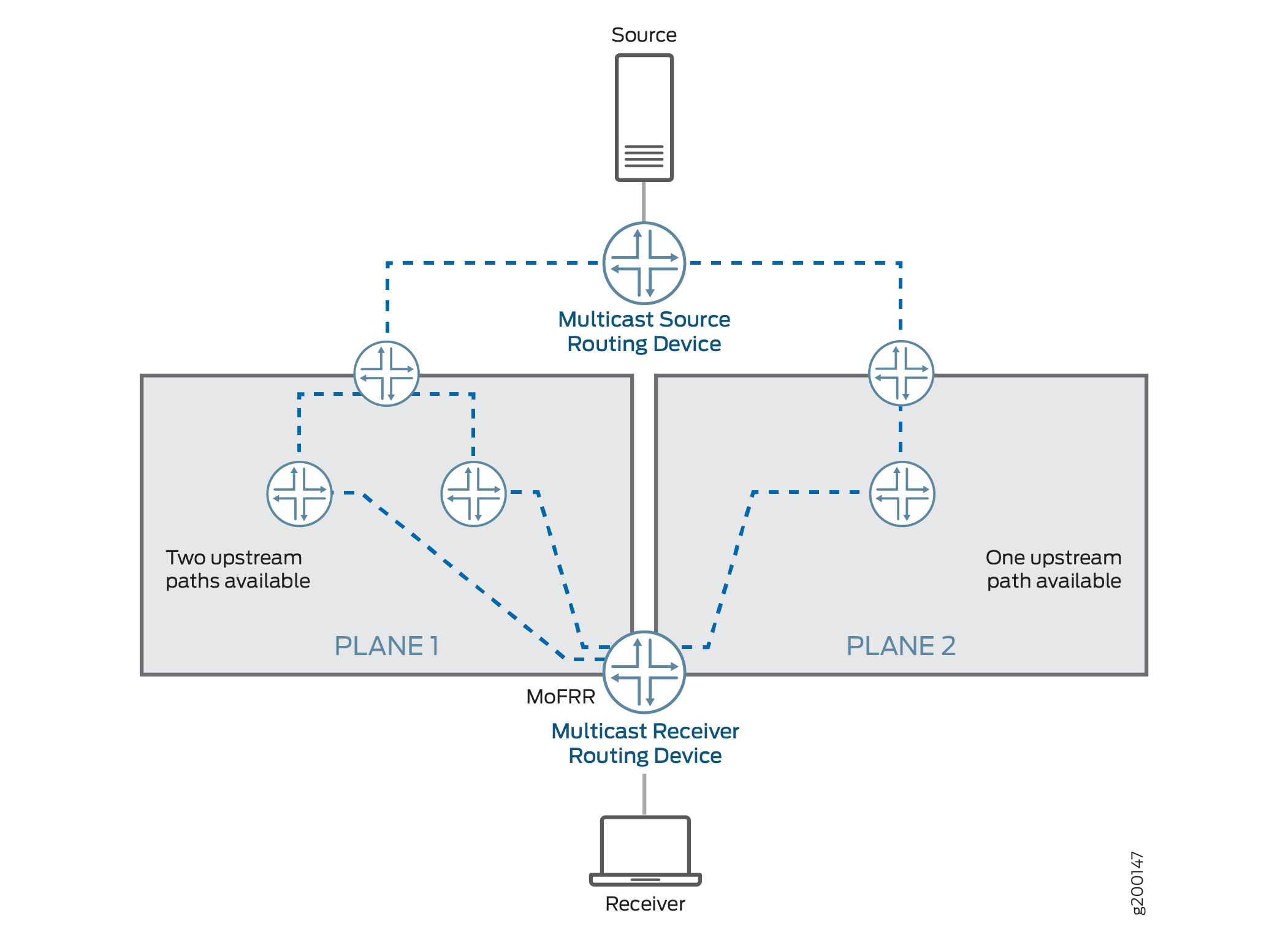
With MoFRR enabled, the egress (receiver side) routing device sets up two multicast trees, a primary path and a backup path, toward the multicast source for each (S,G). In other words, the egress routing device propagates the same (S,G) join messages toward two different upstream neighbors, thus creating two multicast trees.
One of the multicast trees goes through plane 1 and the other through plane 2, as shown in Figure 12. For each (S,G), the egress routing device forwards traffic received on the primary path and drops traffic received on the backup path.
MoFRR is supported on both equal-cost multipath (ECMP) paths
and non-ECMP paths. The device needs to enable unicast loop-free alternate
(LFA) routes to support MoFRR on non-ECMP paths. You enable LFA routes
using the link-protection statement in the interior gateway
protocol (IGP) configuration. When you enable link protection on an
OSPF or IS-IS interface, the device creates a backup LFA path to the
primary next hop for all destination routes that traverse the protected
interface.
Junos OS implements MoFRR in the IP network for IP MoFRR and at the MPLS label-edge routing device (LER) for multipoint LDP MoFRR.
Multipoint LDP MoFRR is used at the egress device of an MPLS network, where the packets are forwarded to an IP network. With multipoint LDP MoFRR, the device establishes two paths toward the upstream PE routing device for receiving two streams of MPLS packets at the LER. The device accepts one of the streams (the primary), and the other one (the backup) is dropped at the LER. IF the primary path fails, the device accepts the backup stream instead. Inband signaling support is a prerequisite for MoFRR with multipoint LDP (see Understanding Multipoint LDP Inband Signaling for Point-to-Multipoint LSPs).
PIM Functionality
Junos OS supports MoFRR for shortest-path tree (SPT) joins in
PIM source-specific multicast (SSM) and any-source multicast (ASM).
MoFRR is supported for both SSM and ASM ranges. To enable MoFRR for
(*,G) joins, include the mofrr-asm-starg configuration statement
at the [edit routing-options multicast stream-protection] hierarchy. For each group G, MoFRR will operate for either (S,G)
or (*,G), but not both. (S,G) always takes precedence over (*,G).
With MoFRR enabled, a PIM routing device propagates join messages on two upstream reverse-path forwarding (RPF) interfaces to receive multicast traffic on both links for the same join request. MoFRR gives preference to two paths that do not converge to the same immediate upstream routing device. PIM installs appropriate multicast routes with upstream RPF next hops with two interfaces (for the primary and backup paths).
When the primary path fails, the backup path is upgraded to primary status, and the device forwards traffic accordingly. If there are alternate paths available, MoFRR calculates a new backup path and updates or installs the appropriate multicast route.
You can enable MoFRR with PIM join load balancing (see the join-load-balance automatic statement). However, in that case the distribution
of join messages among the links might not be even. When a new ECMP
link is added, join messages on the primary path are redistributed
and load-balanced. The join messages on the backup path might still
follow the same path and might not be evenly redistributed.
You enable MoFRR using the stream-protection configuration
statement at the [edit routing-options multicast] hierarchy.
MoFRR is managed by a set of filter policies.
When an egress PIM routing device receives a join message or an IGMP report, it checks for an MoFRR configuration and proceeds as follows:
If the MoFRR configuration is not present, PIM sends a join message upstream toward one upstream neighbor (for example, plane 2 in Figure 12).
If the MoFRR configuration is present, the device checks for a policy configuration.
If a policy is not present, the device checks for primary and backup paths (upstream interfaces), and proceeds as follows:
If primary and backup paths are not available—PIM sends a join message upstream toward one upstream neighbor (for example, plane 2 in Figure 12).
If primary and backup paths are available—PIM sends the join message upstream toward two of the available upstream neighbors. Junos OS sets up primary and secondary multicast paths to receive multicast traffic (for example, plane 1 in Figure 12).
If a policy is present, the device checks whether the policy allows MoFRR for this (S,G), and proceeds as follows:
If this policy check fails—PIM sends a join message upstream toward one upstream neighbor (for example, plane 2 in Figure 12).
If this policy check passes—The device checks for primary and backup paths (upstream interfaces).
If the primary and backup paths are not available, PIM sends a join message upstream toward one upstream neighbor (for example, plane 2 in Figure 12).
If the primary and backup paths are available, PIM sends the join message upstream toward two of the available upstream neighbors. The device sets up primary and secondary multicast paths to receive multicast traffic (for example, plane 1 in Figure 12).
Multipoint LDP Functionality
To avoid MPLS traffic duplication, multipoint LDP usually selects only one upstream path. (See section 2.4.1.1. Determining One's 'upstream LSR' in RFC 6388, Label Distribution Protocol Extensions for Point-to-Multipoint and Multipoint-to-Multipoint Label Switched Paths.)
For multipoint LDP with MoFRR, the multipoint LDP device selects two separate upstream peers and sends two separate labels, one to each upstream peer. The device uses the same algorithm described in RFC 6388 to select the primary upstream path. The device uses the same algorithm to select the backup upstream path but excludes the primary upstream LSR as a candidate. The two different upstream peers send two streams of MPLS traffic to the egress routing device. The device selects only one of the upstream neighbor paths as the primary path from which to accept the MPLS traffic. The other path becomes the backup path, and the device drops that traffic. When the primary upstream path fails, the device starts accepting traffic from the backup path. The multipoint LDP device selects the two upstream paths based on the interior gateway protocol (IGP) root device next hop.
A forwarding equivalency class (FEC) is a group of IP packets that are forwarded in the same manner, over the same path, and with the same forwarding treatment. Normally, the label that is put on a particular packet represents the FEC to which that packet is assigned. In MoFRR, two routes are placed into the mpls.0 table for each FEC—one route for the primary label and the other route for the backup label.
If there are parallel links toward the same immediate upstream device, the device considers both parallel links to be the primary. At any point in time, the upstream device sends traffic on only one of the multiple parallel links.
A bud node is an LSR that is an egress LSR, but also has one or more directly connected downstream LSRs. For a bud node, the traffic from the primary upstream path is forwarded to a downstream LSR. If the primary upstream path fails, the MPLS traffic from the backup upstream path is forwarded to the downstream LSR. This means that the downstream LSR next hop is added to both MPLS routes along with the egress next hop.
As with PIM, you enable MoFRR with multipoint LDP using the stream-protection configuration statement at the [edit routing-options
multicast] hierarchy, and it’s managed by a set of filter
policies.
If you have enabled the multipoint LDP point-to-multipoint FEC for MoFRR, the device factors the following considerations into selecting the upstream path:
The targeted LDP sessions are skipped if there is a nontargeted LDP session. If there is a single targeted LDP session, the targeted LDP session is selected, but the corresponding point-to-multipoint FEC loses the MoFRR capability because there is no interface associated with the targeted LDP session.
All interfaces that belong to the same upstream LSR are considered to be the primary path.
For any root-node route updates, the upstream path is changed based on the latest next hops from the IGP. If a better path is available, multipoint LDP attempts to switch to the better path.
Packet Forwarding
For either PIM or multipoint LDP, the device performs multicast source stream selection at the ingress interface. This preserves fabric bandwidth and maximizes forwarding performance because it:
Avoids sending out duplicate streams across the fabric
Prevents multiple route lookups (that result in packet drops).
For PIM, each IP multicast stream contains the same destination address. Regardless of the interface on which the packets arrive, the packets have the same route. The device checks the interface upon which each packet arrives and forwards only those that are from the primary interface. If the interface matches a backup stream interface, the device drops the packets. If the interface doesn’t match either the primary or backup stream interface, the device handles the packets as exceptions in the control plane.
Figure 13 shows this process with sample primary and backup interfaces for routers with PIM. Figure 14 shows this similarly for switches with PIM.
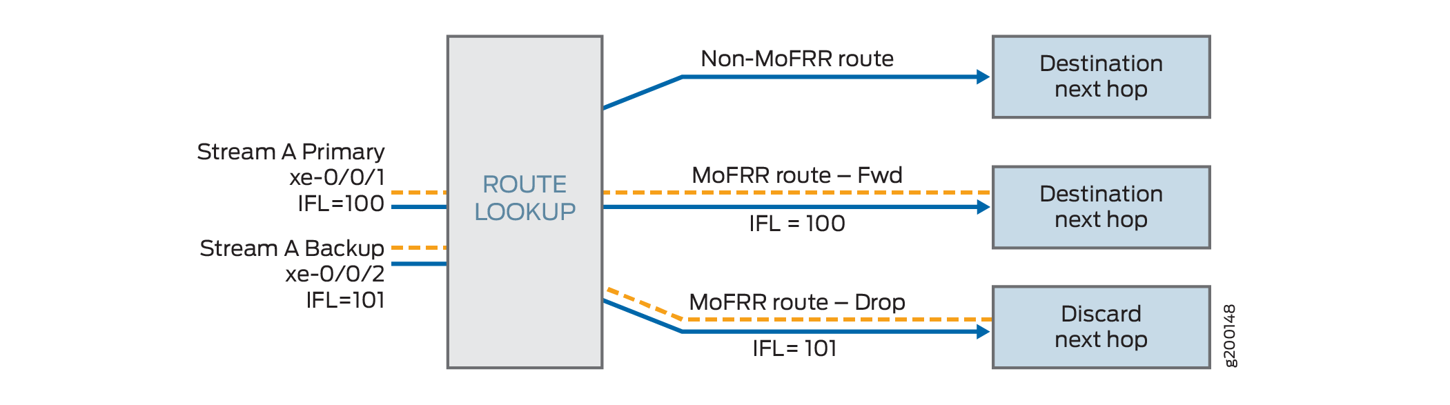
For MoFRR with multipoint LDP on routers, the device uses multiple MPLS labels to control MoFRR stream selection. Each label represents a separate route, but each references the same interface list check. The device only forwards the primary label, and drops all others. Multiple interfaces can receive packets using the same label.
Figure 15 shows this process for routers with multipoint LDP.
Limitations and Caveats
- MoFRR Limitations and Caveats on Switching and Routing Devices
- MoFRR Limitations on Switching Devices with PIM
- MoFRR Limitations and Caveats on Routing Devices with Multipoint LDP
MoFRR Limitations and Caveats on Switching and Routing Devices
MoFRR has the following limitations and caveats on routing and switching devices:
MoFRR failure detection is supported for immediate link protection of the routing device on which MoFRR is enabled and not on all the links (end-to-end) in the multicast traffic path.
MoFRR supports fast reroute on two selected disjoint paths toward the source. Two of the selected upstream neighbors cannot be on the same interface—in other words, two upstream neighbors on a LAN segment. The same is true if the upstream interface happens to be a multicast tunnel interface.
Detection of the maximum end-to-end disjoint upstream paths is not supported. The receiver side (egress) routing device only makes sure that there is a disjoint upstream device (the immediate previous hop). PIM and multipoint LDP do not support the equivalent of explicit route objects (EROs). Hence, disjoint upstream path detection is limited to control over the immediately previous hop device. Because of this limitation, the path to the upstream device of the previous hop selected as primary and backup might be shared.
You might see some traffic loss in the following scenarios:
A better upstream path becomes available on an egress device.
MoFRR is enabled or disabled on the egress device while there is an active traffic stream flowing.
PIM join load balancing for join messages for backup paths are not supported.
For a multicast group G, MoFRR is not allowed for both (S,G) and (*,G) join messages. (S,G) join messages have precedence over (*,G).
MoFRR is not supported for multicast traffic streams that use two different multicast groups. Each (S,G) combination is treated as a unique multicast traffic stream.
The bidirectional PIM range is not supported with MoFRR.
PIM dense-mode is not supported with MoFRR.
Multicast statistics for the backup traffic stream are not maintained by PIM and therefore are not available in the operational output of
showcommands.Rate monitoring is not supported.
MoFRR Limitations on Switching Devices with PIM
MoFRR with PIM has the following limitations on switching devices:
MoFRR is not supported when the upstream interface is an integrated routing and bridging (IRB) interface, which impacts other multicast features such as Internet Group Management Protocol version 3 (IGMPv3) snooping.
Packet replication and multicast lookups while forwarding multicast traffic can cause packets to recirculate through PFEs multiple times. As a result, displayed values for multicast packet counts from the
show pfe statistics trafficcommand might show higher numbers than expected in output fields such asInput packetsandOutput packets. You might notice this behavior more frequently in MoFRR scenarios because duplicate primary and backup streams increase the traffic flow in general.
MoFRR Limitations and Caveats on Routing Devices with Multipoint LDP
MoFRR has the following limitations and caveats on routers when used with multipoint LDP:
MoFRR does not apply to multipoint LDP traffic received on an RSVP tunnel because the RSVP tunnel is not associated with any interface.
Mixed upstream MoFRR is not supported. This refers to PIM multipoint LDP in-band signaling, wherein one upstream path is through multipoint LDP and the second upstream path is through PIM.
Multipoint LDP labels as inner labels are not supported.
If the source is reachable through multiple ingress (source-side) provider edge (PE) routing devices, multipoint LDP MoFRR is not supported.
Targeted LDP upstream sessions are not selected as the upstream device for MoFRR.
Multipoint LDP link protection on the backup path is not supported because there is no support for MoFRR inner labels.
Configuring Multicast-Only Fast Reroute
You can configure multicast-only fast reroute (MoFRR) to minimize packet loss in a network when there is a link failure.
When fast reroute is applied to unicast streams, an upstream router preestablishes MPLS label-switched paths (LSPs) or precomputes an IP loop-free alternate (LFA) fast reroute backup path to handle failure of a segment in the downstream path.
In multicast routing, the traffic distribution graphs are usually originated by the receiver. This is unlike unicast routing, which usually establishes the path from the source to the receiver. Protocols that are capable of establishing multicast distribution graphs are PIM (for IP), multipoint LDP (for MPLS) and RSVP-TE (for MPLS). Of these, PIM and multipoint LDP receivers initiate the distribution graph setup, and therefore:
The configuration steps are the same for enabling MoFRR for PIM on all devices that support this feature, unless otherwise indicated. Configuration steps that are not applicable to multipoint LDP MoFRR are also indicated.
Platform-Specific MoFRR Behavior
Use Feature Explorer to confirm platform and release support for specific features.
Use the following table to review platform-specific behavior for your platform.
|
Platform |
Difference |
|---|---|
|
QFX Series and PTX Series |
|
|
MX Series and SRX Series |
|
To configure MoFRR on routers or switches:
Example: Configuring Multicast-Only Fast Reroute in a Multipoint LDP Domain
This example shows how to configure multicast-only fast reroute (MoFRR) to minimize packet loss in a network when there is a link failure.
Multipoint LDP MoFRR is used at the egress node of an MPLS network, where the packets are forwarded to an IP network. In the case of multipoint LDP MoFRR, the two paths toward the upstream provider edge (PE) router are established for receiving two streams of MPLS packets at the label-edge router (LER). One of the streams (the primary) is accepted, and the other one (the backup) is dropped at the LER. The backup stream is accepted if the primary path fails.
Requirements
No special configuration beyond device initialization is required before configuring this example.
In a multipoint LDP domain, for MoFRR to work, only the egress PE router needs to have MoFRR enabled. The other routers do not need to support MoFRR.
MoFRR is supported on MX Series platforms with MPC line cards.
As a prerequisite, the router must be set to network-services enhanced-ip mode, and all the line-cards in the platform must
be MPCs.
This example requires Junos OS Release 14.1 or later on the egress PE router.
Overview
In this example, Device R3 is the egress edge router. MoFRR is enabled on this device only.
OSPF is used for connectivity, though any interior gateway protocol (IGP) or static routes can be used.
For testing purposes, routers are used to simulate the source
and the receiver. Device R4 and Device R8 are configured to statically
join the desired group by using the set protocols igmp interface
interface-name static group group command.
In the case when a real multicast receiver host is not available,
as in this example, this static IGMP configuration is useful. On the
receivers, to make them listen to the multicast group address, this
example uses set protocols sap listen group.
MoFRR configuration includes a policy option that is not shown in this example, but is explained separately. The option is configured as follows:
stream-protection { policy policy-name; }
Topology
Figure 16 shows the sample network.
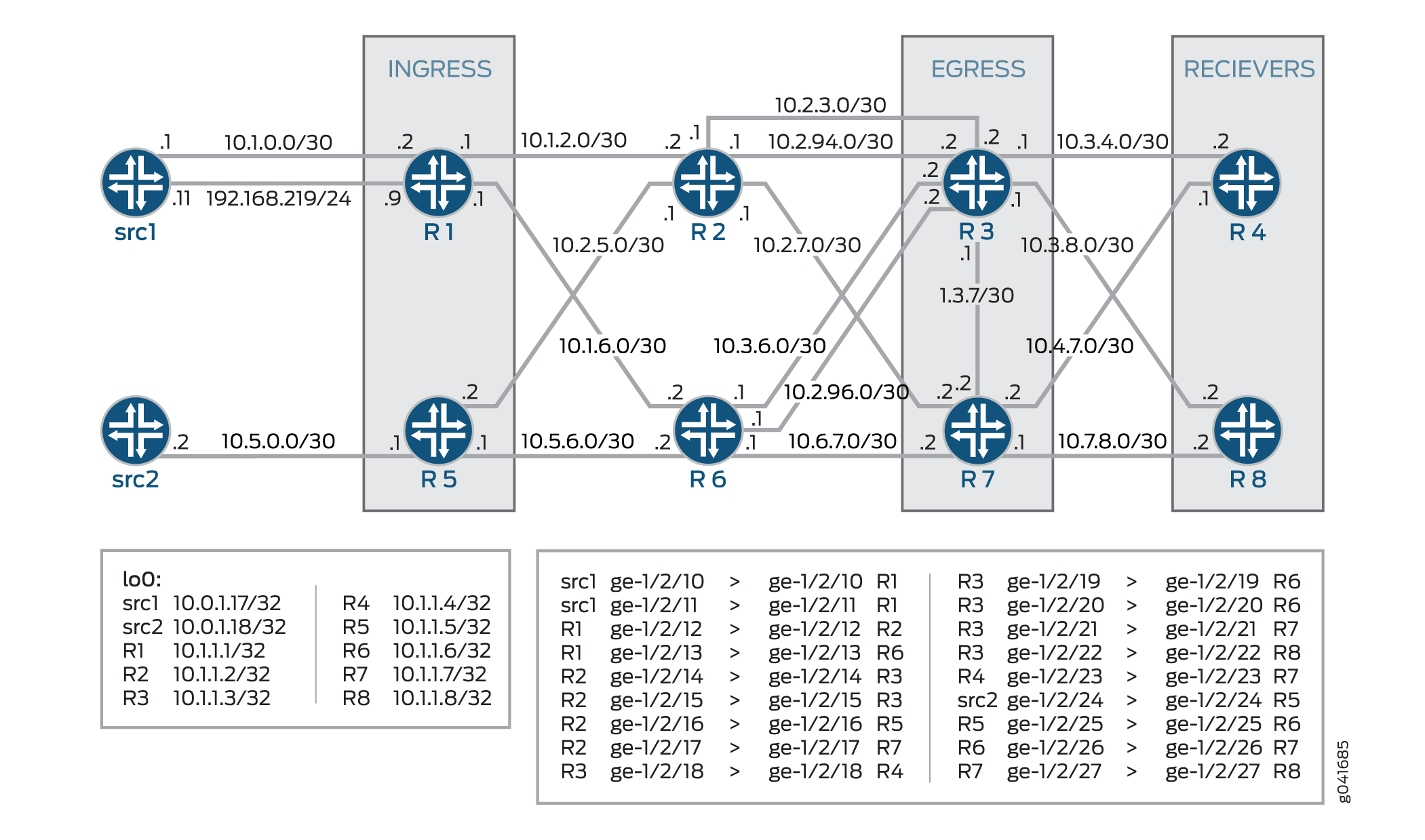
CLI Quick Configuration shows the configuration for all of the devices in Figure 16.
The section Configuration describes the steps on Device R3.
CLI Quick Configuration
CLI Quick Configuration
To quickly configure this example, copy the
following commands, paste them into a text file, remove any line breaks,
change any details necessary to match your network configuration,
and then copy and paste the commands into the CLI at the [edit] hierarchy level.
Device src1
set interfaces ge-1/2/10 unit 0 description src1-to-R1 set interfaces ge-1/2/10 unit 0 family inet address 10.5.0.1/30 set interfaces ge-1/2/11 unit 0 description src1-to-R1 set interfaces ge-1/2/11 unit 0 family inet address 192.168.219.11/24 set interfaces lo0 unit 0 family inet address 10.0.1.17/32 set protocols ospf area 0.0.0.0 interface all set protocols ospf area 0.0.0.0 interface lo0.0 passive
Device src2
set interfaces ge-1/2/24 unit 0 description src2-to-R5 set interfaces ge-1/2/24 unit 0 family inet address 10.5.0.2/30 set interfaces lo0 unit 0 family inet address 10.0.1.18/32 set protocols rsvp interface all set protocols ospf area 0.0.0.0 interface all set protocols ospf area 0.0.0.0 interface lo0.0 passive
Device R1
set interfaces ge-1/2/12 unit 0 description R1-to-R2 set interfaces ge-1/2/12 unit 0 family inet address 10.1.2.1/30 set interfaces ge-1/2/12 unit 0 family mpls set interfaces ge-1/2/13 unit 0 description R1-to-R6 set interfaces ge-1/2/13 unit 0 family inet address 10.1.6.1/30 set interfaces ge-1/2/13 unit 0 family mpls set interfaces ge-1/2/10 unit 0 description R1-to-src1 set interfaces ge-1/2/10 unit 0 family inet address 10.1.0.2/30 set interfaces ge-1/2/11 unit 0 description R1-to-src1 set interfaces ge-1/2/11 unit 0 family inet address 192.168.219.9/30 set interfaces lo0 unit 0 family inet address 10.1.1.1/32 set protocols rsvp interface all set protocols mpls interface all set protocols bgp group ibgp local-address 10.1.1.1 set protocols bgp group ibgp export static-route-tobgp set protocols bgp group ibgp peer-as 65010 set protocols bgp group ibgp neighbor 10.1.1.3 set protocols bgp group ibgp neighbor 10.1.1.7 set protocols ospf traffic-engineering set protocols ospf area 0.0.0.0 interface all set protocols ospf area 0.0.0.0 interface lo0.0 passive set protocols ldp interface ge-1/2/12.0 set protocols ldp interface ge-1/2/13.0 set protocols ldp interface lo0.0 set protocols ldp p2mp set protocols pim mldp-inband-signalling policy mldppim-ex set protocols pim rp static address 10.1.1.5 set protocols pim interface lo0.0 set protocols pim interface ge-1/2/10.0 set protocols pim interface ge-1/2/11.0 set policy-options policy-statement mldppim-ex term B from source-address-filter 192.168.0.0/24 orlonger set policy-options policy-statement mldppim-ex term B from source-address-filter 192.168.219.11/32 orlonger set policy-options policy-statement mldppim-ex term B then p2mp-lsp-root address 10.1.1.2 set policy-options policy-statement mldppim-ex term B then accept set policy-options policy-statement mldppim-ex term A from source-address-filter 10.1.1.7/32 orlonger set policy-options policy-statement mldppim-ex term A from source-address-filter 10.1.0.0/30 orlonger set policy-options policy-statement mldppim-ex term A then accept set policy-options policy-statement static-route-tobgp term static from protocol static set policy-options policy-statement static-route-tobgp term static from protocol direct set policy-options policy-statement static-route-tobgp term static then accept set routing-options autonomous-system 65010
Device R2
set interfaces ge-1/2/12 unit 0 description R2-to-R1 set interfaces ge-1/2/12 unit 0 family inet address 10.1.2.2/30 set interfaces ge-1/2/12 unit 0 family mpls set interfaces ge-1/2/14 unit 0 description R2-to-R3 set interfaces ge-1/2/14 unit 0 family inet address 10.2.3.1/30 set interfaces ge-1/2/14 unit 0 family mpls set interfaces ge-1/2/16 unit 0 description R2-to-R5 set interfaces ge-1/2/16 unit 0 family inet address 10.2.5.1/30 set interfaces ge-1/2/16 unit 0 family mpls set interfaces ge-1/2/17 unit 0 description R2-to-R7 set interfaces ge-1/2/17 unit 0 family inet address 10.2.7.1/30 set interfaces ge-1/2/17 unit 0 family mpls set interfaces ge-1/2/15 unit 0 description R2-to-R3 set interfaces ge-1/2/15 unit 0 family inet address 10.2.94.1/30 set interfaces ge-1/2/15 unit 0 family mpls set interfaces lo0 unit 0 family inet address 10.1.1.2/32 set interfaces lo0 unit 0 family mpls set protocols rsvp interface all set protocols mpls interface all set protocols ospf traffic-engineering set protocols ospf area 0.0.0.0 interface all set protocols ospf area 0.0.0.0 interface lo0.0 passive set protocols ldp interface all set protocols ldp p2mp set policy-options policy-statement mldppim-ex term B from source-address-filter 192.168.0.0/24 orlonger set policy-options policy-statement mldppim-ex term B from source-address-filter 192.168.219.11/32 orlonger set policy-options policy-statement mldppim-ex term B then p2mp-lsp-root address 10.1.1.2 set policy-options policy-statement mldppim-ex term B then accept set routing-options autonomous-system 65010
Device R3
set chassis network-services enhanced-ip set interfaces ge-1/2/14 unit 0 description R3-to-R2 set interfaces ge-1/2/14 unit 0 family inet address 10.2.3.2/30 set interfaces ge-1/2/14 unit 0 family mpls set interfaces ge-1/2/18 unit 0 description R3-to-R4 set interfaces ge-1/2/18 unit 0 family inet address 10.3.4.1/30 set interfaces ge-1/2/18 unit 0 family mpls set interfaces ge-1/2/19 unit 0 description R3-to-R6 set interfaces ge-1/2/19 unit 0 family inet address 10.3.6.2/30 set interfaces ge-1/2/19 unit 0 family mpls set interfaces ge-1/2/21 unit 0 description R3-to-R7 set interfaces ge-1/2/21 unit 0 family inet address 10.3.7.1/30 set interfaces ge-1/2/21 unit 0 family mpls set interfaces ge-1/2/22 unit 0 description R3-to-R8 set interfaces ge-1/2/22 unit 0 family inet address 10.3.8.1/30 set interfaces ge-1/2/22 unit 0 family mpls set interfaces ge-1/2/15 unit 0 description R3-to-R2 set interfaces ge-1/2/15 unit 0 family inet address 10.2.94.2/30 set interfaces ge-1/2/15 unit 0 family mpls set interfaces ge-1/2/20 unit 0 description R3-to-R6 set interfaces ge-1/2/20 unit 0 family inet address 10.2.96.2/30 set interfaces ge-1/2/20 unit 0 family mpls set interfaces lo0 unit 0 family inet address 10.1.1.3/32 primary set routing-options autonomous-system 65010 set routing-options multicast stream-protection set protocols rsvp interface all set protocols mpls interface all set protocols bgp group ibgp local-address 10.1.1.3 set protocols bgp group ibgp peer-as 10 set protocols bgp group ibgp neighbor 10.1.1.1 set protocols bgp group ibgp neighbor 10.1.1.5 set protocols ospf traffic-engineering set protocols ospf area 0.0.0.0 interface all set protocols ospf area 0.0.0.0 interface fxp0.0 disable set protocols ospf area 0.0.0.0 interface lo0.0 passive set protocols ldp interface all set protocols ldp p2mp set protocols pim mldp-inband-signalling policy mldppim-ex set protocols pim interface lo0.0 set protocols pim interface ge-1/2/18.0 set protocols pim interface ge-1/2/22.0 set policy-options policy-statement mldppim-ex term B from source-address-filter 192.168.0.0/24 orlonger set policy-options policy-statement mldppim-ex term B from source-address-filter 192.168.219.11/32 orlonger set policy-options policy-statement mldppim-ex term B then accept set policy-options policy-statement mldppim-ex term A from source-address-filter 10.1.0.1/30 orlonger set policy-options policy-statement mldppim-ex term A then accept set policy-options policy-statement static-route-tobgp term static from protocol static set policy-options policy-statement static-route-tobgp term static from protocol direct set policy-options policy-statement static-route-tobgp term static then accept
Device R4
set interfaces ge-1/2/18 unit 0 description R4-to-R3 set interfaces ge-1/2/18 unit 0 family inet address 10.3.4.2/30 set interfaces ge-1/2/18 unit 0 family mpls set interfaces ge-1/2/23 unit 0 description R4-to-R7 set interfaces ge-1/2/23 unit 0 family inet address 10.4.7.1/30 set interfaces lo0 unit 0 family inet address 10.1.1.4/32 set protocols igmp interface ge-1/2/18.0 version 3 set protocols igmp interface ge-1/2/18.0 static group 232.1.1.1 group-count 2 set protocols igmp interface ge-1/2/18.0 static group 232.1.1.1 source 192.168.219.11 set protocols igmp interface ge-1/2/18.0 static group 232.2.2.2 source 10.2.7.7 set protocols sap listen 232.1.1.1 set protocols sap listen 232.2.2.2 set protocols rsvp interface all set protocols mpls interface all set protocols ospf traffic-engineering set protocols ospf area 0.0.0.0 interface all set protocols ospf area 0.0.0.0 interface lo0.0 passive set protocols pim mldp-inband-signalling policy mldppim-ex set protocols pim interface ge-1/2/23.0 set protocols pim interface ge-1/2/18.0 set protocols pim interface lo0.0 set policy-options policy-statement static-route-tobgp term static from protocol static set policy-options policy-statement static-route-tobgp term static from protocol direct set policy-options policy-statement static-route-tobgp term static then accept set policy-options policy-statement mldppim-ex term B from source-address-filter 192.168.0.0/24 orlonger set policy-options policy-statement mldppim-ex term B from source-address-filter 192.168.219.11/32 orlonger set policy-options policy-statement mldppim-ex term B then p2mp-lsp-root address 10.1.1.2 set policy-options policy-statement mldppim-ex term B then accept set routing-options autonomous-system 65010
Device R5
set interfaces ge-1/2/24 unit 0 description R5-to-src2 set interfaces ge-1/2/24 unit 0 family inet address 10.5.0.1/30 set interfaces ge-1/2/16 unit 0 description R5-to-R2 set interfaces ge-1/2/16 unit 0 family inet address 10.2.5.2/30 set interfaces ge-1/2/16 unit 0 family mpls set interfaces ge-1/2/25 unit 0 description R5-to-R6 set interfaces ge-1/2/25 unit 0 family inet address 10.5.6.1/30 set interfaces ge-1/2/25 unit 0 family mpls set interfaces lo0 unit 0 family inet address 10.1.1.5/32 set protocols rsvp interface all set protocols mpls interface all set protocols bgp group ibgp local-address 10.1.1.5 set protocols bgp group ibgp export static-route-tobgp set protocols bgp group ibgp peer-as 65010 set protocols bgp group ibgp neighbor 10.1.1.7 set protocols bgp group ibgp neighbor 10.1.1.3 set protocols ospf traffic-engineering set protocols ospf area 0.0.0.0 interface all set protocols ospf area 0.0.0.0 interface lo0.0 passive set protocols ldp interface ge-1/2/16.0 set protocols ldp interface ge-1/2/25.0 set protocols ldp p2mp set protocols pim interface lo0.0 set protocols pim interface ge-1/2/24.0 set policy-options policy-statement static-route-tobgp term static from protocol static set policy-options policy-statement static-route-tobgp term static from protocol direct set policy-options policy-statement static-route-tobgp term static then accept set routing-options autonomous-system 65010
Device R6
set interfaces ge-1/2/13 unit 0 description R6-to-R1 set interfaces ge-1/2/13 unit 0 family inet address 10.1.6.2/30 set interfaces ge-1/2/13 unit 0 family mpls set interfaces ge-1/2/19 unit 0 description R6-to-R3 set interfaces ge-1/2/19 unit 0 family inet address 10.3.6.1/30 set interfaces ge-1/2/19 unit 0 family mpls set interfaces ge-1/2/25 unit 0 description R6-to-R5 set interfaces ge-1/2/25 unit 0 family inet address 10.5.6.2/30 set interfaces ge-1/2/25 unit 0 family mpls set interfaces ge-1/2/26 unit 0 description R6-to-R7 set interfaces ge-1/2/26 unit 0 family inet address 10.6.7.1/30 set interfaces ge-1/2/26 unit 0 family mpls set interfaces ge-1/2/20 unit 0 description R6-to-R3 set interfaces ge-1/2/20 unit 0 family inet address 10.2.96.1/30 set interfaces ge-1/2/20 unit 0 family mpls set interfaces lo0 unit 0 family inet address 10.1.1.6/30 set protocols rsvp interface all set protocols mpls interface all set protocols ospf traffic-engineering set protocols ospf area 0.0.0.0 interface all set protocols ospf area 0.0.0.0 interface lo0.0 passive set protocols ldp interface all set protocols ldp p2mp
Device R7
set interfaces ge-1/2/17 unit 0 description R7-to-R2 set interfaces ge-1/2/17 unit 0 family inet address 10.2.7.2/30 set interfaces ge-1/2/17 unit 0 family mpls set interfaces ge-1/2/21 unit 0 description R7-to-R3 set interfaces ge-1/2/21 unit 0 family inet address 10.3.7.2/30 set interfaces ge-1/2/21 unit 0 family mpls set interfaces ge-1/2/23 unit 0 description R7-to-R4 set interfaces ge-1/2/23 unit 0 family inet address 10.4.7.2/30 set interfaces ge-1/2/23 unit 0 family mpls set interfaces ge-1/2/26 unit 0 description R7-to-R6 set interfaces ge-1/2/26 unit 0 family inet address 10.6.7.2/30 set interfaces ge-1/2/26 unit 0 family mpls set interfaces ge-1/2/27 unit 0 description R7-to-R8 set interfaces ge-1/2/27 unit 0 family inet address 10.7.8.1/30 set interfaces ge-1/2/27 unit 0 family mpls set interfaces lo0 unit 0 family inet address 10.1.1.7/32 set protocols rsvp interface all set protocols mpls interface all set protocols bgp group ibgp local-address 10.1.1.7 set protocols bgp group ibgp export static-route-tobgp set protocols bgp group ibgp peer-as 65010 set protocols bgp group ibgp neighbor 10.1.1.5 set protocols bgp group ibgp neighbor 10.1.1.1 set protocols ospf traffic-engineering set protocols ospf area 0.0.0.0 interface all set protocols ospf area 0.0.0.0 interface lo0.0 passive set protocols ldp interface ge-1/2/17.0 set protocols ldp interface ge-1/2/21.0 set protocols ldp interface ge-1/2/26.0 set protocols ldp p2mp set protocols pim mldp-inband-signalling policy mldppim-ex set protocols pim interface lo0.0 set protocols pim interface ge-1/2/27.0 set policy-options policy-statement mldppim-ex term B from source-address-filter 192.168.0.0/24 orlonger set policy-options policy-statement mldppim-ex term B from source-address-filter 192.168.219.11/32 orlonger set policy-options policy-statement mldppim-ex term B then accept set policy-options policy-statement mldppim-ex term A from source-address-filter 10.1.0.1/30 orlonger set policy-options policy-statement mldppim-ex term A then accept set policy-options policy-statement static-route-tobgp term static from protocol static set policy-options policy-statement static-route-tobgp term static from protocol direct set policy-options policy-statement static-route-tobgp term static then accept set routing-options autonomous-system 65010 set routing-options multicast stream-protection policy mldppim-ex
Device R8
set interfaces ge-1/2/22 unit 0 description R8-to-R3 set interfaces ge-1/2/22 unit 0 family inet address 10.3.8.2/30 set interfaces ge-1/2/22 unit 0 family mpls set interfaces ge-1/2/27 unit 0 description R8-to-R7 set interfaces ge-1/2/27 unit 0 family inet address 10.7.8.2/30 set interfaces ge-1/2/27 unit 0 family mpls set interfaces lo0 unit 0 family inet address 10.1.1.8/32 set protocols igmp interface ge-1/2/22.0 version 3 set protocols igmp interface ge-1/2/22.0 static group 232.1.1.1 group-count 2 set protocols igmp interface ge-1/2/22.0 static group 232.1.1.1 source 192.168.219.11 set protocols igmp interface ge-1/2/22.0 static group 232.2.2.2 source 10.2.7.7 set protocols sap listen 232.1.1.1 set protocols sap listen 232.2.2.2 set protocols rsvp interface all set protocols ospf traffic-engineering set protocols ospf area 0.0.0.0 interface all set protocols ospf area 0.0.0.0 interface lo0.0 passive set protocols pim mldp-inband-signalling policy mldppim-ex set protocols pim interface ge-1/2/27.0 set protocols pim interface ge-1/2/22.0 set protocols pim interface lo0.0 set policy-options policy-statement static-route-tobgp term static from protocol static set policy-options policy-statement static-route-tobgp term static from protocol direct set policy-options policy-statement static-route-tobgp term static then accept set policy-options policy-statement mldppim-ex term B from source-address-filter 192.168.0.0/24 orlonger set policy-options policy-statement mldppim-ex term B from source-address-filter 192.168.219.11/32 orlonger set policy-options policy-statement mldppim-ex term B then p2mp-lsp-root address 10.1.1.2 set policy-options policy-statement mldppim-ex term B then accept set routing-options autonomous-system 65010
Configuration
Procedure
Step-by-Step Procedure
The following example requires that you navigate various levels in the configuration hierarchy. For information about navigating the CLI, see Using the CLI Editor in Configuration Mode in the Junos OS CLI User Guide.
To configure Device R3:
Enable enhanced IP mode.
[edit chassis] user@R3# set network-services enhanced-ip
Configure the device interfaces.
[edit interfaces] user@R3# set ge-1/2/14 unit 0 description R3-to-R2 user@R3# set ge-1/2/14 unit 0 family inet address 10.2.3.2/30 user@R3# set ge-1/2/14 unit 0 family mpls user@R3# set ge-1/2/18 unit 0 description R3-to-R4 user@R3# set ge-1/2/18 unit 0 family inet address 10.3.4.1/30 user@R3# set ge-1/2/18 unit 0 family mpls user@R3# set ge-1/2/19 unit 0 description R3-to-R6 user@R3# set ge-1/2/19 unit 0 family inet address 10.3.6.2/30 user@R3# set ge-1/2/19 unit 0 family mpls user@R3# set ge-1/2/21 unit 0 description R3-to-R7 user@R3# set ge-1/2/21 unit 0 family inet address 10.3.7.1/30 user@R3# set ge-1/2/21 unit 0 family mpls user@R3# set ge-1/2/22 unit 0 description R3-to-R8 user@R3# set ge-1/2/22 unit 0 family inet address 10.3.8.1/30 user@R3# set ge-1/2/22 unit 0 family mpls user@R3# set ge-1/2/15 unit 0 description R3-to-R2 user@R3# set ge-1/2/15 unit 0 family inet address 10.2.94.2/30 user@R3# set ge-1/2/15 unit 0 family mpls user@R3# set ge-1/2/20 unit 0 description R3-to-R6 user@R3# set ge-1/2/20 unit 0 family inet address 10.2.96.2/30 user@R3# set ge-1/2/20 unit 0 family mpls user@R3# set lo0 unit 0 family inet address 10.1.1.3/32 primary
Configure the autonomous system (AS) number.
user@R3# set routing-options autonomous-system 6510
Configure the routing policies.
[edit policy-options policy-statement mldppim-ex] user@R3# set term B from source-address-filter 192.168.0.0/24 orlonger user@R3# set term B from source-address-filter 192.168.219.11/32 orlonger user@R3# set term B then accept user@R3# set term A from source-address-filter 10.1.0.1/30 orlonger user@R3# set term A then accept [edit policy-options policy-statement static-route-tobgp] user@R3# set term static from protocol static user@R3# set term static from protocol direct user@R3# set term static then accept
Configure PIM.
[edit protocols pim] user@R3# set mldp-inband-signalling policy mldppim-ex user@R3# set interface lo0.0 user@R3# set interface ge-1/2/18.0 user@R3# set interface ge-1/2/22.0
Configure LDP.
[edit protocols ldp] user@R3# set interface all user@R3# set p2mp
Configure an IGP or static routes.
[edit protocols ospf] user@R3# set traffic-engineering user@R3# set area 0.0.0.0 interface all user@R3# set area 0.0.0.0 interface fxp0.0 disable user@R3# set area 0.0.0.0 interface lo0.0 passive
Configure internal BGP.
[edit protocols bgp group ibgp] user@R3# set local-address 10.1.1.3 user@R3# set peer-as 65010 user@R3# set neighbor 10.1.1.1 user@R3# set neighbor 10.1.1.5
Configure MPLS and, optionally, RSVP.
[edit protocols mpls] user@R3# set interface all [edit protocols rsvp] user@R3# set interface all
Enable MoFRR.
[edit routing-options multicast] user@R3# set stream-protection
Results
From configuration mode, confirm your configuration
by entering the show chassis, show interfaces, show protocols, show policy-options, and show routing-options commands. If the output does not display
the intended configuration, repeat the instructions in this example
to correct the configuration.
user@R3# show chassis network-services enhanced-ip;
user@R3# show interfaces
ge-1/2/14 {
unit 0 {
description R3-to-R2;
family inet {
address 10.2.3.2/30;
}
family mpls;
}
}
ge-1/2/18 {
unit 0 {
description R3-to-R4;
family inet {
address 10.3.4.1/30;
}
family mpls;
}
}
ge-1/2/19 {
unit 0 {
description R3-to-R6;
family inet {
address 10.3.6.2/30;
}
family mpls;
}
}
ge-1/2/21 {
unit 0 {
description R3-to-R7;
family inet {
address 10.3.7.1/30;
}
family mpls;
}
}
ge-1/2/22 {
unit 0 {
description R3-to-R8;
family inet {
address 10.3.8.1/30;
}
family mpls;
}
}
ge-1/2/15 {
unit 0 {
description R3-to-R2;
family inet {
address 10.2.94.2/30;
}
family mpls;
}
}
ge-1/2/20 {
unit 0 {
description R3-to-R6;
family inet {
address 10.2.96.2/30;
}
family mpls;
}
}
lo0 {
unit 0 {
family inet {
address 192.168.15.1/32;
address 10.1.1.3/32 {
primary;
}
}
}
}
user@R3# show protocols
rsvp {
interface all;
}
mpls {
interface all;
}
bgp {
group ibgp {
local-address 10.1.1.3;
peer-as 65010;
neighbor 10.1.1.1;
neighbor 10.1.1.5;
}
}
ospf {
traffic-engineering;
area 0.0.0.0 {
interface all;
interface fxp0.0 {
disable;
}
interface lo0.0 {
passive;
}
}
}
ldp {
interface all;
p2mp;
}
pim {
mldp-inband-signalling {
policy mldppim-ex;
}
interface lo0.0;
interface ge-1/2/18.0;
interface ge-1/2/22.0;
}
user@R3# show policy-options
policy-statement mldppim-ex {
term B {
from {
source-address-filter 192.168.0.0/24 orlonger;
source-address-filter 192.168.219.11/32 orlonger;
}
then accept;
}
term A {
from {
source-address-filter 10.1.0.1/30 orlonger;
}
then accept;
}
}
policy-statement static-route-tobgp {
term static {
from protocol [ static direct ];
then accept;
}
}
user@R3# show routing-options
autonomous-system 65010;
multicast {
stream-protection;
}
If you are done configuring the device, enter commit from configuration mode.
Verification
Confirm that the configuration is working properly.
- Checking the LDP Point-to-Multipoint Forwarding Equivalency Classes
- Examining the Label Information
- Checking the Multicast Routes
- Checking the LDP Point-to-Multipoint Traffic Statistics
Checking the LDP Point-to-Multipoint Forwarding Equivalency Classes
Purpose
Make sure the MoFRR is enabled, and determine what labels are being used.
Action
user@R3> show ldp p2mp fec LDP P2MP FECs: P2MP root-addr 10.1.1.1, grp: 232.1.1.1, src: 192.168.219.11 MoFRR enabled Fec type: Egress (Active) Label: 301568 P2MP root-addr 10.1.1.1, grp: 232.1.1.2, src: 192.168.219.11 MoFRR enabled Fec type: Egress (Active) Label: 301600
Meaning
The output shows that MoFRR is enabled, and it shows that the labels 301568 and 301600 are being used for the two multipoint LDP point-to-multipoint LSPs.
Examining the Label Information
Purpose
Make sure that the egress device has two upstream interfaces for the multicast group join.
Action
user@R3> show route label 301568 detail
mpls.0: 18 destinations, 18 routes (18 active, 0 holddown, 0 hidden)
301568 (1 entry, 1 announced)
*LDP Preference: 9
Next hop type: Flood
Address: 0x2735208
Next-hop reference count: 3
Next hop type: Router, Next hop index: 1397
Address: 0x2735d2c
Next-hop reference count: 3
Next hop: 10.3.8.2 via ge-1/2/22.0
Label operation: Pop
Load balance label: None;
Next hop type: Router, Next hop index: 1395
Address: 0x2736290
Next-hop reference count: 3
Next hop: 10.3.4.2 via ge-1/2/18.0
Label operation: Pop
Load balance label: None;
State: <Active Int AckRequest MulticastRPF>
Local AS: 65010
Age: 54:05 Metric: 1
Validation State: unverified
Task: LDP
Announcement bits (1): 0-KRT
AS path: I
FECs bound to route: P2MP root-addr 10.1.1.1, grp: 232.1.1.1, src: 192.168.219.11
Primary Upstream : 10.1.1.3:0--10.1.1.2:0
RPF Nexthops :
ge-1/2/15.0, 10.2.94.1, Label: 301568, weight: 0x1
ge-1/2/14.0, 10.2.3.1, Label: 301568, weight: 0x1
Backup Upstream : 10.1.1.3:0--10.1.1.6:0
RPF Nexthops :
ge-1/2/20.0, 10.2.96.1, Label: 301584, weight: 0xfffe
ge-1/2/19.0, 10.3.6.1, Label: 301584, weight: 0xfffe
user@R3> show route label 301600 detail
mpls.0: 18 destinations, 18 routes (18 active, 0 holddown, 0 hidden)
301600 (1 entry, 1 announced)
*LDP Preference: 9
Next hop type: Flood
Address: 0x27356b4
Next-hop reference count: 3
Next hop type: Router, Next hop index: 1520
Address: 0x27350f4
Next-hop reference count: 3
Next hop: 10.3.8.2 via ge-1/2/22.0
Label operation: Pop
Load balance label: None;
Next hop type: Router, Next hop index: 1481
Address: 0x273645c
Next-hop reference count: 3
Next hop: 10.3.4.2 via ge-1/2/18.0
Label operation: Pop
Load balance label: None;
State: <Active Int AckRequest MulticastRPF>
Local AS: 65010
Age: 54:25 Metric: 1
Validation State: unverified
Task: LDP
Announcement bits (1): 0-KRT
AS path: I
FECs bound to route: P2MP root-addr 10.1.1.1, grp: 232.1.1.2, src: 192.168.219.11
Primary Upstream : 10.1.1.3:0--10.1.1.6:0
RPF Nexthops :
ge-1/2/20.0, 10.2.96.1, Label: 301600, weight: 0x1
ge-1/2/19.0, 10.3.6.1, Label: 301600, weight: 0x1
Backup Upstream : 10.1.1.3:0--1.1.1.2:0
RPF Nexthops :
ge-1/2/15.0, 10.2.94.1, Label: 301616, weight: 0xfffe
ge-1/2/14.0, 10.2.3.1, Label: 301616, weight: 0xfffeMeaning
The output shows the primary upstream paths and the backup upstream paths. It also shows the RPF next hops.
Checking the Multicast Routes
Purpose
Examine the IP multicast forwarding table to make sure that there is an upstream RPF interface list, with a primary and a backup interface.
Action
user@R3> show ldp p2mp path
P2MP path type: Transit/Egress
Output Session (label): 10.1.1.2:0 (301568) (Primary)
Egress Nexthops: Interface ge-1/2/18.0
Interface ge-1/2/22.0
RPF Nexthops: Interface ge-1/2/15.0, 10.2.94.1, 301568, 1
Interface ge-1/2/20.0, 10.2.96.1, 301584, 65534
Interface ge-1/2/14.0, 10.2.3.1, 301568, 1
Interface ge-1/2/19.0, 10.3.6.1, 301584, 65534
Attached FECs: P2MP root-addr 10.1.1.1, grp: 232.1.1.1, src: 192.168.219.11 (Active)
P2MP path type: Transit/Egress
Output Session (label): 10.1.1.6:0 (301584) (Backup)
Egress Nexthops: Interface ge-1/2/18.0
Interface ge-1/2/22.0
RPF Nexthops: Interface ge-1/2/15.0, 10.2.94.1, 301568, 1
Interface ge-1/2/20.0, 10.2.96.1, 301584, 65534
Interface ge-1/2/14.0, 10.2.3.1, 301568, 1
Interface ge-1/2/19.0, 10.3.6.1, 301584, 65534
Attached FECs: P2MP root-addr 10.1.1.1, grp: 232.1.1.1, src: 192.168.219.11 (Active)
P2MP path type: Transit/Egress
Output Session (label): 10.1.1.6:0 (301600) (Primary)
Egress Nexthops: Interface ge-1/2/18.0
Interface ge-1/2/22.0
RPF Nexthops: Interface ge-1/2/15.0, 10.2.94.1, 301616, 65534
Interface ge-1/2/20.0, 10.2.96.1, 301600, 1
Interface ge-1/2/14.0, 10.2.3.1, 301616, 65534
Interface ge-1/2/19.0, 10.3.6.1, 301600, 1
Attached FECs: P2MP root-addr 10.1.1.1, grp: 232.1.1.2, src: 192.168.219.11 (Active)
P2MP path type: Transit/Egress
Output Session (label): 10.1.1.2:0 (301616) (Backup)
Egress Nexthops: Interface ge-1/2/18.0
Interface ge-1/2/22.0
RPF Nexthops: Interface ge-1/2/15.0, 10.2.94.1, 301616, 65534
Interface ge-1/2/20.0, 10.2.96.1, 301600, 1
Interface ge-1/2/14.0, 10.2.3.1, 301616, 65534
Interface ge-1/2/19.0, 10.3.6.1, 301600, 1
Attached FECs: P2MP root-addr 10.1.1.1, grp: 232.1.1.2, src: 192.168.219.11 (Active)Meaning
The output shows primary and backup sessions, and RPF next hops.
Checking the LDP Point-to-Multipoint Traffic Statistics
Purpose
Make sure that both primary and backup statistics are listed.
Action
user@R3> show ldp traffic-statistics p2mp
P2MP FEC Statistics:
FEC(root_addr:lsp_id/grp,src) Nexthop Packets Bytes Shared
10.1.1.1:232.1.1.1,192.168.219.11, Label: 301568
10.3.8.2 0 0 No
10.3.4.2 0 0 No
10.1.1.1:232.1.1.1,192.168.219.11, Label: 301584, Backup route
10.3.4.2 0 0 No
10.3.8.2 0 0 No
10.1.1.1:232.1.1.2,192.168.219.11, Label: 301600
10.3.8.2 0 0 No
10.3.4.2 0 0 No
10.1.1.1:232.1.1.2,192.168.219.11, Label: 301616, Backup route
10.3.4.2 0 0 No
10.3.8.2 0 0 No
Meaning
The output shows both primary and backup routes with the labels.
Example: Configuring LDP Downstream on Demand
This example shows how to configure LDP downstream on demand. LDP is commonly configured using downstream unsolicited advertisement mode, meaning label advertisements for all routes are received from all LDP peers. As service providers integrate the access and aggregation networks into a single MPLS domain, LDP downstream on demand is needed to distribute the bindings between the access and aggregation networks and to reduce the processing requirements for the control plane.
Downstream nodes could potentially receive tens of thousands of label bindings from upstream aggregation nodes. Instead of learning and storing all label bindings for all possible loopback addresses within the entire MPLS network, the downstream aggregation node can be configured using LDP downstream on demand to only request the label bindings for the FECs corresponding to the loopback addresses of those egress nodes on which it has services configured.
Requirements
This example uses the following hardware and software components:
-
M Series router
-
Junos OS 12.2
Overview
You can enable LDP downstream on demand label advertisement for an LDP session by
including the downstream-on-demand statement at the [edit protocols ldp
session] hierarchy level. If you have configured downstream on demand,
the Juniper Networks router advertises the downstream on demand request to its peer
routers. For a downstream on demand session to be established between two routers,
both have to advertise downstream on demand mode during LDP session establishment.
If one router advertises downstream unsolicited mode and the other advertises
downstream on demand, downstream unsolicited mode is used.
Configuration
Configuring LDP Downstream on Demand
Step-by-Step Procedure
To configure a LDP downstream on demand policy and then configure that policy and enable LDP downstream on demand on the LDP session:
-
Configure the downstream on demand policy (DOD-Request-Loopbacks in this example).
This policy causes the router to forward label request messages only to the FECs that are matched by the DOD-Request-Loopbacks policy.
[edit policy-options] user@host# set prefix-list Request-Loopbacks 10.1.1.1/32 user@host# set prefix-list Request-Loopbacks 10.1.1.2/32 user@host# set prefix-list Request-Loopbacks 10.1.1.3/32 user@host# set prefix-list Request-Loopbacks 10.1.1.4/32 user@host# set policy-statement DOD-Request-Loopbacks term 1 from prefix-list Request-Loopbacks user@host# set policy-statement DOD-Request-Loopbacks term 1 then accept
-
Specify the DOD-Request-Loopbacks policy using the
dod-request-policystatement at the[edit protocols ldp]hierarchy level.The policy specified with the
dod-request-policystatement is used to identify the prefixes to send label request messages. This policy is similar to an egress policy or an import policy. When processing routes from the inet.0 routing table, the Junos OS software checks for routes matching theDOD-Request-Loopbackspolicy (in this example). If the route matches the policy and the LDP session is negotiated with DOD advertisement mode, label request messages are sent to the corresponding downstream LDP session.[edit protocols ldp] user@host# set dod-request-policy DOD-Request-Loopbacks
-
Include the
downstream-on-demandstatement in the configuration for the LDP session to enable downstream on demand distribution mode.[edit protocols ldp] user@host# set session 172.16.1.1 downstream-on-demand
Distributing LDP Downstream on Demand Routes into Labeled BGP
Step-by-Step Procedure
To distribute LDP downstream on demand routes into labeled BGP, use a BGP export policy.
-
Configure the LDP route policy (
redistribute_ldpin this example).[edit policy-options] user@host# set policy-statement redistribute_ldp term 1 from protocol ldp user@host# set policy-statement redistribute_ldp term 1 from tag 1000 user@host# set policy-statement redistribute_ldp term 1 then accept
-
Include the LDP route policy,
redistribute_ldpin the BGP configuration (as a part of the BGP group configurationebgp-to-abrin this example).BGP forwards the LDP routes based on the
redistribute_ldppolicy to the remote PE router[edit protocols bgp] user@host# set group ebgp-to-abr type external user@host# set group ebgp-to-abr local-address 192.168.0.1 user@host# set group ebgp-to-abr peer-as 65319 user@host# set group ebgp-to-abr local-as 65320 user@host# set group ebgp-to-abr neighbor 192.168.6.1 family inet unicast user@host# set group ebgp-to-abr neighbor 192.168.6.1 family inet labeled-unicast rib inet.3 user@host# set group ebgp-to-abr neighbor 192.168.6.1 export redistribute_ldp
Step-by-Step Procedure
To restrict label propagation to other routers configured in downstream unsolicited mode (instead of downstream on demand), configure the following policies:
-
Configure the
dod-routespolicy to accept routes from LDP.user@host# set policy-options policy-statement dod-routes term 1 from protocol ldp user@host# set policy-options policy-statement dod-routes term 1 from tag 1145307136 user@host# set policy-options policy-statement dod-routes term 1 then accept
-
Configure the
do-not-propagate-du-sessionspolicy to not forward routes to neighbors10.1.1.1,10.2.2.2, and10.3.3.3.user@host# set policy-options policy-statement do-not-propagate-du-sessions term 1 to neighbor 10.1.1.1 user@host# set policy-options policy-statement do-not-propagate-du-sessions term 1 to neighbor 10.2.2.2 user@host# set policy-options policy-statement do-not-propagate-du-sessions term 1 to neighbor 10.3.3.3 user@host# set policy-options policy-statement do-not-propagate-du-sessions term 1 then reject
-
Configure the
filter-dod-on-du-sessionspolicy to prevent the routes examined by thedod-routespolicy from being forwarded to the neighboring routers defined in thedo-not-propagate-du-sessionspolicy.user@host# set policy-options policy-statement filter-dod-routes-on-du-sessions term 1 from policy dod-routes user@host# set policy-options policy-statement filter-dod-routes-on-du-sessions term 1 to policy do-not-propagate-du-sessions
-
Specify the
filter-dod-routes-on-du-sesssionpolicy as the export policy for BGP groupebgp-to-abr.[edit protocols bgp] user@host# set group ebgp-to-abr neighbor 192.168.6.2 export filter-dod-routes-on-du-sessions
Results
From configuration mode, confirm your configuration by entering the
show policy-options and show protocols
ldp commands. If the output does not display the intended
configuration, repeat the instructions in this example to correct the
configuration.
user@host#
show policy-options
prefix-list Request-Loopbacks {
10.1.1.1/32;
10.1.1.2/32;
10.1.1.3/32;
10.1.1.4/32;
}
policy-statement DOD-Request-Loopbacks {
term 1 {
from {
prefix-list Request-Loopbacks;
}
then accept;
}
}
policy-statement redistribute_ldp {
term 1 {
from {
protocol ldp;
tag 1000;
}
then accept;
}
}user@host#
show protocols ldp
dod-request-policy DOD-Request-Loopbacks;
session 172.16.1.1 {
downstream-on-demand;
}
user@host#
show protocols bgp
group ebgp-to-abr {
type external;
local-address 192.168.0.1;
peer-as 65319;
local-as 65320;
neighbor 192.168.6.1 {
family inet {
unicast;
labeled-unicast {
rib {
inet.3;
}
}
}
export redistribute_ldp;
}
}Verification
Verifying Label Advertisement Mode
Purpose
Confirm that the configuration is working properly.
Use the show ldp session command to verify the status of the
label advertisement mode for the LDP session.
Action
Issue the show ldp session and show ldp session
detail commands:
-
The following command output for the
show ldp sessioncommand indicates that theAdv. Mode(label advertisement mode) isDOD(meaning the LDP downstream on demand session is operational):user@host>
show ldp sessionAddress State Connection Hold time Adv. Mode 172.16.1.2 Operational Open 22 DOD -
The following command output for the
show ldp session detailcommand indicates that theLocal Label Advertisement modeisDownstream unsolicited, the default value (meaning downstream on demand is not configured on the local session). Conversely, theRemote Label Advertisement modeand theNegotiated Label Advertisement modeboth indicate thatDownstream on demandis configured on the remote sessionuser@host>
show ldp session detailAddress: 172.16.1.2, State: Operational, Connection: Open, Hold time: 24 Session ID: 10.1.1.1:0--10.1.1.2:0 Next keepalive in 4 seconds Passive, Maximum PDU: 4096, Hold time: 30, Neighbor count: 1 Neighbor types: configured-tunneled Keepalive interval: 10, Connect retry interval: 1 Local address: 10.1.1.1, Remote address: 10.1.1.2 Up for 17:54:52 Capabilities advertised: none Capabilities received: none Protection: disabled Local - Restart: disabled, Helper mode: enabled, Remote - Restart: disabled, Helper mode: enabled Local maximum neighbor reconnect time: 120000 msec Local maximum neighbor recovery time: 240000 msec Local Label Advertisement mode: Downstream unsolicited Remote Label Advertisement mode: Downstream on demand Negotiated Label Advertisement mode: Downstream on demand Nonstop routing state: Not in sync Next-hop addresses received: 10.1.1.2
Configuring LDP Native IPv6 Support
LDP is supported in an IPv6-only network, and in
an IPv6 or IPv4 dual-stack network as described in
RFC 7552. Configure the address
family as inet for IPv4 or
inet6 for IPv6 or both, and the
transport preference to be either
IPv4 or IPv6.
The dual-transport statement
allows Junos OS LDP to establish the TCP
connection over IPv4 with IPv4 neighbors, and over
IPv6 with IPv6 neighbors as a single-stack LSR.
The inet-lsr-id and
inet6-lsr-id IDs are the two LSR
IDs that have to be configured to establish an LDP
session over IPv4 and IPv6 TCP transport. These
two IDs should be non-zero and must be configured
with different values.
Before you configure IPv6 as dual-stack, be sure you configure the routing and signaling protocols.
To configure LDP native IPv6 support, you must do the following:
Example: Configuring LDP Native IPv6 Support
This example shows how to allow the Junos OS Label Distribution Protocol (LDP) to establish the TCP connection over IPv4 with IPv4 neighbors, and over IPv6 with IPv6 neighbors as a single-stack LSR. This helps avoid tunneling of IPv6 over IPv4 MPLS core with IPv4-signaled MPLS label-switched paths (LSPs).
Requirements
This example uses the following hardware and software components:
-
Two MX Series routers
-
Junos OS Release 16.1 or later running on all devices
Before you configure IPv6 as dual-stack, be sure you configure the routing and signaling protocols.
Overview
LDP is supported in an IPv6 only network, and in an IPv6 or IPv4 dual-stack network
as described in RFC 7552. Configure the address family as
inet for IPv4 or inet6 for IPv6. By default,
IPv6 is used as the TCP transport for the LDP session with its peers when both IPv4
and IPv6 are enabled . The dual-transport statement allows Junos LDP to establish
the TCP connection over IPv4 with IPv4 neighbors, and over IPv6 with IPv6 neighbors
as a single-stack LSR. The inet-lsr-id and
inet6-lsr-id are the two LSR IDs that have to be configured to
establish an LDP session over IPv4 and IPv6 TCP transport. These two IDs should be
non-zero and must be configured with different values.
Topology
Figure 17 shows the LDP IPv6 configured as dual-stack on Device R1 and Device R2.

Configuration
- CLI Quick Configuration
- Configuring R1
- Configure transport-preference to Select the Preferred Transport
- Configure dual-transport to Establish Separate Sessions for IPv4 with an IPv4 Neighbor and IPv6 with an IPv6 Neighbor
CLI Quick Configuration
To quickly configure this example, copy the following commands, paste them into a
text file, remove any line breaks, change any details necessary to match your
network configuration, copy and paste the commands into the CLI at the
[edit] hierarchy level, and then enter
commit from configuration mode.
R1
set interfaces ge-1/0/0 unit 0 family inet address 192.168.12.1/24 set interfaces ge-1/0/0 unit 0 family iso set interfaces ge-1/0/0 unit 0 family inet6 address 2001:db8:0:12::/64 eui-64 set interfaces ge-1/0/0 unit 0 family mpls set interfaces lo0 unit 0 family inet address 10.255.0.1/32 set interfaces lo0 unit 0 family iso address 49.0001.1720.1600.1010.00 set interfaces lo0 unit 0 family inet6 address 2001:db8::1/128 set protocols isis interface ge-1/0/0.0 set protocols isis interface lo0.0 set protocols mpls interface ge-1/0/0.0 set protocols ldp deaggregate set protocols ldp interface ge-1/0/0.0 set protocols ldp interface lo0.0 set protocols ldp family inet6 set protocols ldp family inet
R2
set interfaces ge-1/0/1 unit 0 family inet address 192.168.12.2/24 set interfaces ge-1/0/1 unit 0 family iso set interfaces ge-1/0/1 unit 0 family inet6 address 2001:db8:0:12::/64 eui-64 set interfaces ge-1/0/1 unit 0 family mpls set interfaces lo0 unit 0 family inet address 10.255.0.2/32 set interfaces lo0 unit 0 family iso address 49.0001.1720.1600.2020.00 set interfaces lo0 unit 0 family inet6 address 2001:db8::2/128 set protocols isis interface ge-1/0/1.0 set protocols isis interface lo0.0 set protocols mpls interface ge-1/0/1.0 set protocols ldp deaggregate set protocols ldp interface ge-1/0/1.0 set protocols ldp interface lo0.0 set protocols ldp family inet6 set protocols ldp family inet
Configuring R1
Step-by-Step Procedure
The following example requires that you navigate various levels in the configuration hierarchy. For information about navigating the CLI, see “ Using the CLI Editor in Configuration Mode ” in the Junos OS CLI User Guide.
To configure Device R1:
-
Configure the interfaces.
[edit interfaces] set ge-1/0/0 unit 0 family inet address 192.168.12.1/24 set ge-1/0/0 unit 0 family iso set ge-1/0/0 unit 0 family inet6 address 2001:db8:0:12::/64 eui-64 set ge-1/0/0 unit 0 family mpls
-
Assign a loopback address to the device.
[edit interfaces lo0 unit 0] set family inet address 10.255.0.1/32 set family iso address 49.0001.1720.1600.1010.00 set family inet6 address 2001:db8::1/128
-
Configure the IS-IS interfaces.
[edit protocols isis] set interface ge-1/0/0.0 set interface lo0.0
-
Configure MPLS to use LDP interfaces on the device.
[edit protocols mpls] set protocols mpls interface ge-1/0/0.0 set interface ge-1/0/0.0 set interface lo0.0
-
Enable forwarding equivalence class (FEC) deaggregation in order to use different labels for different address families.
[edit protocols ldp] set deaggregate
-
Configure LDP address families.
[edit protocols ldp] set family inet6 set family inet
Results
From configuration mode, confirm your configuration by entering the show interfaces and show protocols commands. If the output does not display the intended configuration, repeat the instructions in this example to correct the configuration.
user@R1# show interfaces
ge-1/0/0 {
unit 0 {
family inet {
address 192.168.12.1/24;
}
family iso;
family inet6 {
address 2001:db8:0:12::/64 {
eui-64;
}
}
family mpls;
}
}
lo0 {
unit 0 {
family inet {
address 10.255.0.1/32;
}
family iso {
address 49.0001.1720.1600.1010.00
}
family inet6 {
address 2001:db8::1/128;
}
}
}
user@R1# show protocols
mpls {
interface ge-1/0/0.0;
}
isis {
interface ge-1/0/0.0;
interface lo0.0;
}
ldp {
deaggregate;
interface ge-1/0/0.0;
interface lo0.0;
family {
inet6;
inet;
}
}
Configure transport-preference to Select the Preferred Transport
CLI Quick Configuration
Step-by-Step Procedure
You can configure the transport-preference statement
to select the preferred transport for a TCP connection when both
IPv4 and IPv6 are enabled. By default, IPv6 is used as TCP transport
for establishing an LDP connection.
-
(Optional) Configure the transport preference for an LDP connection.
[edit protocols ldp] set transport-preference ipv4
Step-by-Step Procedure
Results
From configuration mode, confirm your configuration by entering the show protocols command. If the output does not display the intended configuration, repeat the instructions in this example to correct the configuration.
user@R1# show protocols
mpls {
interface ge-1/0/0.0;
}
isis {
interface ge-1/0/0.0;
interface lo0.0;
}
ldp {
deaggregate;
interface ge-1/0/0.0;
interface lo0.0;
family {
inet6;
inet;
}
transport-preference ipv4;
}
Configure dual-transport to Establish Separate Sessions for IPv4 with an IPv4 Neighbor and IPv6 with an IPv6 Neighbor
Step-by-Step Procedure
You can configure the dual-transport statement to allow LDP
to establish a separate IPv4 session with an IPv4 neighbor, and an IPv6
session with an IPv6 neighbor. This requires the configuration of
inet-lsr-id as the LSR ID for IPv4, and
inet6-lsr-id as the LSR ID for IPv6.
-
(Optional) Configure dual-transport to allow LDP to establish the TCP connection over IPv4 with IPv4 neighbors, and over IPv6 with IPv6 neighbors as a single-stack LSR.
[edit protocols ldp dual-transport] set inet-lsr-id 10.255.0.1 set inet6-lsr-id 10.1.1.1
Results
From configuration mode, confirm your configuration by entering the show protocols command. If the output does not display the intended configuration, repeat the instructions in this example to correct the configuration.
user@R1# show protocols
mpls {
interface ge-1/0/0.0;
}
isis {
interface ge-1/0/0.0;
interface lo0.0;
}
ldp {
deaggregate;
interface ge-1/0/0.0;
interface lo0.0;
family {
inet6;
inet;
}
dual-transport {
inet-lsr-id 10.255.0.1;
inet6-lsr-id 10.1.1.1;
}
}
Verification
Confirm that the configuration is working properly.
- Verifying the Route Entries in the mpls.0 Table
- Verifying the Route Entries in the inet.3 Table
- Verifying the Route Entries in the inet6.3 Table
- Verifying the LDP Database
- Verifying the LDP Neighbor Information
- Verifying the LDP Session Information
Verifying the Route Entries in the mpls.0 Table
Purpose
Display mpls.0 route table information.
Action
On Device R1, from operational mode, run the show route table
mpls.0 command to display mpls.0 route table
information.
user@R1> show route table mpls.0
mpls.0: 8 destinations, 8 routes (8 active, 0 holddown, 0 hidden)
+ = Active Route, - = Last Active, * = Both
0 *[MPLS/0] 05:19:58, metric 1
Receive
1 *[MPLS/0] 05:19:58, metric 1
Receive
2 *[MPLS/0] 05:19:58, metric 1
Receive
13 *[MPLS/0] 05:19:58, metric 1
Receive
299824 *[LDP/9] 04:28:45, metric 1
> to fe80::21f:1200:cb6:4c8d via ge-1/0/0.0, Pop
299824(S=0) *[LDP/9] 04:28:45, metric 1
> to fe80::21f:1200:cb6:4c8d via ge-1/0/0.0, Pop
299888 *[LDP/9] 00:56:12, metric 1
> to 192.168.12.2 via ge-1/0/0.0, Pop
299888(S=0) *[LDP/9] 00:56:12, metric 1
> to 192.168.12.2 via ge-1/0/0.0, Pop
Meaning
The output shows the mpls.0 route table information.
Verifying the Route Entries in the inet.3 Table
Purpose
Display inet.3 route table information.
Action
On Device R1, from operational mode, run the show route table
inet.3 command to display inet.3 route table
information.
user@R1> show route table inet.3
inet.3: 1 destinations, 1 routes (1 active, 0 holddown, 0 hidden)
+ = Active Route, - = Last Active, * = Both
10.255.0.2/32 *[LDP/9] 00:58:38, metric 1
> to 192.168.12.2 via ge-1/0/0.0
Meaning
The output shows the inet.3 route table information.
Verifying the Route Entries in the inet6.3 Table
Purpose
Display inet6.3 route table information.
Action
On Device R1, from operational mode, run the show route table
inet6.3 command to display inet6.3 route table
information.
user@R1> show route table inet6.3
inet6.3: 1 destinations, 1 routes (1 active, 0 holddown, 0 hidden)
+ = Active Route, - = Last Active, * = Both
2001:db8::2/128 *[LDP/9] 04:31:17, metric 1
> to fe80::21f:1200:cb6:4c8d via ge-1/0/0.0
Meaning
The output shows the inet6.3 route table information.
Verifying the LDP Database
Purpose
Display the LDP database information.
Action
On Device R1, from operational mode, run the show ldp
database command to display LDP database information.
user@R1> show ldp database
Input label database, 10.255.0.1:0--10.255.0.2:0
Labels received: 3
Label Prefix
299840 10.255.0.1/32
3 10.255.0.2/32
299808 2001:db8::1/128
3 2001:db8::2/128
Output label database, 10.255.0.1:0--10.255.0.2:0
Labels advertised: 3
Label Prefix
3 10.255.0.1/32
299888 10.255.0.2/32
3 2001:db8::1/128
299824 2001:db8::2/128
Meaning
The output shows the entries in the LDP database.
Verifying the LDP Neighbor Information
Purpose
Display the LDP neighbor information.
Action
On Device R1, from operational mode, run the show ldp
neighbor and show ldp neighbor extensive
commands to display LDP neighbor information.
user@R1>show ldp neighborAddress Interface Label space ID Hold time fe80::21f:1200:cb6:4c8d ge-1/0/0.0 10.255.0.2:0 12 192.168.12.2 ge-1/0/0.0 10.255.0.2:0 11 user@R1>show ldp neighbor extensiveAddress Interface Label space ID Hold time 192.168.12.2 ge-1/0/0.0 10.255.0.2:0 11 Transport address: 10.255.0.2, Transport preference: IPv6, Configuration sequence: 10 Up for 00:04:35 Reference count: 1 Hold time: 15, Proposed local/peer: 15/15 Hello flags: none Neighbor types: discovered Address Interface Label space ID Hold time fe80::21f:1200:cb6:4c8d ge-1/0/0.0 10.255.0.2:0 14 Transport address: 2001:db8::2, Transport preference: IPv6, Configuration sequence: 10 Up for 00:04:35 Reference count: 1 Hold time: 15, Proposed local/peer: 15/15 Hello flags: none Neighbor types: discovered
Meaning
The output shows LDP neighbor information of both IPv4 and IPv6 addresses.
Verifying the LDP Session Information
Purpose
Display the LDP session information.
Action
On Device R1, from operational mode, run the show ldp
session and show ldp session extensive
commands to display LDP session information.
user@R1>show ldp sessionsession Address State Connection Hold time Adv. Mode 2001:db8::2 Operational Open 20 DU user@R1>show ldp session extensiveAddress: 2001:db8::2, State: Operational, Connection: Open, Hold time: 29 Session ID: 10.255.0.1:0--10.255.0.2:0 Next keepalive in 9 seconds Passive, Maximum PDU: 4096, Hold time: 30, Neighbor count: 1 Neighbor types: discovered Keepalive interval: 10, Connect retry interval: 1 Local address: 2001:db8::1, Remote address: 2001:db8::2 Up for 00:05:31 Capabilities advertised: none Capabilities received: none Protection: disabled Session flags: none Local - Restart: disabled, Helper mode: enabled Remote - Restart: disabled, Helper mode: enabled Local maximum neighbor reconnect time: 120000 msec Local maximum neighbor recovery time: 240000 msec Local Label Advertisement mode: Downstream unsolicited Remote Label Advertisement mode: Downstream unsolicited Negotiated Label Advertisement mode: Downstream unsolicited MTU discovery: disabled Nonstop routing state: Not in sync Next-hop addresses received: 10.255.0.2 192.168.12.2 2001:db8::2 fe80::21f:1200:cb6:4c8d Queue depth: 0 Message type Total Last 5 seconds Sent Received Sent Received Initialization 1 1 0 0 Keepalive 34 34 0 0 Notification 0 0 0 0 Address 1 1 0 0 Address withdraw 0 0 0 0 Label mapping 3 3 0 0 Label request 0 0 0 0 Label withdraw 0 0 0 0 Label release 0 0 0 0 Label abort 0 0 0 0
Meaning
The output displays information for the LDP session using IPv6 as the TCP transport.
Verification
Confirm that the configuration is working properly.
Verifying the LDP Neighbor Information
Purpose
Display the LDP neighbor information.
Action
On Device R1, from operational mode, run the show ldp neighbor
extensive command to display LDP neighbor information.
user@R1> show ldp neighbor extensive
Address Interface Label space ID Hold time
192.168.12.2 ge-1/0/0.0 10.255.0.2:0 14
Transport address: 10.255.0.2, Transport preference: IPv4, Configuration sequence: 9
Up for 00:00:14
Reference count: 1
Hold time: 15, Proposed local/peer: 15/15
Hello flags: none
Neighbor types: discovered
Address Interface Label space ID Hold time
fe80::21f:1200:cb6:4c8d ge-1/0/0.0 10.255.0.2:0 14
Transport address: 2001:db8::2, Transport preference: IPv4, Configuration sequence: 9
Up for 00:00:14
Reference count: 1
Hold time: 15, Proposed local/peer: 15/15
Hello flags: none
Neighbor types: discovered
Meaning
The output shows LDP neighbor information for both the IPv4 and IPv6 addresses.
Verifying the LDP Session Information
Purpose
Display the LDP session information.
Action
On Device R1, from operational mode, run the show ldp session
extensive command to display LDP session information.
user@R1> show ldp session extensive
Address: 10.255.0.2, State: Operational, Connection: Open, Hold time: 24
Session ID: 10.255.0.1:0--10.255.0.2:0
Next keepalive in 4 seconds
Passive, Maximum PDU: 4096, Hold time: 30, Neighbor count: 2
Neighbor types: discovered
Keepalive interval: 10, Connect retry interval: 1
Local address: 10.255.0.1, Remote address: 10.255.0.2
Up for 00:05:26
Capabilities advertised: none
Capabilities received: none
Protection: disabled
Session flags: none
Local - Restart: disabled, Helper mode: enabled
Remote - Restart: disabled, Helper mode: enabled
Local maximum neighbor reconnect time: 120000 msec
Local maximum neighbor recovery time: 240000 msec
Local Label Advertisement mode: Downstream unsolicited
Remote Label Advertisement mode: Downstream unsolicited
Negotiated Label Advertisement mode: Downstream unsolicited
MTU discovery: disabled
Nonstop routing state: Not in sync
Next-hop addresses received:
10.255.0.2
192.168.12.2
2001:db8::2
fe80::21f:1200:cb6:4c8d
Queue depth: 0
Message type Total Last 5 seconds
Sent Received Sent Received
Initialization 1 1 0 0
Keepalive 33 33 1 1
Notification 0 0 0 0
Address 2 2 0 0
Address withdraw 0 0 0 0
Label mapping 6 6 0 0
Label request 0 0 0 0
Label withdraw 0 0 0 0
Label release 0 0 0 0
Label abort 0 0 0 0
Meaning
The output displays information for the LDP session using IPv6 as the TCP transport.
Verification
Confirm that the configuration is working properly.
Verifying the LDP Neighbor Information
Purpose
Display the LDP neighbor information.
Action
On Device R1, from operational mode, run the show ldp neighbor
extensive command to display LDP neighbor information.
user@R1> show ldp neighbor extensive
Address                             Interface       Label space ID     Hold time
192.168.12.2                        ge-1/0/0.0      10.255.0.2:0         11
  Transport address: 10.255.0.2, Configuration sequence: 10
  Up for 00:04:35
  Reference count: 1
  Hold time: 15, Proposed local/peer: 15/15
  Hello flags: none
  Neighbor types: discovered
Address                             Interface       Label space ID     Hold time
fe80::21f:1200:cb6:4c8d             ge-1/0/0.0      10.255.0.2:0         14
  Transport address: 2001:db8::2, Configuration sequence: 10
  Up for 00:04:35
  Reference count: 1
  Hold time: 15, Proposed local/peer: 15/15
  Hello flags: none
  Neighbor types: discovered
Meaning
The output shows LDP neighbor information for both the IPv4 and IPv6 addresses.
Verifying the LDP Session Information
Purpose
Display the LDP session information.
Action
On Device R1, from operational mode, run the show ldp session
extensive command to display LDP neighbor information.
user@R1> show ldp session extensive
Address: 2001:db8::2, State: Operational, Connection: Open, Hold time: 29
  Session ID: 10.1.1.1:0--10.255.0.2:0
  Next keepalive in 9 seconds
  Passive, Maximum PDU: 4096, Hold time: 30, Neighbor count: 1
  Neighbor types: discovered
  Keepalive interval: 10, Connect retry interval: 1
  Local address: 2001:db8::1, Remote address: 2001:db8::2
  Up for 00:05:31
  Capabilities advertised: none
  Capabilities received: none
  Protection: disabled
  Session flags: none
  Local - Restart: disabled, Helper mode: enabled
  Remote - Restart: disabled, Helper mode: enabled
  Local maximum neighbor reconnect time: 120000 msec
  Local maximum neighbor recovery time: 240000 msec
  Local Label Advertisement mode: Downstream unsolicited
  Remote Label Advertisement mode: Downstream unsolicited
  Negotiated Label Advertisement mode: Downstream unsolicited
  MTU discovery: disabled
  Nonstop routing state: Not in sync
  Next-hop addresses received:
    2001:db8::2
    fe80::21f:1200:cb6:4c8d
  Queue depth: 0
Message type               Total                     Last 5 seconds
                       Sent      Received          Sent      Received
Initialization            1             1             0             0
Keepalive                34            34             0             0
Notification              0             0             0             0
Address                   1             1             0             0
Address withdraw          0             0             0             0
Label mapping             3             3             0             0
Label request             0             0             0             0
Label withdraw            0             0             0             0
Label release             0             0             0             0
Label abort               0             0             0             0

Address: 10.255.0.2, State: Operational, Connection: Open, Hold time: 29
  Session ID: 10.255.0.1:0--10.255.0.2:0
  Next keepalive in 9 seconds
  Passive, Maximum PDU: 4096, Hold time: 30, Neighbor count: 1
  Neighbor types: discovered
  Keepalive interval: 10, Connect retry interval: 1
  Local address: 10.255.0.1, Remote address: 10.255.0.2
  Up for 00:05:31
  Capabilities advertised: none
  Capabilities received: none
  Protection: disabled
  Session flags: none
  Local - Restart: disabled, Helper mode: enabled
  Remote - Restart: disabled, Helper mode: enabled
  Local maximum neighbor reconnect time: 120000 msec
  Local maximum neighbor recovery time: 240000 msec
  Local Label Advertisement mode: Downstream unsolicited
  Remote Label Advertisement mode: Downstream unsolicited
  Negotiated Label Advertisement mode: Downstream unsolicited
  MTU discovery: disabled
  Nonstop routing state: Not in sync
  Next-hop addresses received:
    10.255.0.2
    192.168.12.2
  Queue depth: 0
Message type               Total                     Last 5 seconds
                       Sent      Received          Sent      Received
Initialization            1             1             0             0
Keepalive                34            34             0             0
Notification              0             0             0             0
Address                   1             1             0             0
Address withdraw          0             0             0             0
Label mapping             3             3             0             0
Label request             0             0             0             0
Label withdraw            0             0             0             0
Label release             0             0             0             0
Label abort               0             0             0             0
Example: Configuring Multipoint LDP In-Band Signaling for Point-to-Multipoint LSPs
- Understanding Multipoint LDP Inband Signaling for Point-to-Multipoint LSPs
- Example: Configuring Multipoint LDP In-Band Signaling for Point-to-Multipoint LSPs
Understanding Multipoint LDP Inband Signaling for Point-to-Multipoint LSPs
The Multipoint Label Distribution Protocol (M-LDP) for point-to-multipoint label-switched paths (LSPs) with in-band signaling is useful in a deployment with an existing IP/MPLS backbone, in which you need to carry multicast traffic, for IPTV for example.
For years, the most widely used solution for transporting multicast traffic has been to use native IP multicast in the service provider core with multipoint IP tunneling to isolate customer traffic. A multicast routing protocol, usually Protocol Independent Multicast (PIM), is deployed to set up the forwarding paths. IP multicast routing is used for forwarding, using PIM signaling in the core. For this model to work, the core network has to be multicast enabled. This allows for effective and stable deployments even in inter-autonomous system (AS) scenarios.
However, in an existing IP/MPLS network, deploying PIM might not be the first choice. Some service providers are interested in replacing IP tunneling with MPLS label encapsulation. The motivations for moving to MPLS label switching is to leverage MPLS traffic engineering and protection features and to reduce the amount of control traffic overhead in the provider core.
To do this, service providers are interested in leveraging the extension of the existing deployments to allow multicast traffic to pass through. The existing multicast extensions for IP/MPLS are point-to-multipoint extensions for RSVP-TE and point-to-multipoint and multipoint-to-multipoint extensions for LDP. These deployment scenarios are discussed in RFC 6826, Multipoint LDP In-Band Signaling for Point-to-Multipoint and Multipoint-to-Multipoint Label Switched Paths. This feature overview is limited to point-to-multipoint extensions for LDP.
- How M-LDP Works
- Terminology
- Ingress Join Translation and Pseudo Interface Handling
- Ingress Splicing
- Reverse Path Forwarding
- LSP Root Detection
- Egress Join Translation and Pseudo Interface Handling
- Egress Splicing
- Supported Functionality
- Unsupported Functionality
- LDP Functionality
- Egress LER Functionality
- Transit LSR Functionality
- Ingress LER Functionality
How M-LDP Works
Label Bindings in M-LDP Signaling
The multipoint extension to LDP uses point-to-multipoint and multipoint-to-multipoint forwarding equivalence class (FEC) elements (defined in RFC 5036, LDP Specification) along with capability advertisements, label mapping, and signaling procedures. The FEC elements include the idea of the LSP root, which is an IP address, and an “opaque” value, which is a selector that groups together the leaf nodes sharing the same opaque value. The opaque value is transparent to the intermediate nodes, but has meaning for the LSP root. Every LDP node advertises its local incoming label binding to the upstream LDP node on the shortest path to the root IP address found in the FEC. The upstream node receiving the label bindings creates its own local label and outgoing interfaces. This label allocation process might result in packet replication, if there are multiple outgoing branches. As shown in Figure 18, an LDP node merges the label bindings for the same opaque value if it finds downstream nodes sharing the same upstream node. This allows for effective building of point-to-multipoint LSPs and label conservation.
M-LDP in PIM-Free MPLS Core
Figure 19 shows a scaled-down deployment scenario. Two separate PIM domains are interconnected by a PIM-free core site. The border routers in this core site support PIM on the border interfaces. Further, these border routers collect and distribute the routing information from the adjacent sites to the core network. The edge routers in Site C run BGP for root-node discovery. Interior gateway protocol (IGP) routes cannot be used for ingress discovery because in most cases the forwarding next hop provided by the IGP would not provide information about the ingress device toward the source. M-LDP inband signaling has a one-to-one mapping between the point-to-multipoint LSP and the (S,G) flow. With in-band signaling, PIM messages are directly translated into M-LDP FEC bindings. In contrast, out-of-band signaling is based on manual configuration. One application for M-LDP inband signaling is to carry IPTV multicast traffic in an MPLS backbone.
Configuration
The configuration statement mldp-inband-signalling on the label-edge router (LER) enables
PIM to use M-LDP in-band signaling for the upstream neighbors when
the LER does not detect a PIM upstream neighbor. Static configuration
of the MPLS LSP root is included in the PIM configuration, using policy.
This is needed when IBGP is not available in the core site or to override
IBGP-based LSP root detection.
For example:
protocols {
    pim {
        mldp-inband-signalling {
            policy lsp-mapping-policy-example;
        }
    }
}
policy-options {
    policy-statement lsp-mapping-policy-example {
        term channel1 {
            from {
                source-address-filter ip-prefix</prefix-length>;  #policy filter for channel1
            }
            then {
                p2mp-lsp-root {
                    # Statically configured ingress address of edge
                    # used by channel1
                    address ip-address;
                }
                accept;
            }
        }
    }
}
M-LDP in PIM-Enabled MPLS Core
Starting in Junos OS Release 14.1, in order to migrate existing IPTV services from native IP multicast to MPLS multicast, you need to smoothly transition from PIM to M-LDP point-to-multipoint LSPs with minimal outage. Figure 20 shows a similar M-LDP topology as Figure 19, but with a different scenario. The core is enabled with PIM, with one source streaming all the IPTV channels. The TV channels are sent as ASM streams with each channel identified by its group address. Previously, these channels were streamed on the core as IP streams and signaled using PIM.
By configuring the mldp-inband-signaling in this
scenario, M-LDP signaling is initiated only when there is no PIM neighbor
towards the source. However, because there is always a PIM neighbor
towards the source unless PIM is deactivated on the upstream interfaces
of the egress PE, PIM takes precedence over M-LDP and M-LDP does not
take effect.
Configuration
To progressively migrate channel by channel to M-LDP MPLS core
with few streams using M-LDP upstream and other streams using existing
PIM upstream, include the selected-mldp-egress configuration
statement along with group based filters in the policy filter for
M-LDP inband signaling.
The M-LDP inband signaling policy filter can include either
the source-address-filter statement or the route-filter statement, or a combination of both.
For example:
protocols {
    pim {
        mldp-inband-signalling {
            policy lsp-mapping-policy-example;
        }
    }
}
policy-options {
    policy-statement lsp-mapping-policy-example {
        term channel1 {
            from {
                source-address-filter ip-prefix</prefix-length>;  #policy filter for channel1
            }
            then {
                selected-mldp-egress;
                accept;
            }
        }
        term channel2 {
            from {
                source-address-filter ip-prefix</prefix-length>;  #policy filter for channel2
                route-filter ip-prefix</prefix-length>;  #policy filter on multicast group address
            }
            then {
                selected-mldp-egress;
                p2mp-lsp-root {
                    # Statically configured ingress address of edge
                    # used by channel2
                    address ip-address;
                }
                accept;
            }
        }
        term channel3 {
            from {
                route-filter ip-prefix</prefix-length>;  #policy filter on multicast group address
            }
            then {
                selected-mldp-egress;
                accept;
            }
        }
    }
}
Some of the limitations of the above configuration are as follows:
The
selected-mldp-egressstatement should be configured only on the LER. Configuring theselected-mldp-egressstatement on non-egress PIM routers can cause path setup failures.When policy changes are made to switch traffic from PIM upstream to M-LDP upstream and vice-versa, packet loss can be expected as break-and-make mechanism is performed at the control plane.
Terminology
The following terms are important for an understanding of M-LDP in-band signaling for multicast traffic.
| Point-to-point LSP | An LSP that has one ingress label-switched router (LSR) and one egress LSR. |
| Multipoint LSP | Either a point-to-multipoint or a multipoint-to-multipoint LSP. |
| Point-to-multipoint LSP | An LSP that has one ingress LSR and one or more egress LSRs. |
| Multipoint-to-point LSP | An LSP that has one or more ingress LSRs and one unique egress LSR. |
| Multipoint-to-multipoint LSP | An LSP that connects a set of nodes, such that traffic sent by any node in the LSP is delivered to all others. |
| Ingress LSR | An ingress LSR for a particular LSP is an LSR that can send a data packet along the LSP. Multipoint-to-multipoint LSPs can have multiple ingress LSRs. Point-to-multipoint LSPs have only one, and that node is often referred to as the root node. |
| Egress LSR | An egress LSR for a particular LSP is an LSR that can remove a data packet from that LSP for further processing. Point-to-point and multipoint-to-point LSPs have only a single egress node. Point-to-multipoint and multipoint-to-multipoint LSPs can have multiple egress nodes. |
| Transit LSR | An LSR that has reachability to the root of the multipoint LSP through a directly connected upstream LSR and one or more directly connected downstream LSRs. |
| Bud LSR | An LSR that is an egress but also has one or more directly connected downstream LSRs. |
| Leaf node | Either an egress or bud LSR in the context of a point-to-multipoint LSP. In the context of a multipoint-to-multipoint LSP, an LSR is both ingress and egress for the same multipoint-to-multipoint LSP and can also be a bud LSR. |
Ingress Join Translation and Pseudo Interface Handling
At the ingress LER, LDP notifies PIM about the (S,G) messages that are received over the in-band signaling. PIM associates each (S,G) messagewith a pseudo interface. Subsequently, a shortest-path-tree (SPT) join message is initiated toward the source. PIM treats this as a new type of local receiver. When the LSP is torn down, PIM removes this local receiver based on notification from LDP.
Ingress Splicing
LDP provides PIM with a next hop to be associated with each (S,G) entry. PIM installs a PIM (S,G) multicast route with the LDP next hop and other PIM receivers. The next hop is a composite next hop of local receivers + the list of PIM downstream neighbors + a sub-level next hopfor the LDP tunnel.
Reverse Path Forwarding
PIM's reverse-path-forwarding (RPF) calculation is performed at the egress node.
PIM performs M-LDP in-band signaling when all of the following conditions are true:
There are no PIM neighbors toward the source.
The M-LDP in-band signaling statement is configured.
The next hop is learned through BGP, or is present in the static mapping (specified in an M-LDP in-band signaling policy).
Otherwise, if LSP root detection fails, PIM retains the (S,G) entry with an RPF state of unresolved.
PIM RPF registers this source address each time unicast routing information changes. Therefore, if the route toward the source changes, the RPF recalculation recurs. BGP protocol next hops toward the source too are monitored for changes in the LSP root. Such changes might cause traffic disruption for short durations.
LSP Root Detection
If the RPF operation detects the need for M-LDP in-band signaling upstream, the LSP root (ingress) is detected. This root is a parameter for LDP LSP signaling.
The root node is detected as follows:
If the existing static configuration specifies the source address, the root is taken as given in configuration.
A lookup is performed in the unicast routing table. If the source address is found, the protocol next hop toward the source is used as the LSP root.
Prior to Junos OS Release 16.1, M-LDP point-to-multipoint LSP is signaled from an egress to ingress using the root address of the ingress LSR. This root address is reachable through IGP only, thereby confining the M-LDP point-to-multipoint LSP to a single autonomous system. If the root address is not reachable through an IGP, but reachable through BGP, and if that BGP route is recursively resolved over an MPLS LSP, then the point-to-multipoint LSP is not signaled further from that point towards the ingress LSR root address.
There is a need for these non-segmented point-to-multipoint LSPs to be signaled across multiple autonomous systems, which can be used for the following applications:
Inter-AS MVPN with non-segmented point-to-multipoint LSPs.
Inter-AS M-LDP inband signaling between client networks connected by an MPLS core network.
Inter-area MVPN or M-LDP inband signaling with non-segmented point-to-multipoint LSPs (seamless MPLS multicast).
Starting from Junos OS Release 16.1, M-LDP can signal point-to-multipoint LSPs at ASBR or transit or egress when root address is a BGP route which is further recursively resolved over an MPLS LSP.
Egress Join Translation and Pseudo Interface Handling
At the egress LER, PIM notifies LDP of the (S,G) message to be signaled along with the LSP root. PIM creates a pseudo interface as the upstream interface for this (S,G) message. When an (S,G) prune message is received, this association is removed.
Egress Splicing
At the egress node of the core network, where the (S,G) join message from the downstream site is received, this join message is translated to M-LDP in-band signaling parameters and LDP is notified. Further, LSP teardown occurs when the (S,G) entry is lost, when the LSP root changes, or when the (S,G) entry is reachable over a PIM neighbor.
Supported Functionality
For M-LDP in-band signaling, Junos OS supports the following functionality:
Egress splicing of the PIM next hop with the LDP route
Ingress splicing of the PIM route with the LDP next hop
Translation of PIM join messages to LDP point-to-multipoint LSP setup parameters
Translation of M-LDP in-band LSP parameters to set up PIM join messages
Statically configured and BGP protocol next hop-based LSP root detection
PIM (S,G) states in the PIM source-specific multicast (SSM) and anysource multicsast (ASM) ranges
Configuration statements on ingress and egress LERs to enable them to act as edge routers
IGMP join messages on LERs
Carrying IPv6 source and group address as opaque information toward an IPv4 root node
Static configuration to map an IPv6 (S,G) to an IPv4 root address
Unsupported Functionality
For M-LDP in-band signaling, Junos OS does not support the following functionality:
Full support for PIM ASM
The
mpls lsp point-to-multipoint pingcommand with an (S,G) optionNonstop active routing (NSR)
Make-before-break (MBB) for PIM
IPv6 LSP root addresses (LDP does not support IPv6 LSPs.)
Neighbor relationship between PIM speakers that are not directly connected
Graceful restart
PIM dense mode
PIM bidirectional mode
LDP Functionality
The PIM (S,G) information is carried as M-LDP opaque type-length-value (TLV) encodings. The point-to-multipoint FEC element consists of the root-node address. In the case of next-generation multicast VPNs (NGEN MVPNs), the point-to-multipoint LSP is identified by the root node address and the LSP ID.
Egress LER Functionality
On the egress LER, PIM triggers LDP with the following information to create a point-to-multipoint LSP:
Root node
(S,G)
Next hop
PIM finds the root node based on the source of the multicast tree. If the root address is configured for this (S,G) entry, the configured address is used as the point-to-multipoint LSP root. Otherwise, the routing table is used to look up the route to the source. If the route to the source of the multicast tree is a BGP-learned route, PIM retrieves the BGP next hop address and uses it as the root node for the point-to-multipoint LSP.
LDP finds the upstream node based on the root node, allocates a label, and sends the label mapping to the upstream node. LDP does not use penultimate hop popping (PHP) for in-band M-LDP signaling.
If the root addresses for the source of the multicast tree changes, PIM deletes the point-to-multipoint LSP and triggers LDP to create a new point-to-multipoint LSP. When this happens, the outgoing interface list becomes NULL, PIM triggers LDP to delete the point-to-multipoint LSP, and LDP sends a label withdraw message to the upstream node.
Transit LSR Functionality
The transit LSR advertises a label to the upstream LSR toward the source of the point-to-multipoint FEC and installs the necessary forwarding state to forward the packets. The transit LSR can be any M-LDP capable router.
Ingress LER Functionality
On the ingress LER, LDP provides the following information to PIM upon receiving the label mapping:
(S,G)
Flood next hop
Then PIM installs the forwarding state. If the new branches are added or deleted, the flood next hop is updated accordingly. If all branches are deleted due to a label being withdrawn, LDP sends updated information to PIM. If there are multiple links between the upstream and downstream neighbors, the point-to-multipoint LSP is not load balanced.
See Also
Example: Configuring Multipoint LDP In-Band Signaling for Point-to-Multipoint LSPs
This example shows how to configure multipoint LDP (M-LDP) in-band signaling for multicast traffic, as an extension to the Protocol Independent Multicast (PIM) protocol or as a substitute for PIM.
Requirements
This example can be configured using the following hardware and software components:
Junos OS Release 13.2 or later
MX Series 5G Universal Routing Platforms or M Series Multiservice Edge Routers for the Provider Edge (PE) Routers
PTX Series Packet Transport Routers acting as transit label-switched routers
T Series Core Routers for the Core Routers
The PE routers could also be T Series Core Routers but that is not typical. Depending on your scaling requirements, the core routers could also be MX Series 5G Universal Routing Platforms or M Series Multiservice Edge Routers. The Customer Edge (CE) devices could be other routers or switches from Juniper Networks or another vendor.
No special configuration beyond device initialization is required before configuring this example.
Overview
CLI Quick Configuration shows the configuration for all of the devices in Figure 21. The section #d372e68__d372e836 describes the steps on Device EgressPE.
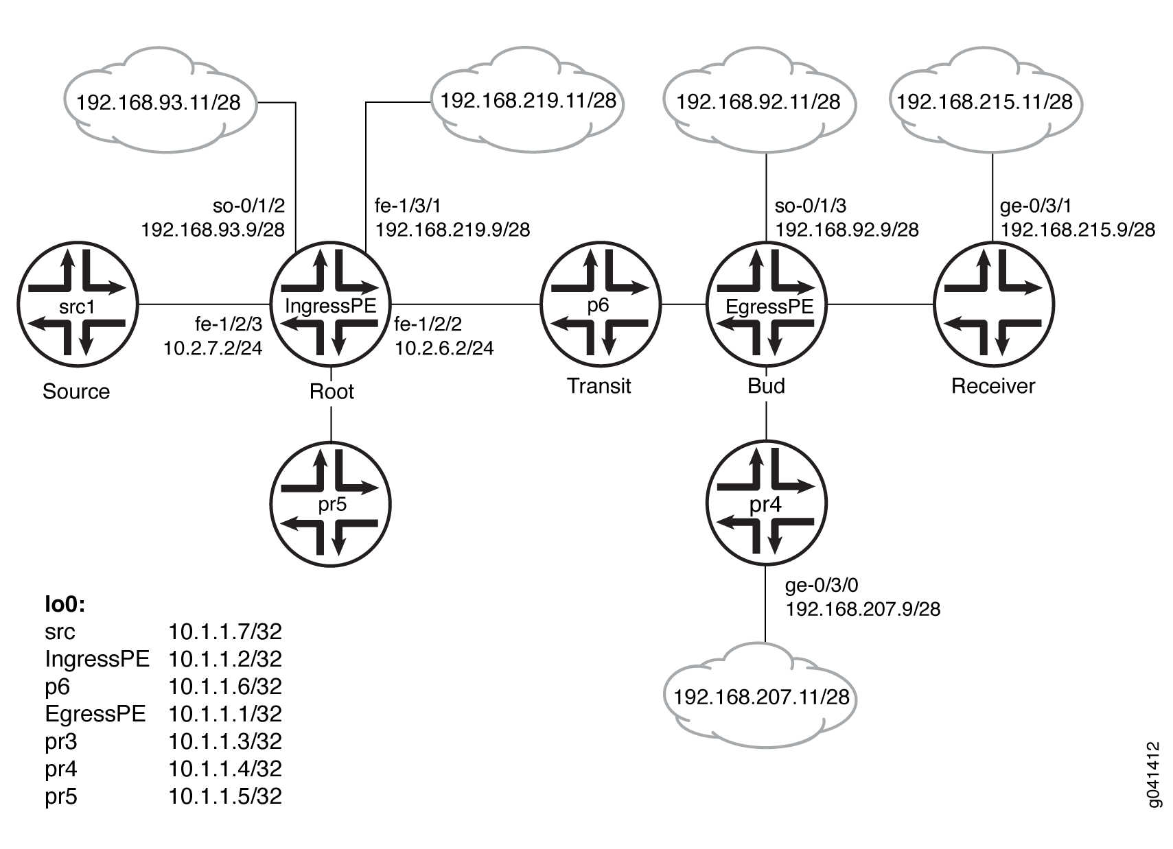
Configuration
Procedure
CLI Quick Configuration
To quickly configure
this example, copy the following commands, paste them into a text
file, remove any line breaks, change any details necessary to match
your network configuration, and then copy and paste the commands into
the CLI at the [edit] hierarchy level.
Device src1
set logical-systems src1 interfaces fe-1/2/0 unit 0 family inet address 10.2.7.7/24
set logical-systems src1 interfaces lo0 unit 0 family inet address 10.1.1.7/32
set logical-systems src1 protocols ospf area 0.0.0.0 interface all
Device IngressPE
set interfaces so-0/1/2 unit 0 family inet address 192.168.93.9/28
set interfaces fe-1/2/0 unit 0 family inet address 10.2.3.2/24
set interfaces fe-1/2/0 unit 0 family mpls
set interfaces fe-1/2/1 unit 0 family inet address 10.2.5.2/24
set interfaces fe-1/2/2 unit 0 family inet address 10.2.6.2/24
set interfaces fe-1/2/2 unit 0 family mpls
set interfaces fe-1/2/3 unit 0 family inet address 10.2.7.2/24
set interfaces fe-1/3/1 unit 0 family inet address 192.168.219.9/28
set interfaces lo0 unit 0 family inet address 10.1.1.2/32
set protocols igmp interface fe-1/2/1.0 version 3
set protocols igmp interface fe-1/2/1.0 static group 232.1.1.1 source 192.168.219.11
set protocols bgp group ibgp type internal
set protocols bgp group ibgp local-address 10.1.1.2
set protocols bgp group ibgp family inet any
set protocols bgp group ibgp family inet-vpn any
set protocols bgp group ibgp neighbor 10.1.1.3
set protocols bgp group ibgp neighbor 10.1.1.4
set protocols bgp group ibgp neighbor 10.1.1.1
set protocols ospf area 0.0.0.0 interface all
set protocols ldp interface fe-1/2/0.0
set protocols ldp interface fe-1/2/2.0
set protocols ldp interface lo0.0
set protocols ldp p2mp
set protocols pim mldp-inband-signalling policy mldppim-ex
set protocols pim rp static address 10.1.1.5
set protocols pim interface fe-1/3/1.0
set protocols pim interface lo0.0
set protocols pim interface fe-1/2/0.21
set protocols pim interface fe-1/2/3.0
set protocols pim interface fe-1/2/1.0
set protocols pim interface so-0/1/2.0
set policy-options policy-statement mldppim-ex term B from source-address-filter 192.168.0.0/24 orlonger
set policy-options policy-statement mldppim-ex term B from source-address-filter 192.168.219.11/32 orlonger
set policy-options policy-statement mldppim-ex term B then accept
set policy-options policy-statement mldppim-ex term A from source-address-filter 10.1.1.7/32 orlonger
set policy-options policy-statement mldppim-ex term A from source-address-filter 10.2.7.0/24 orlonger
set policy-options policy-statement mldppim-ex term A then accept
set routing-options autonomous-system 64510
Device EgressPE
set interfaces so-0/1/3 unit 0 point-to-point
set interfaces so-0/1/3 unit 0 family inet address 192.168.92.9/28
set interfaces fe-1/2/0 unit 0 family inet address 10.1.3.1/24
set interfaces fe-1/2/0 unit 0 family mpls
set interfaces fe-1/2/1 unit 0 family inet address 10.1.4.1/24
set interfaces fe-1/2/2 unit 0 family inet address 10.1.6.1/24
set interfaces fe-1/2/2 unit 0 family mpls
set interfaces fe-1/3/0 unit 0 family inet address 192.168.209.9/28
set interfaces lo0 unit 0 family inet address 10.1.1.1/32
set routing-options autonomous-system 64510
set protocols igmp interface fe-1/3/0.0 version 3
set protocols igmp interface fe-1/3/0.0 static group 232.1.1.1 group-count 3
set protocols igmp interface fe-1/3/0.0 static group 232.1.1.1 source 192.168.219.11
set protocols igmp interface fe-1/3/0.0 static group 227.1.1.1
set protocols igmp interface so-0/1/3.0 version 3
set protocols igmp interface so-0/1/3.0 static group 232.1.1.1 group-count 2
set protocols igmp interface so-0/1/3.0 static group 232.1.1.1 source 192.168.219.11
set protocols igmp interface so-0/1/3.0 static group 232.2.2.2 source 10.2.7.7
set protocols mpls interface fe-1/2/0.0
set protocols mpls interface fe-1/2/2.0
set protocols bgp group ibgp type internal
set protocols bgp group ibgp local-address 10.1.1.1
set protocols bgp group ibgp family inet any
set protocols bgp group ibgp neighbor 10.1.1.2
set protocols msdp local-address 10.1.1.1
set protocols msdp peer 10.1.1.5
set protocols ospf area 0.0.0.0 interface all
set protocols ospf area 0.0.0.0 interface fxp0.0 disable
set protocols ldp interface fe-1/2/0.0
set protocols ldp interface fe-1/2/2.0
set protocols ldp interface lo0.0
set protocols ldp p2mp
set protocols pim mldp-inband-signalling policy mldppim-ex
set protocols pim rp local address 10.1.1.1
set protocols pim rp local group-ranges 227.0.0.0/8
set protocols pim rp static address 10.1.1.4
set protocols pim rp static address 10.2.7.7 group-ranges 226.0.0.0/8
set protocols pim interface lo0.0
set protocols pim interface fe-1/3/0.0
set protocols pim interface fe-1/2/0.0
set protocols pim interface fe-1/2/1.0
set protocols pim interface so-0/1/3.0
set policy-options policy-statement mldppim-ex term B from source-address-filter 192.168.0.0/24 orlonger
set policy-options policy-statement mldppim-ex term B from source-address-filter 192.168.219.11/32 orlonger
set policy-options policy-statement mldppim-ex term B then p2mp-lsp-root address 10.1.1.2
set policy-options policy-statement mldppim-ex term B then accept
set policy-options policy-statement mldppim-ex term A from source-address-filter 10.2.7.0/24 orlonger
set policy-options policy-statement mldppim-ex term A then accept
Device p6
set interfaces fe-1/2/0 unit 0 family inet address 10.1.6.6/24
set interfaces fe-1/2/0 unit 0 family mpls
set interfaces fe-1/2/1 unit 0 family inet address 10.2.6.6/24
set interfaces fe-1/2/1 unit 0 family mpls
set interfaces lo0 unit 0 family inet address 10.1.1.6/32
set interfaces lo0 unit 0 family mpls
set protocols ospf area 0.0.0.0 interface all
set protocols ldp interface fe-1/2/0.0
set protocols ldp interface fe-1/2/1.0
set protocols ldp interface lo0.0
set protocols ldp p2mp
Device pr3
set interfaces ge-0/3/1 unit 0 family inet address 192.168.215.9/28
set interfaces fe-1/2/0 unit 0 family inet address 10.1.3.3/24
set interfaces fe-1/2/0 unit 0 family mpls
set interfaces fe-1/2/1 unit 0 family inet address 10.2.3.3/24
set interfaces fe-1/2/1 unit 0 family mpls
set interfaces lo0 unit 0 family inet address 10.1.1.3/32
set protocols igmp interface ge-0/3/1.0 version 3
set protocols igmp interface ge-0/3/1.0 static group 232.1.1.2 source 192.168.219.11
set protocols igmp interface ge-0/3/1.0 static group 232.2.2.2 source 10.2.7.7
set protocols bgp group ibgp local-address 10.1.1.3
set protocols bgp group ibgp type internal
set protocols bgp group ibgp neighbor 10.1.1.2
set protocols ospf area 0.0.0.0 interface all
set protocols ospf area 0.0.0.0 interface fe-1/2/1.0 metric 2
set protocols ldp interface fe-1/2/0.0
set protocols ldp interface fe-1/2/1.0
set protocols ldp interface lo0.0
set protocols ldp p2mp
set protocols pim mldp-inband-signalling policy mldppim-ex
set protocols pim interface fe-0/3/1.0
set protocols pim interface lo0.0
set policy-options policy-statement mldppim-ex term B from source-address-filter 192.168.0.0/24 orlonger
set policy-options policy-statement mldppim-ex term B from source-address-filter 192.168.219.11/32 orlonger
set policy-options policy-statement mldppim-ex term B then p2mp-lsp-root address 10.1.1.2
set policy-options policy-statement mldppim-ex term B then accept
set policy-options policy-statement mldppim-ex term B from source-address-filter 192.168.0.0/24 orlonger
set policy-options policy-statement mldppim-ex term B from source-address-filter 192.168.219.11/32 orlonger
set policy-options policy-statement mldppim-ex term B from source-address-filter 10.2.7.7/32 orlonger
set policy-options policy-statement mldppim-ex term B then p2mp-lsp-root address 10.1.1.2
set policy-options policy-statement mldppim-ex term B then accept
set routing-options autonomous-system 64510
Device pr4
set interfaces ge-0/3/0 unit 0 family inet address 192.168.207.9/28 set interfaces fe-1/2/0 unit 0 family inet address 10.1.4.4/24 set interfaces fe-1/2/0 unit 0 family iso set interfaces lo0 unit 0 family inet address 10.1.1.4/32 set protocols igmp interface ge-0/3/0.0 version 3 set protocols igmp interface ge-0/3/0.0 static group 232.1.1.2 source 192.168.219.11 set protocols igmp interface ge-0/3/0.0 static group 225.1.1.1 set protocols bgp group ibgp local-address 10.1.1.4 set protocols bgp group ibgp type internal set protocols bgp group ibgp neighbor 10.1.1.2 set protocols msdp local-address 10.1.1.4 set protocols msdp peer 10.1.1.5 set protocols ospf area 0.0.0.0 interface all set protocols pim rp local address 10.1.1.4 set protocols pim interface ge-0/3/0.0 set protocols pim interface lo0.0 set protocols pim interface fe-1/2/0.0 set routing-options autonomous-system 64510
Device pr5
set interfaces fe-1/2/0 unit 0 family inet address 10.2.5.5/24 set interfaces lo0 unit 0 family inet address 10.1.1.5/24 set protocols igmp interface lo0.0 version 3 set protocols igmp interface lo0.0 static group 232.1.1.1 source 192.168.219.11 set protocols msdp local-address 10.1.1.5 set protocols msdp peer 10.1.1.4 set protocols msdp peer 10.1.1.1 set protocols ospf area 0.0.0.0 interface all set protocols pim rp local address 10.1.1.5 set protocols pim interface all
Step-by-Step Procedure
The following example requires you to navigate various levels in the configuration hierarchy. For information about navigating the CLI, see Using the CLI Editor in Configuration Mode in the CLI User Guide.
To configure Device EgressPE:
Configure the interfaces.
Enable MPLS on the core-facing interfaces. On the egress next hops, you do not need to enable MPLS.
[edit interfaces] user@EgressPE# set fe-1/2/0 unit 0 family inet address 10.1.3.1/24 user@EgressPE# set fe-1/2/0 unit 0 family mpls user@EgressPE# set fe-1/2/2 unit 0 family inet address 10.1.6.1/24 user@EgressPE# set fe-1/2/2 unit 0 family mpls user@EgressPE# set so-0/1/3 unit 0 point-to-point user@EgressPE# set so-0/1/3 unit 0 family inet address 192.168.92.9/28 user@EgressPE# set fe-1/2/1 unit 0 family inet address 10.1.4.1/24 user@EgressPE# set fe-1/3/0 unit 0 family inet address 192.168.209.9/28 user@EgressPE# set lo0 unit 0 family inet address 10.1.1.1/32
Configure IGMP on the egress interfaces.
For testing purposes, this example includes static group and source addresses.
[edit protocols igmp] user@EgressPE# set interface fe-1/3/0.0 version 3 user@EgressPE# set interface fe-1/3/0.0 static group 232.1.1.1 group-count 3 user@EgressPE# set interface fe-1/3/0.0 static group 232.1.1.1 source 192.168.219.11 user@EgressPE# set interface fe-1/3/0.0 static group 227.1.1.1 user@EgressPE# set interface so-0/1/3.0 version 3 user@EgressPE# set interface so-0/1/3.0 static group 232.1.1.1 group-count 2 user@EgressPE# set interface so-0/1/3.0 static group 232.1.1.1 source 192.168.219.11 user@EgressPE# set interface so-0/1/3.0 static group 232.2.2.2 source 10.2.7.7
Configure MPLS on the core-facing interfaces.
[edit protocols mpls] user@EgressPE# set interface fe-1/2/0.0 user@EgressPE# set interface fe-1/2/2.0
Configure BGP.
BGP is a policy-driven protocol, so also configure and apply any needed routing policies.
For example, you might want to export static routes into BGP.
[edit protocols bgp group ibgp] user@EgressPE# set type internal user@EgressPE# set local-address 10.1.1.1 user@EgressPE# set family inet any user@EgressPE# set neighbor 10.1.1.2
(Optional) Configure an MSDP peer connection with Device pr5 in order to interconnect the disparate PIM domains, thus enabling redundant RPs.
[edit protocols msdp] user@EgressPE# set local-address 10.1.1.1 user@EgressPE# set peer 10.1.1.5
Configure OSPF.
[edit protocols ospf area 0.0.0.0] user@EgressPE# set interface all user@EgressPE# set interface fxp0.0 disable
Configure LDP on the core-facing interfaces and on the loopback interface.
[edit protocols ldp] user@EgressPE# set interface fe-1/2/0.0 user@EgressPE# set interface fe-1/2/2.0 user@EgressPE# set interface lo0.0
Enable point-to-multipoint MPLS LSPs.
[edit protocols ldp] user@EgressPE# set p2mp
Configure PIM on the downstream interfaces.
[edit protocols pim] user@EgressPE# set interface lo0.0 user@EgressPE# set interface fe-1/3/0.0 user@EgressPE# set interface fe-1/2/1.0 user@EgressPE# set interface so-0/1/3.0
Configure the RP settings because this device serves as the PIM rendezvous point (RP).
[edit protocols pim] user@EgressPE# set rp local address 10.1.1.1 user@EgressPE# set rp local group-ranges 227.0.0.0/8 user@EgressPE# set rp static address 10.1.1.4 user@EgressPE# set rp static address 10.2.7.7 group-ranges 226.0.0.0/8
Enable M-LDP in-band signaling and set the associated policy.
[edit protocols pim] user@EgressPE# set mldp-inband-signalling policy mldppim-ex
Configure the routing policy that specifies the root address for the point-to-multipoint LSP and the associated source addresses.
[edit policy-options policy-statement mldppim-ex] user@EgressPE# set term B from source-address-filter 192.168.0.0/24 orlonger user@EgressPE# set term B from source-address-filter 192.168.219.11/32 orlonger user@EgressPE# set term B then p2mp-lsp-root address 10.1.1.2 user@EgressPE# set term B then accept user@EgressPE# set term A from source-address-filter 10.2.7.0/24 orlonger user@EgressPE# set term A then accept
Configure the autonomous system (AS) ID.
[edit routing-options] user@EgressPE# set autonomous-system 64510
Results
From configuration mode, confirm your configuration
by entering the show interfaces, show protocols, show policy-options, and show routing-options commands. If the output does not display the intended configuration,
repeat the instructions in this example to correct the configuration.
Device EgressPE
user@EgressPE# show interfaces
so-0/1/3 {
unit 0 {
point-to-point;
family inet {
address 192.168.92.9/28;
}
}
}
fe-1/2/0 {
unit 0 {
family inet {
address 10.1.3.1/24;
}
family mpls;
}
}
fe-1/2/1 {
unit 0 {
family inet {
address 10.1.4.1/24;
}
}
}
fe-1/2/2 {
unit 0 {
family inet {
address 10.1.6.1/24;
}
family mpls;
}
}
fe-1/3/0 {
unit 0 {
family inet {
address 192.168.209.9/28;
}
}
}
lo0 {
unit 0 {
family inet {
address 10.1.1.1/32;
}
}
}
user@EgressPE# show protocols
igmp {
interface fe-1/3/0.0 {
version 3;
static {
group 232.1.1.1 {
group-count 3;
source 192.168.219.11;
}
group 227.1.1.1;
}
}
interface so-0/1/3.0 {
version 3;
static {
group 232.1.1.1 {
group-count 2;
source 192.168.219.11;
}
group 232.2.2.2 {
source 10.2.7.7;
}
}
}
}
mpls {
interface fe-1/2/0.0;
interface fe-1/2/2.0;
}
bgp {
group ibgp {
type internal;
local-address 10.1.1.1;
family inet {
any;
}
neighbor 10.1.1.2;
}
}
msdp {
local-address 10.1.1.1;
peer 10.1.1.5;
}
ospf {
area 0.0.0.0 {
interface all;
interface fxp0.0 {
disable;
}
}
}
ldp {
interface fe-1/2/0.0;
interface fe-1/2/2.0;
interface lo0.0;
p2mp;
}
pim {
mldp-inband-signalling {
policy mldppim-ex;
}
rp {
local {
address 10.1.1.1;
group-ranges {
227.0.0.0/8;
}
}
static {
address 10.1.1.4;
address 10.2.7.7 {
group-ranges {
226.0.0.0/8;
}
}
}
}
interface lo0.0;
interface fe-1/3/0.0;
interface fe-1/2/0.0;
interface fe-1/2/1.0;
interface so-0/1/3.0;
}
user@EgressPE# show policy-options
policy-statement mldppim-ex {
term B {
from {
source-address-filter 192.168.0.0/24 orlonger;
source-address-filter 192.168.219.11/32 orlonger;
}
then {
p2mp-lsp-root {
address 10.1.1.2;
}
accept;
}
}
term A {
from {
source-address-filter 10.2.7.0/24 orlonger;
}
then accept;
}
}
user@EgressPE# show routing-options
autonomous-system 64510;
Similarly, configure the other egress devices.
If you are done configuring the devices, enter commit from configuration mode.
Verification
Confirm that the configuration is working properly.
- Checking the PIM Join States
- Checking the PIM Sources
- Checking the LDP Database
- Looking Up the Route Information for the MPLS Label
- Checking the LDP Traffic Statistics
Checking the PIM Join States
Purpose
Display information about PIM join states to verify
the M-LDP in-band upstream and downstream details. On the ingress
device, the show pim join extensive command displays Pseudo-MLDP for the downstream interface. On the
egress, the show pim join extensive command displays Pseudo-MLDP for the upstream interface.
Action
From operational mode, enter the show pim join
extensive command.
user@IngressPE> show pim join extensive
Instance: PIM.master Family: INET
R = Rendezvous Point Tree, S = Sparse, W = Wildcard
Group: 232.1.1.1
Source: 192.168.219.11
Flags: sparse,spt
Upstream interface: fe-1/3/1.0
Upstream neighbor: Direct
Upstream state: Local Source
Keepalive timeout:
Uptime: 1d 23:00:12
Downstream neighbors:
Interface: Pseudo-MLDP
Interface: fe-1/2/1.0
10.2.5.2 State: Join Flags: S Timeout: Infinity
Uptime: 1d 23:00:12 Time since last Join: 1d 23:00:12
Group: 232.1.1.2
Source: 192.168.219.11
Flags: sparse,spt
Upstream interface: fe-1/3/1.0
Upstream neighbor: Direct
Upstream state: Local Source
Keepalive timeout:
Uptime: 1d 22:59:59
Downstream neighbors:
Interface: Pseudo-MLDP
Group: 232.1.1.3
Source: 192.168.219.11
Flags: sparse,spt
Upstream interface: fe-1/3/1.0
Upstream neighbor: Direct
Upstream state: Local Source
Keepalive timeout:
Uptime: 1d 22:07:31
Downstream neighbors:
Interface: Pseudo-MLDP
Group: 232.2.2.2
Source: 10.2.7.7
Flags: sparse,spt
Upstream interface: fe-1/2/3.0
Upstream neighbor: Direct
Upstream state: Local Source
Keepalive timeout:
Uptime: 1d 22:59:59
Downstream neighbors:
Interface: Pseudo-MLDP
user@EgressPE> show pim join extensive
Instance: PIM.master Family: INET
R = Rendezvous Point Tree, S = Sparse, W = Wildcard
Group: 227.1.1.1
Source: *
RP: 10.1.1.1
Flags: sparse,rptree,wildcard
Upstream interface: Local
Upstream neighbor: Local
Upstream state: Local RP
Uptime: 1d 23:14:21
Downstream neighbors:
Interface: fe-1/3/0.0
192.168.209.9 State: Join Flags: SRW Timeout: Infinity
Uptime: 1d 23:14:21 Time since last Join: 1d 20:12:35
Group: 232.1.1.1
Source: 192.168.219.11
Flags: sparse,spt
Upstream protocol: MLDP
Upstream interface: Pseudo MLDP
Upstream neighbor: MLDP LSP root <10.1.1.2>
Upstream state: Join to Source
Keepalive timeout:
Uptime: 1d 23:14:22
Downstream neighbors:
Interface: so-0/1/3.0
192.168.92.9 State: Join Flags: S Timeout: Infinity
Uptime: 1d 20:12:35 Time since last Join: 1d 20:12:35
Downstream neighbors:
Interface: fe-1/3/0.0
192.168.209.9 State: Join Flags: S Timeout: Infinity
Uptime: 1d 20:12:35 Time since last Join: 1d 20:12:35
Group: 232.1.1.2
Source: 192.168.219.11
Flags: sparse,spt
Upstream protocol: MLDP
Upstream interface: Pseudo MLDP
Upstream neighbor: MLDP LSP root <10.1.1.2>
Upstream state: Join to Source
Keepalive timeout:
Uptime: 1d 23:14:22
Downstream neighbors:
Interface: so-0/1/3.0
192.168.92.9 State: Join Flags: S Timeout: Infinity
Uptime: 1d 20:12:35 Time since last Join: 1d 20:12:35
Downstream neighbors:
Interface: fe-1/2/1.0
10.1.4.4 State: Join Flags: S Timeout: 198
Uptime: 1d 22:59:59 Time since last Join: 00:00:12
Downstream neighbors:
Interface: fe-1/3/0.0
192.168.209.9 State: Join Flags: S Timeout: Infinity
Uptime: 1d 20:12:35 Time since last Join: 1d 20:12:35
Group: 232.1.1.3
Source: 192.168.219.11
Flags: sparse,spt
Upstream protocol: MLDP
Upstream interface: Pseudo MLDP
Upstream neighbor: MLDP LSP root <10.1.1.2>
Upstream state: Join to Source
Keepalive timeout:
Uptime: 1d 20:12:35
Downstream neighbors:
Interface: fe-1/3/0.0
192.168.209.9 State: Join Flags: S Timeout: Infinity
Uptime: 1d 20:12:35 Time since last Join: 1d 20:12:35
Group: 232.2.2.2
Source: 10.2.7.7
Flags: sparse,spt
Upstream protocol: MLDP
Upstream interface: Pseudo MLDP
Upstream neighbor: MLDP LSP root <10.1.1.2>
Upstream state: Join to Source
Keepalive timeout:
Uptime: 1d 20:12:35
Downstream neighbors:
Interface: so-0/1/3.0
192.168.92.9 State: Join Flags: S Timeout: Infinity
Uptime: 1d 20:12:35 Time since last Join: 1d 20:12:35
user@pr3> show pim join extensive
Instance: PIM.master Family: INET
R = Rendezvous Point Tree, S = Sparse, W = Wildcard
Group: 232.1.1.2
Source: 192.168.219.11
Flags: sparse,spt
Upstream protocol: MLDP
Upstream interface: Pseudo MLDP
Upstream neighbor: MLDP LSP root <10.1.1.2>
Upstream state: Join to Source
Keepalive timeout:
Uptime: 1d 20:14:40
Downstream neighbors:
Interface: Pseudo-GMP
ge-0/3/1.0
Group: 232.2.2.2
Source: 10.2.7.7
Flags: sparse,spt
Upstream protocol: MLDP
Upstream interface: Pseudo MLDP
Upstream neighbor: MLDP LSP root <10.1.1.2>
Upstream state: Join to Source
Keepalive timeout:
Uptime: 1d 20:14:40
Downstream neighbors:
Interface: Pseudo-GMP
ge-0/3/1.0
user@pr4> show pim join extensive
Instance: PIM.master Family: INET
R = Rendezvous Point Tree, S = Sparse, W = Wildcard
Group: 225.1.1.1
Source: *
RP: 10.1.1.4
Flags: sparse,rptree,wildcard
Upstream interface: Local
Upstream neighbor: Local
Upstream state: Local RP
Uptime: 1d 23:13:43
Downstream neighbors:
Interface: ge-0/3/0.0
192.168.207.9 State: Join Flags: SRW Timeout: Infinity
Uptime: 1d 23:13:43 Time since last Join: 1d 23:13:43
Group: 232.1.1.2
Source: 192.168.219.11
Flags: sparse,spt
Upstream interface: fe-1/2/0.0
Upstream neighbor: 10.1.4.1
Upstream state: Local RP, Join to Source
Keepalive timeout: 0
Uptime: 1d 23:13:43
Downstream neighbors:
Interface: ge-0/3/0.0
192.168.207.9 State: Join Flags: S Timeout: Infinity
Uptime: 1d 23:13:43 Time since last Join: 1d 23:13:43
user@pr5> show pim join extensive
ge-0/3/1.0
Instance: PIM.master Family: INET
R = Rendezvous Point Tree, S = Sparse, W = Wildcard
Instance: PIM.master Family: INET6
R = Rendezvous Point Tree, S = Sparse, W = Wildcard
Checking the PIM Sources
Purpose
Verify that the PIM sources have the expected M-LDP in-band upstream and downstream details.
Action
From operational mode, enter the show pim source command.
user@IngressPE> show pim source
Instance: PIM.master Family: INET
Source 10.1.1.1
Prefix 10.1.1.1/32
Upstream interface Local
Upstream neighbor Local
Source 10.2.7.7
Prefix 10.2.7.0/24
Upstream protocol MLDP
Upstream interface Pseudo MLDP
Upstream neighbor MLDP LSP root <10.1.1.2>
Source 192.168.219.11
Prefix 192.168.219.0/28
Upstream protocol MLDP
Upstream interface Pseudo MLDP
Upstream neighbor MLDP LSP root <10.1.1.2>
user@EgressPE> show pim source
Instance: PIM.master Family: INET
Source 10.2.7.7
Prefix 1.2.7.0/24
Upstream interface fe-1/2/3.0
Upstream neighbor 10.2.7.2
Source 10.2.7.7
Prefix 10.2.7.0/24
Upstream interface fe-1/2/3.0
Upstream neighbor Direct
Source 192.168.219.11
Prefix 192.168.219.0/28
Upstream interface fe-1/3/1.0
Upstream neighbor 192.168.219.9
Source 192.168.219.11
Prefix 192.168.219.0/28
Upstream interface fe-1/3/1.0
Upstream neighbor Direct
user@pr3> show pim source
Instance: PIM.master Family: INET
Source 10.2.7.7
Prefix 1.2.7.0/24
Upstream protocol MLDP
Upstream interface Pseudo MLDP
Upstream neighbor MLDP LSP root <10.1.1.2>
Source 192.168.219.11
Prefix 192.168.219.0/28
Upstream protocol MLDP
Upstream interface Pseudo MLDP
Upstream neighbor MLDP LSP root <10.1.1.2>
user@pr4> show pim source
Instance: PIM.master Family: INET
Source 10.1.1.4
Prefix 10.1.1.4/32
Upstream interface Local
Upstream neighbor Local
Source 192.168.219.11
Prefix 192.168.219.0/28
Upstream interface fe-1/2/0.0
Upstream neighbor 10.1.4.1
Checking the LDP Database
Purpose
Make sure that the show ldp database command displays the expected
root-to-(S,G) bindings.
Action
user@IngressPE> show ldp database
Input label database, 10.255.2.227:0--10.1.1.3:0
Label Prefix
300096 10.1.1.2/32
3 10.1.1.3/32
299856 10.1.1.6/32
299776 10.255.2.227/32
Output label database, 10.255.2.227:0--10.1.1.3:0
Label Prefix
300144 10.1.1.2/32
299776 10.1.1.3/32
299856 10.1.1.6/32
3 10.255.2.227/32
Input label database, 10.255.2.227:0--10.1.1.6:0
Label Prefix
299936 10.1.1.2/32
299792 10.1.1.3/32
3 10.1.1.6/32
299776 10.255.2.227/32
Output label database, 10.255.2.227:0--10.1.1.6:0
Label Prefix
300144 10.1.1.2/32
299776 10.1.1.3/32
299856 10.1.1.6/32
3 10.255.2.227/32
300432 P2MP root-addr 10.1.1.2, grp: 232.2.2.2, src: 10.2.7.7
300288 P2MP root-addr 10.1.1.2, grp: 232.1.1.1, src: 192.168.219.11
300160 P2MP root-addr 10.1.1.2, grp: 232.1.1.2, src: 192.168.219.11
300480 P2MP root-addr 10.1.1.2, grp: 232.1.1.3, src: 192.168.219.11
user@EgressPE> show ldp database
Input label database, 10.1.1.2:0--10.1.1.3:0
Label Prefix
300096 10.1.1.2/32
3 10.1.1.3/32
299856 10.1.1.6/32
299776 10.255.2.227/32
300144 P2MP root-addr 10.1.1.2, grp: 232.2.2.2, src: 10.2.7.7
300128 P2MP root-addr 10.1.1.2, grp: 232.1.1.2, src: 192.168.219.11
Output label database, 10.1.1.2:0--10.1.1.3:0
Label Prefix
3 10.1.1.2/32
299776 10.1.1.3/32
299808 10.1.1.6/32
299792 10.255.2.227/32
Input label database, 10.1.1.2:0--10.1.1.6:0
Label Prefix
299936 10.1.1.2/32
299792 10.1.1.3/32
3 10.1.1.6/32
299776 10.255.2.227/32
300128 P2MP root-addr 10.1.1.2, grp: 232.2.2.2, src: 10.2.7.7
299984 P2MP root-addr 10.1.1.2, grp: 232.1.1.1, src: 192.168.219.11
299952 P2MP root-addr 10.1.1.2, grp: 232.1.1.2, src: 192.168.219.11
300176 P2MP root-addr 10.1.1.2, grp: 232.1.1.3, src: 192.168.219.11
300192 P2MP root-addr 10.1.1.2, grp: ff3e::1:2, src: 2001:db8:abcd::10:2:7:7
Output label database, 10.1.1.2:0--10.1.1.6:0
Label Prefix
3 10.1.1.2/32
299776 10.1.1.3/32
299808 10.1.1.6/32
299792 10.255.2.227/32
-----
logical-system: default
Input label database, 10.255.2.227:0--10.1.1.3:0
Label Prefix
300096 10.1.1.2/32
3 10.1.1.3/32
299856 10.1.1.6/32
299776 10.255.2.227/32
Output label database, 10.255.2.227:0--10.1.1.3:0
Label Prefix
300144 10.1.1.2/32
299776 10.1.1.3/32
299856 10.1.1.6/32
3 10.255.2.227/32
Input label database, 10.255.2.227:0--10.1.1.6:0
Label Prefix
299936 10.1.1.2/32
299792 10.1.1.3/32
3 10.1.1.6/32
299776 10.255.2.227/32
Output label database, 10.255.2.227:0--10.1.1.6:0
Label Prefix
300144 10.1.1.2/32
299776 10.1.1.3/32
299856 10.1.1.6/32
3 10.255.2.227/32
300432 P2MP root-addr 10.1.1.2, grp: 232.2.2.2, src: 10.2.7.7
300288 P2MP root-addr 10.1.1.2, grp: 232.1.1.1, src: 192.168.219.11
300160 P2MP root-addr 10.1.1.2, grp: 232.1.1.2, src: 192.168.219.11
300480 P2MP root-addr 10.1.1.2, grp: 232.1.1.3, src: 192.168.219.11
300496 P2MP root-addr 10.1.1.2, grp: ff3e::1:2, src: 2001:db8:abcd::10:2:7:7user@p6> show ldp database
Input label database, 10.1.1.6:0--10.1.1.2:0
Label Prefix
3 10.1.1.2/32
299776 10.1.1.3/32
299808 10.1.1.6/32
Output label database, 10.1.1.6:0--10.1.1.2:0
Label Prefix
299776 10.1.1.2/32
299792 10.1.1.3/32
3 10.1.1.6/32user@pr3> show ldp database
Input label database, 10.1.1.3:0--10.1.1.2:0
Label Prefix
3 10.1.1.2/32
299776 10.1.1.3/32
299808 10.1.1.6/32
299792 10.255.2.227/32
Output label database, 10.1.1.3:0--10.1.1.2:0
Label Prefix
300096 10.1.1.2/32
3 10.1.1.3/32
299856 10.1.1.6/32
299776 10.255.2.227/32
300144 P2MP root-addr 10.1.1.2, grp: 232.2.2.2, src: 10.2.7.7
300128 P2MP root-addr 10.1.1.2, grp: 232.1.1.2, src: 192.168.219.11
Input label database, 10.1.1.3:0--10.255.2.227:0
Label Prefix
300144 10.1.1.2/32
299776 10.1.1.3/32
299856 10.1.1.6/32
3 10.255.2.227/32
Output label database, 10.1.1.3:0--10.255.2.227:0
Label Prefix
300096 10.1.1.2/32
3 10.1.1.3/32
299856 10.1.1.6/32
299776 10.255.2.227/32
Looking Up the Route Information for the MPLS Label
Purpose
Display the point-to-multipoint FEC information.
Action
user@EgressPE> show route label 299808 detail
mpls.0: 14 destinations, 14 routes (14 active, 0 holddown, 0 hidden)
299808 (1 entry, 1 announced)
*LDP Preference: 9
Next hop type: Flood
Address: 0x931922c
Next-hop reference count: 3
Next hop type: Router, Next hop index: 1109
Address: 0x9318b0c
Next-hop reference count: 2
Next hop: via so-0/1/3.0
Label operation: Pop
Next hop type: Router, Next hop index: 1110
Address: 0x93191e0
Next-hop reference count: 2
Next hop: 192.168.209.11 via fe-1/3/0.0
Label operation: Pop
State: **Active Int AckRequest>
Local AS: 10
Age: 13:08:15 Metric: 1
Validation State: unverified
Task: LDP
Announcement bits (1): 0-KRT
AS path: I
FECs bound to route: P2MP root-addr 10.1.1.2, grp: 232.1.1.1, src: 192.168.219.11Checking the LDP Traffic Statistics
Purpose
Monitor the data traffic statistics for the point-to-multipoint LSP.
Action
user@EgressPE> show ldp traffic-statistics p2mp
P2MP FEC Statistics:
FEC(root_addr:lsp_id/grp,src) Nexthop Packets Bytes Shared
10.1.1.2:232.2.2.2,10.2.7.7 so-0/1/3.0 0 0 No
10.1.1.2:232.1.1.1,192.168.219.11 so-0/1/3.0 0 0 No
fe-1/3/0.0 0 0 No
10.1.1.2:232.1.1.2,192.168.219.11 so-0/1/3.0 0 0 No
fe-1/3/0.0 0 0 No
lt-1/2/0.14 0 0 No
10.1.1.2:232.1.1.3,192.168.219.11 fe-1/3/0.0 0 0 No
10.1.1.2:ff3e::1:2,2001:db8:abcd::1:2:7:7 fe-1/3/0.0 0 0 NoMapping Client and Server for Segment Routing to LDP Interoperability
Segment routing mapping server and client support enables interoperability between network islands that run LDP and segment routing (SR or SPRING). This interoperability is useful during a migration from LDP to SR. During the transition there can be islands (or domains) with devices that support either only LDP, or only segment routing. For these devices to interwork the LDP segment routing mapping server (SRMS) and segment routing mapping client (SRMC) functionality is required. You enable these server and client functions on a device in the segment routing network.
SR mapping server and client functionality is supported with either OSPF or IS-IS.
- Overview of Segment Routing to LDP Interoperability
- Segment Routing to LDP Interoperability Using OSPF
- Interoperability of Segment Routing with LDP Using IS-IS
Overview of Segment Routing to LDP Interoperability
Figure 22 shows a simple LDP network topology to illustrate how interoperability of segment routing devices with LDP devices works. Keep in mind that both OSPF and IS-IS are supported, so for now we'll keep things agnostic with regard to the IGP. The sample topology has six devices, R1 through R6, in a network that is undergoing a migration from LDP to segment routing.
In the topology, devices R1, R2, and R3 are configured for segment routing only. Devices R5 and R6 are part of a legacy LDP domain and do not currently support SR. Device R4 supports both LDP and segment routing. The loopback addresses of all devices are shown. These loopbacks are advertised as egress FECs in the LDP domain and as SR node IDs in the SR domain. Interoperability is based on mapping a LDP FEC into a SR node ID, and vice versa.
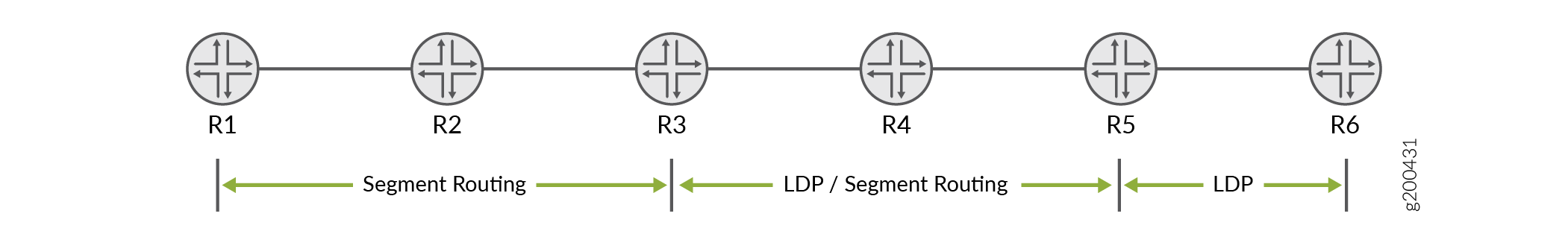
For R1 to interwork with R6, both an LDP segment routing mapping server (SRMS) and a segment routing mapping client (SRMC) are needed. Its easier to understand the role of the SRMS and SRMC by looking at the traffic flow in a unidirectional manner. Based on Figure 22, we'll say that traffic flowing from left to right originates in the SR domain and terminates in the LDP domain. In like fashion, traffic that flows from right to left originates in the LDP domain and terminates in the SR domain.
The SRMS provides the information needed to stitch traffic in the left to right direction. The SRMC provides mapping for traffic that flows from right to left.
- Left to right Traffic Flow: The Segment Routing Mapping Server
The SRMS facilitates LSP stitching between the SR and LDP domains. The server maps LDP FECs into SR node IDs. You configure the LDP FECs to be mapped under the
[edit routing-options source-packet-routing]hierarchy level. Normally you need to map all LDP node loopback addresses for full connectivity. As shown below, you can map contiguous prefixes in a single range statement. If the LDP node loopbacks are not contiguous you need to define multiple mapping statements.You apply the SRMS mapping configuration under the
[edit protocols ospf]or[edit protocols isis]hierarchy level. This choice depends on which IGP is being used. Note that both the SR and LDP nodes share a common, single area/level, IGP routing domain.The SRMS generates an extended prefix list LSA (or LSP in the case of IS-IS). The information in this LSA allows the SR nodes to map LDP prefixes (FECs) to SR Node IDs. The mapped routes for the LDP prefixes are installed in the
inet.3andmpls.0routing tables of the SR nodes to facilitate LSP ingress and stitching operations for traffic in the left to right direction.The extended LSA (or LSP) is flooded throughout the (single) IGP area. This means you are free to place the SRMS configuration on any router in the SR domain. The SRMS node does not have to run LDP.
- Right to Left Traffic Flow: The Segment Routing Mapping Client
To interoperate in the right to left direction, that is, from the LDP island to the SR island, you simply enable segment routing mapping client functionality on a node that speaks both SR and LDP. In our example that is R4. You activate SRMC functionality with the
mapping-clientstatement at the[edit protocols ldp]hierarchy.The SRMC configuration automatically activates an LDP egress policy to advertise the SR domain's node and prefix SIDs as LDP egress FECs. This provides the LDP nodes with LSP reachability to the nodes in the SR domain.
- The SRMC function must be configured on a router that attaches to both the SR and LSP domains. If desired, the same node can also function as the SRMS.
Segment Routing to LDP Interoperability Using OSPF
Refer to Figure 22, assume that device R2 (in the segment routing network) is the SRMS.
-
Define the SRMS function:
[edit routing-options source-packet-routing ] user@R2# set mapping-server-entry ospf-mapping-server prefix-segment-range ldp-lo0s start-prefix 192.168.0.5 user@R2# set mapping-server-entry ospf-mapping-server prefix-segment-range ldp-lo0s start-index 1000 user@R2# set mapping-server-entry ospf-mapping-server prefix-segment-range ldp-lo0s size 2
This configuration creates a mapping block for both the LDP device loopback addresses in the sample topology. The initial Segment ID (SID) index mapped to R5's loopback is
1000. Specifying size2results in SID index 10001 being mapped to R6's loopback address.Note:The IP address used as the
start-prefixis a loopback address of a device in the LDP network (R5, in this example). For full connectivity you must map all the loopback addresses of the LDP routers into the SR domain. If the loopback addresses are contiguous, you can do this with a singleprefix-segment-rangestatement. Non-contiguous loopbacks requires definition of multiple prefix mapping statements.Our example uses contiguous loopbacks so a single
prefix-segment-rangeis shown above. Here's an example of multiple mappings to support the case of two LDP nodes with non-contiguous loopback addressing:[edit routing-options source-packet-routing] show mapping-server-entry map-server-name { prefix-segment-range lo1 { start-prefix 192.168.0.5/32; start-index 1000; size 1; } prefix-segment-range lo2 { start-prefix 192.168.0.10/32; start-index 2000; size 1; } } } -
Next, configure OSPF support for the extended LSA used to flood the mapped prefixes.
[edit protocols] user@R2# set ospf source-packet-routing mapping-server ospf-mapping-server
Once the mapping server configuration is committed on device R2, the extended prefix range TLV is flooded across the OSPF area. The devices capable of segment routing (R1, R2, and R3) install OSPF segment routing routes for the specified loopback address (R5 and R6 in this example), with a segment ID (SID) index. The SID index is also updated in the
mpls.0routing table by the segment routing devices. -
Enable SRMC functionality. For our sample topology you must enable SRMC functionality on R4.
[edit protocols] user@R4# set ldp sr-mapping-client
Once the mapping client configuration is committed on device R4, the SR node IDs and label blocks are advertised as egress FECs to router R5, which then re-advertises them to R6.
Support for stitching segment routing and LDP next-hops with OSPF began in Junos OS 19.1R1.
Unsupported Features and Functionality for Segment Routing interoperability with LDP using OSPF
-
IPv6 prefixes are not supported.
-
Flooding of the OSPF Extended Prefix Opaque LSA across AS boundaries (inter-AS) is not supported.
-
Inter-area LDP mapping server functionality is not supported.
-
ABR functionality of Extended Prefix Opaque LSA is not supported.
-
ASBR functionality of Extended Prefix Opaque LSA is not supported.
-
The segment routing mapping server Preference TLV is not supported.
Interoperability of Segment Routing with LDP Using IS-IS
Refer to Figure 22, assume that device R2 (in the segment routing network) is the SRMS. The following configuration is added for the mapping function:
-
Define the SRMS function:
[edit routing-options source-packet-routing ] user@R2# set mapping-server-entry isis-mapping-server prefix-segment-range ldp-lo0s start-prefix 192.168.0.5 user@R2# set mapping-server-entry isis-mapping-server prefix-segment-range ldp-lo0s start-index 1000 user@R2# set mapping-server-entry isis-mapping-server prefix-segment-range ldp-lo0s size 2
This configuration creates a mapping block for both the LDP device loopback addresses in the sample topology. The initial segment ID (SID) index mapped to R5's loopback is
1000. Specifying size2results in SID index 10001 being mapped to R6's loopback address.Note:The IP address used as the
start-prefixis a loopback address of a device in the LDP network (R5, in this example). For full connectivity you must map all the loopback addresses of the LDP routers in the SR domain. If the loopback addresses are contiguous, you can do this with aprefix-segment-rangestatement. Non-contiguous loopbacks require the definition of multiple mapping statements.Our example uses contiguous loopbacks so a single
prefix-segment-rangeis shown above. Here is an example of prefix mappings to handle the case of two LDP routers with non-contiguous loopback addressing:[edit routing-options source-packet-routing] show mapping-server-entry map-server-name { prefix-segment-range lo1 { start-prefix 192.168.0.5/32; start-index 1000; size 1; } prefix-segment-range lo2 { start-prefix 192.168.0.10/32; start-index 2000; size 1; } } } -
Next, configure IS-IS support for the extended LSP used to flood the mapped prefixes.
[edit protocols] user@R2# set isis source-packet-routing mapping-server isis-mapping-server
Once the mapping server configuration is committed on device R2, the extended prefix range TLV is flooded across the OSPF area. The devices capable of segment routing (R1, R2, and R3) install IS-IS segment routing routes for the specified loopback address (R5 and R6 in this example), with a segment ID (SID) index. The SID index is also updated in the
mpls.0routing table by the segment routing devices. -
Enable SRMC functionality. For our sample topology you must enable SRMC functionality on R4.
[edit protocols] user@R4# set ldp sr-mapping-client
Once the mapping client configuration is committed on device R4, the SR node IDs and label blocks are advertised as egress FECs to router R5, and from there on to R6.
Support for stitching segment routing and LDP next-hops with IS-IS began in Junos OS 17.4R1.
Unsupported Features and Functionality for Interoperability of Segment Routing with LDP using IS-IS
-
Penultimate-hop popping behavior for label binding TLV is not supported.
-
Advertising of range of prefixes in label binding TLV is not supported.
-
Segment Routing Conflict Resolution is not supported.
-
LDP traffic statistics does not work.
-
Nonstop active routing (NSR) and graceful Routing Engine switchover (GRES) is not supported.
-
IS-IS inter-level is not supported.
-
RFC 7794, IS-IS Prefix Attributes for Extended IPv4 is not supported.
-
Redistributing LDP route as a prefix-sid at the stitching node is not supported.
Miscellaneous LDP Properties
The following sections describe how to configure a number of miscellaneous LDP properties.
- Configure LDP to Use the IGP Route Metric
- Prevent Addition of Ingress Routes to the inet.0 Routing Table
- Multiple-Instance LDP and Carrier-of-Carriers VPNs
- Configure MPLS and LDP to Pop the Label on the Ultimate-Hop Router
- Enable LDP over RSVP-Established LSPs
- Enable LDP over RSVP-Established LSPs in Heterogeneous Networks
- Configure the TCP MD5 Signature for LDP Sessions
- Configuring LDP Session Protection
- Disabling SNMP Traps for LDP
- Configuring LDP Synchronization with the IGP on LDP Links
- Configuring LDP Synchronization with the IGP on the Router
- Configuring the Label Withdrawal Timer
- Ignoring the LDP Subnet Check
Configure LDP to Use the IGP Route Metric
Use the track-igp-metric statement if you want the interior gateway
protocol (IGP) route metric to be used for the LDP routes instead of the default LDP
route metric (the default LDP route metric is 1).
To use the IGP route metric, include the
track-igp-metric
statement:
track-igp-metric;
For a list of hierarchy levels at which you can include this statement, see the statement summary section for this statement.
Prevent Addition of Ingress Routes to the inet.0 Routing Table
By configuring the no-forwarding statement, you can prevent ingress
routes from being added to the inet.0 routing table instead of the inet.3 routing
table even if you enabled the traffic-engineering bgp-igp statement
at the [edit protocols mpls] or the [edit logical-systems
logical-system-name protocols mpls] hierarchy
level. By default, the no-forwarding statement is disabled.
ACX Series routers do not support the [edit logical-systems]
hierarchy level.
To omit ingress routes from the inet.0 routing table, include the
no-forwarding
statement:
no-forwarding;
For a list of hierarchy levels at which you can include this statement, see the statement summary section for this statement.
Multiple-Instance LDP and Carrier-of-Carriers VPNs
By configuring multiple LDP routing instances, you can use LDP to advertise labels in a carrier-of-carriers VPN from a service provider provider edge (PE) router to a customer carrier customer edge (CE) router. This is especially useful when the carrier customer is a basic Internet service provider (ISP) and wants to restrict full Internet routes to its PE routers. By using LDP instead of BGP, the carrier customer shields its other internal routers from the Internet. Multiple-instance LDP is also useful when a carrier customer wants to provide Layer 2 or Layer 3 VPN services to its customers.
For an example of how to configure multiple LDP routing instances for carrier-of-carriers VPNs, see the Multiple Instances for Label Distribution Protocol User Guide.
Configure MPLS and LDP to Pop the Label on the Ultimate-Hop Router
The default advertised label is label 3 (Implicit Null label). If label 3 is advertised, the penultimate-hop router removes the label and sends the packet to the egress router. If ultimate-hop popping is enabled, label 0 (IPv4 Explicit Null label) is advertised. Ultimate-hop popping ensures that any packets traversing an MPLS network include a label.
To configure ultimate-hop popping, include the
explicit-null
statement:
explicit-null;
For a list of hierarchy levels at which you can include this statement, see the statement summary section for this statement.
Juniper Networks routers queue packets based on the incoming label. Routers from other vendors might queue packets differently. Keep this in mind when working with networks containing routers from multiple vendors.
For more information about labels, see MPLS Label Overview and MPLS Label Allocation.
Enable LDP over RSVP-Established LSPs
You can run LDP over LSPs established by RSVP, effectively tunneling the
LDP-established LSP through the one established by RSVP. To do so, enable LDP on the
lo0.0 interface (see Enabling and
Disabling LDP). You must also configure the LSPs over which you want LDP
to operate by including the ldp-tunneling statement at the
[edit protocols mpls
label-switched-path
lsp-name] hierarchy level:
[edit]
protocols {
mpls {
label-switched-path lsp-name {
from source;
to destination;
ldp-tunneling;
}
}
}
For a list of hierarchy levels at which you can include this statement, see the statement summary section for this statement.
LDP can be tunneled over a RSVP session that has link protection enabled. Starting with Junos OS Release 21.1R1, displaying details about the LDP tunneled route displays both the primary and bypass LSP next hops. In prior Junos OS releases, the bypass LSP next hop displayed the next hop for the primary LSP.
Enable LDP over RSVP-Established LSPs in Heterogeneous Networks
Some other vendors use an OSPF metric of 1 for the loopback address. Juniper Networks routers use an OSPF metric of 0 for the loopback address. This might require that you manually configure the RSVP metric when deploying LDP tunneling over RSVP LSPs in heterogeneous networks.
When a Juniper Networks router is linked to another vendor’s router through an RSVP tunnel, and LDP tunneling is also enabled, by default the Juniper Networks router might not use the RSVP tunnel to route traffic to the LDP destinations downstream of the other vendor’s egress router if the RSVP path has a metric of 1 larger than the physical OSPF path.
To ensure that LDP tunneling functions properly in heterogeneous networks, you can
configure OSPF to ignore the RSVP LSP metric by including the
ignore-lsp-metrics
statement:
ignore-lsp-metrics;
You can configure this statement at the following hierarchy levels:
-
[edit protocols ospf traffic-engineering shortcuts] -
[edit logical-systems logical-system-name protocols ospf traffic-engineering shortcuts]
ACX Series routers do not support the [edit logical-systems]
hierarchy level.
To enable LDP over RSVP LSPs, you also still need to complete the procedure in Section Enable LDP over RSVP-Established LSPs.
Configure the TCP MD5 Signature for LDP Sessions
You can configure an MD5 signature for an LDP TCP connection to protect against the introduction of spoofed TCP segments into LDP session connection streams. For more information about TCP authentication, see TCP. For how to use TCP Authentication Option (TCP-AO) instead of TCP MD5, see TCP Authentication Option (TCP-AO).
A router using the MD5 signature option is configured with a password for each peer for which authentication is required. The password is stored encrypted.
LDP hello adjacencies can still be created even when peering interfaces are configured with different security signatures. However, the TCP session cannot be authenticated and is never established.
You can configure Hashed Message Authentication Code (HMAC) and MD5 authentication for LDP sessions as a per-session configuration or a subnet match (that is, longest prefix match) configuration. The support for subnet-match authentication provides flexibility in configuring authentication for automatically targeted LDP (TLDP) sessions. This makes the deployment of remote loop-free alternate (LFA) and FEC 129 pseudowires easy.
To configure an MD5 signature for an LDP TCP connection, include the
authentication-key
statement as part of the session group:
[edit protocols ldp]
session-group prefix-length {
authentication-key md5-authentication-key;
}
Use the session-group statement to configure the address for the
remote end of the LDP session.
The md5-authentication-key, or password, in the
configuration can be up to 69 characters long. Characters can include any ASCII
strings. If you include spaces, enclose all characters in quotation marks.
You can also configure an authentication key update mechanism for the LDP routing protocol. This mechanism allows you to update authentication keys without interrupting associated routing and signaling protocols such as Open Shortest Path First (OSPF) and Resource Reservation Setup Protocol (RSVP).
To configure the authentication key update mechanism, include the
key-chain statement at the [edit security
authentication-key-chains] hierarchy level, and specify the
key option to create a keychain consisting of several
authentication keys.
[edit security authentication-key-chains]
key-chain key-chain-name {
key key {
secret secret-data;
start-time yyyy-mm-dd.hh:mm:ss;
}
}
To configure the authentication key update mechanism for the LDP routing protocol,
include the
authentication-key-chain
statement at the [edit protocols ldp] hierarchy level to
associate the protocol with the [edit security
suthentication-key-chains] authentication keys. You must also configure
the authentication algorithm by including the authentication-algorithm
algorithm statement the [edit protocols
ldp] hierarchy level.
[edit protocols ldp]
group group-name {
neighbor address {
authentication-algorithm algorithm;
authentication-key-chain key-chain-name;
}
}
For more information about the authentication key update feature, see Configuring the Authentication Key Update Mechanism for BGP and LDP Routing Protocols.
Configuring LDP Session Protection
An LDP session is normally created between a pair of routers that are connected by one or more links. The routers form one hello adjacency for every link that connects them and associate all the adjacencies with the corresponding LDP session. When the last hello adjacency for an LDP session goes away, the LDP session is terminated. You might want to modify this behavior to prevent an LDP session from being unnecessarily terminated and reestablished.
You can configure the Junos OS to leave the LDP session between two routers up even
if there are no hello adjacencies on the links connecting the two routers by
configuring the session-protection statement. You can optionally
specify a time in seconds using the timeout option. The session
remains up for the duration specified as long as the routers maintain IP network
connectivity.
session-protection { timeout seconds; }
For a list of hierarchy levels at which you can include this statement, see the statement summary section.
Disabling SNMP Traps for LDP
Whenever an LDP LSP makes a transition from up to down, or down to up, the router sends an SNMP trap. However, it is possible to disable the LDP SNMP traps on a router, logical system, or routing instance.
For information about the LDP SNMP traps and the proprietary LDP MIB, see the SNMP MIB Explorer..
To disable SNMP traps for LDP, specify the trap disable option for
the log-updown statement:
log-updown { trap disable; }
For a list of hierarchy levels at which you can include this statement, see the statement summary section for this statement.
Configuring LDP Synchronization with the IGP on LDP Links
LDP is a protocol for distributing labels in non-traffic-engineered applications. Labels are distributed along the best path determined by the IGP. If synchronization between LDP and the IGP is not maintained, the LSP goes down. When LDP is not fully operational on a given link (a session is not established and labels are not exchanged), the IGP advertises the link with the maximum cost metric. The link is not preferred but remains in the network topology.
LDP synchronization is supported only on active point-to-point interfaces and LAN interfaces configured as point-to-point under the IGP. LDP synchronization is not supported during graceful restart.
To advertise the maximum cost metric until LDP is operational for synchronization,
include the ldp-synchronization statement:
ldp-synchronization { disable; hold-time seconds; }
To disable synchronization, include the disable statement. To
configure the time period to advertise the maximum cost metric for a link that is
not fully operational, include the hold-time statement.
For a list of hierarchy levels at which you can configure this statement, see the statement summary section for this statement.
Configuring LDP Synchronization with the IGP on the Router
You can configure the time the LDP waits before informing the IGP that the LDP neighbor and session for an interface are operational. For large networks with numerous FECs, you might need to configure a longer value to allow enough time for the LDP label databases to be exchanged.
To configure the time the LDP waits before informing the IGP that the LDP neighbor
and session are operational, include the igp-synchronization
statement and specify a time in seconds for the holddown-interval
option:
igp-synchronization holddown-interval seconds;
For a list of hierarchy levels at which you can configure this statement, see the statement summary section for this statement.
Configuring the Label Withdrawal Timer
The label withdrawal timer delays sending a label withdrawal message for a FEC to a
neighbor. When an IGP link to a neighbor fails, the label associated with the FEC
has to be withdrawn from all the upstream routers if the neighbor is the next hop
for the FEC. After the IGP converges and a label is received from a new next hop,
the label is readvertised to all the upstream routers. This is the typical network
behavior. By delaying label withdrawal by a small amount of time (for example, until
the IGP converges and the router receives a new label for the FEC from the
downstream next hop), the label withdrawal and sending a label mapping soon could be
avoided. The label-withdrawal-delay statement allows you to
configure this delay time. By default, the delay is 60 seconds.
If the router receives the new label before the timer runs out, the label withdrawal timer is canceled. However, if the timer runs out, the label for the FEC is withdrawn from all of the upstream routers.
By default, LDP waits for 60 seconds before withdrawing labels to avoid resignaling
LSPs multiple times while the IGP is reconverging. To configure the label withdrawal
delay time in seconds, include the label-withdrawal-delay
statement:
label-withdrawal-delay seconds;
For a list of hierarchy levels at which you can configure this statement, see the statement summary section for this statement.
Ignoring the LDP Subnet Check
In Junos OS Release 8.4 and later releases, an LDP source address subnet check is performed during the neighbor establishment procedure. The source address in the LDP link hello packet is matched against the interface address. This causes an interoperability issue with some other vendors’ equipment.
To disable the subnet check, include the allow-subnet-mismatch
statement:
allow-subnet-mismatch;
This statement can be included at the following hierarchy levels:
-
[edit protocols ldp interface interface-name] -
[edit logical-systems logical-system-name protocols ldp interface interface-name]
ACX Series routers do not support [edit logical-systems]
hierarchy level.
See Also
Configuring LDP LSP Traceroute
You can trace the route followed by an LDP-signaled LSP. LDP LSP traceroute is based on RFC 4379, Detecting Multi-Protocol Label Switched (MPLS) Data Plane Failures. This feature allows you to periodically trace all paths in a FEC. The FEC topology information is stored in a database accessible from the CLI.
A topology change does not automatically trigger a trace of an LDP LSP. However, you can manually initiate a traceroute. If the traceroute request is for an FEC that is currently in the database, the contents of the database are updated with the results.
The periodic traceroute feature applies to all FECs specified
by the oam statement configured at the [edit protocols
ldp] hierarchy level. To configure periodic LDP LSP traceroute,
include the periodic-traceroute statement:
periodic-traceroute { disable; exp exp-value; fanout fanout-value; frequency minutes; paths number-of-paths; retries retry-attempts; source address; ttl ttl-value; wait seconds; }
You can configure this statement at the following hierarchy levels:
You can configure the periodic-traceroute statement
by itself or with any of the following options:
exp—Specify the class of service to use when sending probes.fanout—Specify the maximum number of next hops to search per node.frequency—Specify the interval between traceroute attempts.paths—Specify the maximum number of paths to search.retries—Specify the number of attempts to send a probe to a specific node before giving up.source—Specify the IPv4 source address to use when sending probes.ttl—Specify the maximum time-to-live value. Nodes that are beyond this value are not traced.wait—Specify the wait interval before resending a probe packet.
Collecting LDP Statistics
LDP traffic statistics show the volume of traffic that has passed through a particular FEC on a router.
When you configure the traffic-statistics statement
at the [edit protocols ldp] hierarchy level, the LDP traffic
statistics are gathered periodically and written to a file. You can
configure how often statistics are collected (in seconds) by
using the interval option. The default collection interval
is 5 minutes. You must configure an LDP statistics file; otherwise,
LDP traffic statistics are not gathered. If the LSP goes down, the
LDP statistics are reset.
To collect LDP traffic statistics, include the traffic-statistics statement:
traffic-statistics { file filename <files number> <size size> <world-readable | no-world-readable>; interval interval; no-penultimate-hop; }
For a list of hierarchy levels at which you can include this statement, see the statement summary section for this statement.
This section includes the following topics:
- LDP Statistics Output
- Disabling LDP Statistics on the Penultimate-Hop Router
- LDP Statistics Limitations
LDP Statistics Output
The following sample output is from an LDP statistics file:
FEC Type Packets Bytes Shared
10.255.350.448/32 Transit 0 0 No
Ingress 0 0 No
10.255.350.450/32 Transit 0 0 Yes
Ingress 0 0 No
10.255.350.451/32 Transit 0 0 No
Ingress 0 0 No
220.220.220.1/32 Transit 0 0 Yes
Ingress 0 0 No
220.220.220.2/32 Transit 0 0 Yes
Ingress 0 0 No
220.220.220.3/32 Transit 0 0 Yes
Ingress 0 0 No
May 28 15:02:05, read 12 statistics in 00:00:00 seconds
The LDP statistics file includes the following columns of data:
FEC—FEC for which LDP traffic statistics are collected.Type—Type of traffic originating from a router, eitherIngress(originating from this router) orTransit(forwarded through this router).Packets—Number of packets passed by the FEC since its LSP came up.Bytes—Number of bytes of data passed by the FEC since its LSP came up.Shared—AYesvalue indicates that several prefixes are bound to the same label (for example, when several prefixes are advertised with an egress policy). The LDP traffic statistics for this case apply to all the prefixes and should be treated as such.read—This number (which appears next to the date and time) might differ from the actual number of the statistics displayed. Some of the statistics are summarized before being displayed.
Disabling LDP Statistics on the Penultimate-Hop Router
Gathering LDP traffic statistics at the penultimate-hop router
can consume excessive system resources, on next-hop routes in particular.
This problem is exacerbated if you have configured the deaggregate statement in addition to the traffic-statistics statement.
For routers reaching their limit of next-hop route usage, we recommend
configuring the no-penultimate-hop option for the traffic-statistics statement:
traffic-statistics { no-penultimate-hop; }
For a list of hierarchy levels at which you can configure the traffic-statistics statement, see the statement summary section
for this statement.
When you configure the no-penultimate-hop option,
no statistics are available for the FECs that are the penultimate
hop for this router.
Whenever you include or remove this option from the configuration, the LDP sessions are taken down and then restarted.
The following sample output is from an LDP statistics file showing
routers on which the no-penultimate-hop option is configured:
FEC Type Packets Bytes Shared
10.255.245.218/32 Transit 0 0 No
Ingress 4 246 No
10.255.245.221/32 Transit statistics disabled
Ingress statistics disabled
13.1.1.0/24 Transit statistics disabled
Ingress statistics disabled
13.1.3.0/24 Transit statistics disabled
Ingress statistics disabled
LDP Statistics Limitations
The following are issues related to collecting LDP statistics
by configuring the traffic-statistics statement:
You cannot clear the LDP statistics.
If you shorten the specified interval, a new LDP statistics request is issued only if the statistics timer expires later than the new interval.
A new LDP statistics collection operation cannot start until the previous one has finished. If the interval is short or if the number of LDP statistics is large, the time gap between the two statistics collections might be longer than the interval.
When an LSP goes down, the LDP statistics are reset.
Tracing LDP Protocol Traffic
The following sections describe how to configure the trace options to examine LDP protocol traffic:
- Tracing LDP Protocol Traffic at the Protocol and Routing Instance Levels
- Tracing LDP Protocol Traffic Within FECs
- Examples: Tracing LDP Protocol Traffic
Tracing LDP Protocol Traffic at the Protocol and Routing Instance Levels
To trace LDP protocol traffic, you can specify options in the
global traceoptions statement at the [edit routing-options] hierarchy level, and you can specify LDP-specific options by including
the traceoptions statement:
traceoptions { file filename <files number> <size size> <world-readable | no-world-readable>; flag flag <flag-modifier> <disable>; }
For a list of hierarchy levels at which you can include this statement, see the statement summary section for this statement.
Use the file statement to specify the name of the
file that receives the output of the tracing operation. All files
are placed in the directory /var/log. We recommend that you place
LDP-tracing output in the file ldp-log.
The following trace flags display the operations associated with the sending and receiving of various LDP messages. Each can carry one or more of the following modifiers:
address—Trace the operation of address and address withdrawal messages.binding—Trace label-binding operations.error—Trace error conditions.event—Trace protocol events.initialization—Trace the operation of initialization messages.label—Trace the operation of label request, label map, label withdrawal, and label release messages.notification—Trace the operation of notification messages.packets—Trace the operation of address, address withdrawal, initialization, label request, label map, label withdrawal, label release, notification, and periodic messages. This modifier is equivalent to setting theaddress,initialization,label,notification, andperiodicmodifiers.You can also configure the
filterflag modifier with thematch-on addresssub-option for thepacketsflag. This allows you to trace based on the source and destination addresses of the packets.path—Trace label-switched path operations.path—Trace label-switched path operations.periodic—Trace the operation of hello and keepalive messages.route—Trace the operation of route messages.state—Trace protocol state transitions.
Tracing LDP Protocol Traffic Within FECs
LDP associates a forwarding equivalence class (FEC) with each LSP it creates. The FEC associated with an LSP specifies which packets are mapped to that LSP. LSPs are extended through a network as each router chooses the label advertised by the next hop for the FEC and splices it to the label it advertises to all other routers.
You can trace LDP protocol traffic within a specific FEC and
filter LDP trace statements based on an FEC. This is useful when you
want to trace or troubleshoot LDP protocol traffic associated with
an FEC. The following trace flags are available for this purpose: route, path, and binding.
The following example illustrates how you might configure the
LDP traceoptions statement to filter LDP trace statements
based on an FEC:
[edit protocols ldp traceoptions] set flag route filter match-on fec policy "filter-policy-for-ldp-fec";
This feature has the following limitations:
The filtering capability is only available for FECs composed of IP version 4 (IPv4) prefixes.
Layer 2 circuit FECs cannot be filtered.
When you configure both route tracing and filtering, MPLS routes are not displayed (they are blocked by the filter).
Filtering is determined by the policy and the configured value for the
match-onoption. When configuring the policy, be sure that the default behavior is alwaysreject.The only
match-onoption isfec. Consequently, the only type of policy you should include is a route-filter policy.
Examples: Tracing LDP Protocol Traffic
Trace LDP path messages in detail:
[edit]
protocols {
ldp {
traceoptions {
file ldp size 10m files 5;
flag path;
}
}
}
Trace all LDP outgoing messages:
[edit]
protocols {
ldp {
traceoptions {
file ldp size 10m files 5;
flag packets;
}
}
}
Trace all LDP error conditions:
[edit]
protocols {
ldp {
traceoptions {
file ldp size 10m files 5;
flag error;
}
}
}
Trace all LDP incoming messages and all label-binding operations:
[edit]
protocols {
ldp {
traceoptions {
file ldp size 10m files 5 world-readable;
flag packets receive;
flag binding;
}
interface all {
}
}
}
Trace LDP protocol traffic for an FEC associated with the LSP:
[edit]
protocols {
ldp {
traceoptions {
flag route filter match-on fec policy filter-policy-for-ldp-fec;
}
}
}
Change History Table
Feature support is determined by the platform and release you are using. Use Feature Explorer to determine if a feature is supported on your platform.