LSP Labels
MPLS Label Overview
Packets traveling along an LSP are identified by a label—a 20-bit, unsigned integer in the range 0 through 1,048,575. For push labels on ingress routers, no labels in this range are restricted. For incoming labels on the transit static LSP, the label value is restricted to 1,000,000 through 1,048,575.
On MX Series, PTX Series, and T Series routers, the value for entropy and flow labels is restricted to 16 through 1,048,575.
MPLS Label Allocation
In the Junos OS, label values are allocated per router or switch—the
rest of this explanation uses router to cover both. The display output
shows only the label (for example, 01024). Labels for multicast packets are independent of those for unicast
packets. Currently, the Junos OS does not support multicast labels.
Labels are assigned by downstream routers relative to the flow of packets. A router receiving labeled packets (the next-hop router) is responsible for assigning incoming labels. A received packet containing a label that is unrecognized (unassigned) is dropped. For unrecognized labels, the router does not attempt to unwrap the label to analyze the network layer header, nor does it generate an Internet Control Message Protocol (ICMP) destination unreachable message.
A packet can carry a number of labels, organized as a last-in, first-out stack. This is referred to as a label stack. At a particular router, the decision about how to forward a labeled packet is based exclusively on the label at the top of the stack.
Figure 1 shows the encoding of a single label. The encoding appears after data link layer headers, but before any network layer header.
Figure 2 illustrates the purpose of the class-of-service bits (also known as the EXP or experimental bits). Bits 20 and 21 specify the queue number. Bit 22 is the packet loss priority (PLP) bit used to specify the random early detection (RED) drop profile. For more information about class of service and the class-of-service bits, see Configuring Class of Service for MPLS LSPs.
Operations on MPLS Labels
The router supports the following label operations:
Push—Add a new label to the top of the packet. For IPv4 packets, the new label is the first label. The time-to-live (TTL) and s bits are derived from the IP packet header. The MPLS class of service (CoS) is derived from the queue number. If the push operation is performed on an existing MPLS packet, you will have a packet with two or more labels. This is called label stacking. The top label must have its s bit set to 0, and might derive CoS and TTL from lower levels. The new top label in a label stack always initializes its TTL to 255, regardless of the TTL value of lower labels.
Pop—Remove the label from the beginning of the packet. Once the label is removed, the TTL is copied from the label into the IP packet header, and the underlying IP packet is forwarded as a native IP packet. In the case of multiple labels in a packet (label stacking), removal of the top label yields another MPLS packet. The new top label might derive CoS and TTL from a previous top label. The popped TTL value from the previous top label is not written back to the new top label.
Swap—Replace the label at the top of the label stack with a new label. The S and CoS bits are copied from the previous label, and the TTL value is copied and decremented (unless the
no-decrement-ttlorno-propagate-ttlstatement is configured). A transit router supports a label stack of any depth.Multiple Push—Add multiple labels (up to three) on top of existing packets. This operation is equivalent to pushing multiple times.
Swap and Push—Replace the existing top of the label stack with a new label, and then push another new label on top.
Understanding MPLS Label Operations
In the traditional packet-forwarding paradigm, as a packet travels from one switch to the next, an independent forwarding decision is made at each hop. The IP network header is analyzed and the next hop is chosen based on this analysis and on the information in the routing table. In an MPLS environment, the analysis of the packet header is made only once, when a packet enters the MPLS tunnel (that is, the path used for MPLS traffic).
When an IP packet enters a label-switched path (LSP), the ingress provider edge (PE) switch examines the packet and assigns it a label based on its destination, placing the label in the packet’s header. The label transforms the packet from one that is forwarded based on its IP routing information to one that is forwarded based on information associated with the label. The packet is then forwarded to the next provider switch in the LSP. This switch and all subsequent switches in the LSP do not examine any of the IP routing information in the labeled packet. Rather, they use the label to look up information in their label forwarding table. They then replace the old label with a new label and forward the packet to the next switch in the path. When the packet reaches the egress PE switch, the label is removed, and the packet again becomes a native IP packet and is forwarded based on its IP routing information.
This topic describes:
- MPLS Label-Switched Paths and MPLS Labels
- Reserved Labels
- MPLS Label Operations
- Penultimate-Hop Popping and Ultimate-Hop Popping
MPLS Label-Switched Paths and MPLS Labels
When a packet enters the MPLS network, it is assigned to an LSP. Each LSP is identified by a label, which is a short (20-bit), fixed-length value at the front of the MPLS label (32 bits). Labels are used as lookup indexes for the label forwarding table. For each label, this table stores forwarding information. Because no additional parsing or lookup is done on the encapsulated packet, MPLS supports the transmission of any other protocols within the packet payload.
Figure 3 shows the encoding of a single label. The encoding appears after data link layer headers, but before any network layer header.
Reserved Labels
Labels range from 0 through 1,048,575. Labels 0 through 999,999 are for internal use.
Some of the reserved labels (in the range 0 through 15) have well-defined meanings. The following reserved labels are used by QFX Series and EX4600 devices:
-
0, IPv4 Explicit Null label—This value is valid only when it is the sole label entry (no label stacking). It indicates that the label must be popped on receipt. Forwarding continues based on the IP version 4 (IPv4) packet.
-
1, Router Alert label—When a packet is received with a top label value of 1, it is delivered to the local software module for processing.
-
3, Implicit Null label—This label is used in the signaling protocol (RSVP) only to request label popping by the downstream switch. It never actually appears in the encapsulation. Labels with a value of 3 must not be used in the data packet as real labels. No payload type (IPv4 or IPv6) is implied with this label.
MPLS Label Operations
QFX Series and EX4600 devices support the following MPLS label operations:
-
Push
-
Pop
-
Swap
There is a limit with regard to the number of labels that QFX and EX4600 devices can affix (push operations) to the label stack or remove (pop operations) from the label stack.
-
For Push operations—As many as three labels are supported.
-
For Pop operations—As many as three labels are supported.
The push operation affixes a new label to the top of the IP packet. For IPv4 packets, the new label is the first label. The time to live (TTL) field value in the packet header is derived from the IP packet header. The push operation cannot be applied to a packet that already has an MPLS label.
The pop operation removes a label from the beginning of the packet. Once the label is removed, the TTL is copied from the label into the IP packet header, and the underlying IP packet is forwarded as a native IP packet
The swap operation removes an existing MPLS label from an IP packet and replaces it with a new MPLS label, based on the following:
-
Incoming interface
-
Label
-
Label forwarding table
Figure 4 shows an IP packet without a label arriving on the customer edge interface (ge-0/0/1) of the ingress PE switch. The ingress PE switch examines the packet and identifies that packet’s destination as the egress PE switch. The ingress PE switch applies label 100 to the packet and sends the MPLS packet to its outgoing MPLS core interface (ge-0/0/5). The MPLS packet is transmitted on the MPLS tunnel through the provider switch, where it arrives at interface ge-0/0/5 with label 100. The provider switch swaps label 100 with label 200 and forwards the MPLS packet through its core interface (ge-0/0/7) to the next hop on the tunnel, which is the egress PE switch. The egress PE switch receives the MPLS packet through its core interface (ge-0/0/7), removes the MPLS label, and sends the IP packet out of its customer edge interface (ge-0/0/1) to a destination that is beyond the tunnel.
Figure 4 shows the path of a packet as it passes in one direction from the ingress PE switch to the egress PE switch. However, the MPLS configuration also allows traffic to travel in the reverse direction. Thus, each PE switch operates as both an ingress switch and an egress switch.
Penultimate-Hop Popping and Ultimate-Hop Popping
The switches enable penultimate-hop popping (PHP) by default with IP over MPLS configurations. With PHP, the penultimate provider switch is responsible for popping the MPLS label and forwarding the traffic to the egress PE switch. The egress PE switch then performs an IP route lookup and forwards the traffic. This reduces the processing load on the egress PE switch, because it is not responsible for popping the MPLS label.
-
The default advertised label is label 3 (Implicit Null label). If label 3 is advertised, the penultimate-hop switch removes the label and sends the packet to the egress PE switch.
-
If ultimate-hop popping is enabled, label 0 (IPv4 Explicit Null label) is advertised and the egress PE switch of the LSP removes the label.
Understanding MPLS Label Manager
MPLS label manager is used to manage different label
types such as LSI, dynamic, block, and static, which are supported
on platforms using Modular Port Concentrators (MPCs) equipped with
Junos Trio chipsets. These line cards provide more flexibility and
scalability, when the enhanced-ip command is configured
on the device.
The existing behavior of label-space command is retained,
which is not recommended. To provide additional
functionality such as multiple ranges for each type of label, label-range command is introduced under the [edit protocols
mpls label usage] hierarchy, which is independent of label-space configuration. You can choose either style if only one range is
needed for each type of label.
The following features are optimized with the enhanced-ip command configured on the device:
Allows you to define the system wide global label pool to be used by segment-routing global block (SRGB) through IS-IS routing protocol.
Increases the
vrf-table-labelspace to at least 16,000, if the platform can support the scale.Allows you to specify the label value to be used by static VRF table label.
Allows you to specify the label value range to be used by supported label application types.
Allows you to change dynamically the SRGB and label type ranges.
Special MPLS Labels
Some of the reserved labels (in the 0 through 15 range) have well-defined meanings. For more complete details, see RFC 3032, MPLS Label Stack Encoding.
0, IPv4 Explicit Null label—This value is legal only when it is the sole label entry (no label stacking). It indicates that the label must be popped upon receipt. Forwarding continues based on the IP version 4 (IPv4) packet.
1, Router Alert label—When a packet is received with a top label value of 1, it is delivered to the local software module for processing.
2, IPv6 Explicit Null label—This value is legal only when it is the sole label entry (no label stacking). It indicates that the label must be popped on receipt. Forwarding continues based on the IP version 6 (IPv6) packet.
3, Implicit Null label—This label is used in the control protocol (LDP or RSVP) only to request label popping by the downstream router. It never actually appears in the encapsulation. Labels with a value of 3 should not be used in the data packet as real labels. No payload type (IPv4 or IPv6) is implied with this label.
4 through 6—Unassigned.
7, Entropy label indicator—This label is used when an Entropy label is in the label stack and precedes the Entropy label.
8 through 15—Unassigned.
Special labels are commonly used between the egress and penultimate routers of an LSP. If the LSP is configured to carry IPv4 packets only, the egress router might signal the penultimate router to use 0 as a final-hop label. If the LSP is configured to carry IPv6 packets only, the egress router might signal the penultimate router to use 2 as a final-hop label.
The egress router might simply signal the penultimate router to use 3 as the final label, which is a request to perform penultimate-hop label popping. The egress router will not process a labeled packet; rather, it receives the payload (IPv4, IPv6, or others) directly, reducing one MPLS lookup at egress.
For label-stacked packets, the egress router receives an MPLS label packet with its top label already popped by the penultimate router. The egress router cannot receive label-stacked packets that use label 0 or 2. It typically requests label 3 from the penultimate router.
Entropy Label Support in Mixed Mode Overview
Starting with Junos OS Release 14.2, entropy label is supported in mixed mode chassis where the entropy label can be configured without enhanced-ip configuration. The entropy label helps transit routers load-balance MPLS traffic across ECMP paths or link aggregation groups. The entropy label introduces a load-balancing label to be used by routers to load balance traffic rather than relying on deep packet inspection, reducing the packet processing requirements in the forwarding plane at the expense of increased label stack depth. Junos OS supports the entropy label only for MX Series routers with MPCs or MICs and can be enabled with enhanced-ip mode. But, this leads to a packet drop if the core-facing interface has an entropy label configured on the MPC or MIC and the other end of this core-facing connection has a DPC line card. In order to avoid this, the entropy label is now supported in mixed mode where the entropy label can be configured without enhanced-ip configuration. This allows MX Series router DPCs to support a pop out entropy label. However, this does not support a flow label.
Abstract Hops for MPLS LSPs Overview
An abstract hop is a logical combination of the existing traffic engineering constraints, such as administrative groups, extended administrative groups, and Shared Risk Link Groups (SRLGs), which results in a user-defined group or cluster of routers that can be sequenced and used as constraints for setting up an MPLS label-switched path (LSP). Abstract hops overcome the limitations of existing path constraint specifications and provide several benefits to the traffic engineering capabilities of MPLS.
- Understanding Abstract Hops
- Benefits of Using Abstract Hops
- Junos OS Implementation of Abstract Hops
Understanding Abstract Hops
The path constraint for setting up of an MPLS LSP can be specified as either individual routers in the form of real hops or as a set of routers by way of administrative group or color specification. When a path constraint uses real hops (strict or loose), the LSP is set up along a specified sequence of routers (for example, R1, R2, … Rn). When a path constraint uses an administrative group or color specification, a group of routers that meet the specified criteria is used to set up the LSP without picking a specific router, and unlike real-hop constraint, there is no sequence among the different groups of routers used in the constraint.
The drawback of real-hop constraint is that in a failure scenario, if any of the router hops goes down or the bandwidth utilization of the attached interface gets saturated, the path goes down (or relies on local or end-to-end protection). Although other alternative routers might be available to recover or set up the LSP, the LSP remains down until the operator configures another router hop sequence as the path constraint to bring the path up again or to disengage the protection path.
The administrative group or color specification constraint overcomes this limitation of a real-hop constraint to a certain extent. Here, when one of the routers in the group goes down or has its link capacity saturated, setting up of the LSP is not affected. This is because the next hop router to be used in the path constraint is not picked beforehand, and the LSP is set up along other routers that have the same administrative group or color without operator intervention. However, the drawback with router group constraints is that a sequence cannot be specified among the hop constraints.
Abstract hops overcome these drawbacks by creating user-defined router groups, where each member router meets a user-defined constraint. The user-defined constraint is a logical combination of the existing traffic engineering constraints, such as administrative groups, extended administrative groups, and Shared Risk Link Groups (SRLGs). Ordering is achieved among the router groups by specifying a sequence of abstract hops used in a path constraint. As a result, abstract hops combine the ordering property of real-hop constraint specification and the resilience that comes with the other traffic engineering constraints.
A path can use a combination of real and abstract hops as constraints. When using abstract hops, instead of specifying a sequence of routers (R1, R2, … Rn) as with real hops, you specify an ordered set of router groups or abstract hops (G1, G2, … Gn) as the path constraint. Each specified router group, Gi for example, consists of some user-defined set of routers—R1, R2, Rj, … Rn. When one of the routers in the group goes down, say Router Rj in group Gi, another router, say Router Rk, from the same group Gi is picked up by path computation to replace the router that went down (that is, Router Rj). This is because the path constraint is sequenced and has to go through a sequence of abstract hops, instead of a sequence of individual routers.
Benefits of Using Abstract Hops
Abstract hops are user-defined router groups. Similar to real-hop constraints that use a sequence of individual routers, a sequence of abstract hops can be used for setting up a label-switched path (LSP). The use of abstract hops provides resiliency to sequenced path constraints. The other benefits of using abstract hops include:
- Specifying a Sequence of Constraint Combinations
- Avoiding New Network Configuration on Transit Nodes
- Combining Centralized and Distributed Path Computation Paradigms
Specifying a Sequence of Constraint Combinations
Currently, it is possible to specify a path that can go through links that satisfy multiple attributes. Such a path constraint is called a compound constraint combination; for example, a constraint (Ci) that includes low latency links of green color and also excludes SRLG north.
However, there is no support for specifying a path with a sequence of compound constraint combinations. For example, a sequenced constraint (C1, C2, Ci, …Cn) that includes low latency green links, no latency blue links, and then low latency red links.
The need for such a sequenced compound constraint combination arises when there is a requirement to establish paths through a sequence of geographical regions with a different link affinity (attributes) requirement in each region. Abstract hops meet this requirement by allowing computing nodes to map each constraint combination (Ci, for example) with the user-defined group of routers—that is, the abstract hops.
Avoiding New Network Configuration on Transit Nodes
With current path constraint specification capabilities, it is possible to include or exclude links of certain attributes along an entire path; for example, excluding SRLG west from a path. However, there is no support to either conditionally exclude or include attributes, or to apply different exclude or include attributes in different parts of the path; for example, excluding SRLG west only when traversing red links.
As a workaround, a new administrative group can be created to identify all such red links that do not have SRLG west, and configure all the relevant links appropriately with that administrative group. The drawback of this approach is that configuration changes are required throughout the network to reflect the new administrative group membership.
Instead, by using abstract hops, the configuration changes can be contained on the ingress router only. At the ingress router, the constraint combination is mapped to the abstract hop, thereby meeting the aforementioned requirement without the need for any new configuration on the transit nodes.
Combining Centralized and Distributed Path Computation Paradigms
Traffic engineering of MPLS paths can be achieved by distributed computing or with a centralized controller for computing paths. A combination of both the computation types is called the hybrid computation paradigm. The key feature of the hybrid computation approach is the ability of the centralized controller—referred to as a Path Computation Element (PCE)—to loosely specify the path computation directives, per path, to the ingress router—referred to as a Path Computation Client (PCC)—and the ability of the ingress router to use it as input for path computation.
A sequence of abstract hops serves the purpose of acting as the guideline from the centralized controller. Abstract hops provide the flexibility to the controller to weave into the path constraint and attributes. This also enables the controller to build in the element of sequence in the constraint. The controller does not have to specify each hop the path needs to take, leaving room for the ingress router to act within the limits of the guideline or directive.
Table 1 lists the key features of the hybrid computation paradigm and provides a comparison of this approach with the current path computation methods.
Features |
Distributed Constrained Shortest Path First |
Centralized Constrained Shortest Path First |
Hybrid Constrained Shortest Path First |
React to frequent changes in a large network |
Yes |
Yes |
|
Sophisticated path computation with global view |
Yes |
Yes |
|
Incorporation of business logic in path computation |
Yes |
Yes |
|
Resilience (no single point of failure) |
Yes |
Yes |
|
Predictability |
Yes |
Yes |
|
React to network load in (close to) real time |
Yes |
Yes |
|
Field tested (versus early adoption) |
Yes |
Yes |
Junos OS Implementation of Abstract Hops
The order-aware abstract hops feature is introduced in Junos OS Release 17.1. The following sections describe the implementation of abstract hops in Junos OS:
- Defining Abstract Hops
- Using Abstract Hops in Path Constraint
- Path Computation and Backtracking
- Sample Backtracking
Defining Abstract Hops
An abstract hop is a group of routers that users can define to be used in setting up a label-switched path (LSP). The user can control which routers to include in the group by defining a logical combination of heterogeneous link attributes or constraints called constituent attributes. The routers with links that satisfy the defined constituent attributes make it to the group of routers representing the abstract hop.
The mapping of constituent attributes with the abstract hop is local to the computing node or the ingress of the LSP being setup. As a result, abstract hops do not have associated interior gateway protocol updates or signaling protocol extensions, and implementing abstract hops in a network does not require new configuration on the transit nodes.
A constituent list enables defining of a set of constituent traffic engineering attributes, that is identified by a user-defined name. Constituent lists are used in an abstract hop definition by using any of the following configuration statements:
include-any-list—Link satisfies the constituent-list if any of the specified constituent attributes are true for the link.
include-all-list—Link satisfies the constituent-list if all the specified constituent attributes are true for the link.
exclude-all-list—Link satisfies the constituent-list if none of the specified constituent attributes are true for the link.
exclude-any-list—Link satisfies the constituent-list if at least one of the specified constituent attributes is not true for the link.
An abstract hop is defined as a logical combination of constituent-list
references that can belong to any of the aforementioned categories.
To achieve this, logical operators AND and OR are included in the abstract hop definition, and applied to the
constituent list.
OR—At least one of the constituent-list references in the abstract hop definition must be satisfied by a link for the attached node to be part of the abstract hop.
AND—All of the constituent-list references in the abstract hop definition must be satisfied by a link for the attached node to be part of the abstract hop.
Sample Abstract Hop Definition
Taking as an example, the definition of abstract hops hopA is as follows:
Abstract hops hopA must include all routers whose emanating links satisfy the logical combination of the following link attributes, respectively:
hopA—((administrative group red && Srlg south) || (administrative group green || Srlg north)), where:
administrative group red and Srlg south belong to include-all constituent list (listA1, in this example).
administrative group green and Srlg north belong to include-any constituent list (listA2, in this example).
|| is the OR operator.
The configuration for abstract hops hopA is as follows:
hopA configuration
[edit protocols mpls]
Constituent-list listA1 {
    administrative-group red;
    Srlg south;
}
Constituent-list listA2 {
    administrative-group green;
    Srlg north;
}
Abstract-hop hopA{
    Operator OR;
    Constituent-list listA1 include-all-list;
    Constituent-list listA2 include-any-list;
}
Verifying Abstract Hop Configuration
The show mpls abstract hop membership <abstract
hop name> command is used to view members of an abstract
hop. The command output provides the abstract hop to traffic engineering
database node mapping.
user@host> show mpls abstract-hop-membership
Abstract hop: hop1A
   Credibility: 0
Address: 128.102.165.105
Address: 128.102.166.237
Address: 128.102.168.0
Address: 128.102.173.123

Abstract hop: hopB
   Credibility: 0
Address: 128.102.160.211
Address: 128.102.165.5
Address: 128.102.166.237
Address: 128.102.172.157
Address: 128.102.172.196
Here, the output field Credibility indicates the
credibility associated with interior gateway protocol in use.
The output of the show ted database extensive local command provides the view captured in traffic engineering database.
A keyword local is added to indicate that the output would
include any local instrumentation. The command output shows the abstract
hop as an attribute of links that satisfy the associated logical combination
of link attributes.
user@host> show ted database extensive local
TED database: 0 ISIS nodes 8 INET nodes
NodeID: 128.102.173.123
  Type: Rtr, Age: 3098 secs, LinkIn: 4, LinkOut: 3
  Protocol: OSPF(0.0.0.0)
    To: 128.102.168.0, Local: 1.3.0.1, Remote: 1.3.0.2
      Local interface index: 332, Remote interface index: 0
      Color: 0x2 green
      Abstract hops: hopA
      Metric: 1
      Static BW: 1000Mbps
      Reservable BW: 1000Mbps
      Available BW [priority] bps:
          [0] 970Mbps      [1] 970Mbps     [2] 970Mbps     [3] 970Mbps
          [4] 970Mbps      [5] 970Mbps     [6] 970Mbps     [7] 970Mbps
      Interface Switching Capability Descriptor(1):
        Switching type: Packet
        Encoding type: Packet
        Maximum LSP BW [priority] bps:
          [0] 970Mbps      [1] 970Mbps     [2] 970Mbps     [3] 970Mbps
          [4] 970Mbps      [5] 970Mbps     [6] 970Mbps     [7] 970Mbps
    To: 128.102.165.105, Local: 1.1.0.1, Remote: 1.1.0.2
      Local interface index: 330, Remote interface index: 0
      Srlg: south
      Abstract hops: hopB
      Metric: 1
      Static BW: 1000Mbps
      Reservable BW: 1000Mbps
      Available BW [priority] bps:
          [0] 960Mbps      [1] 960Mbps     [2] 960Mbps     [3] 960Mbps
          [4] 960Mbps      [5] 960Mbps     [6] 960Mbps     [7] 960Mbps
      Interface Switching Capability Descriptor(1):
        Switching type: Packet
        Encoding type: Packet
        Maximum LSP BW [priority] bps:
          [0] 960Mbps      [1] 960Mbps     [2] 960Mbps     [3] 960Mbps
          [4] 960Mbps      [5] 960Mbps     [6] 960Mbps     [7] 960Mbps
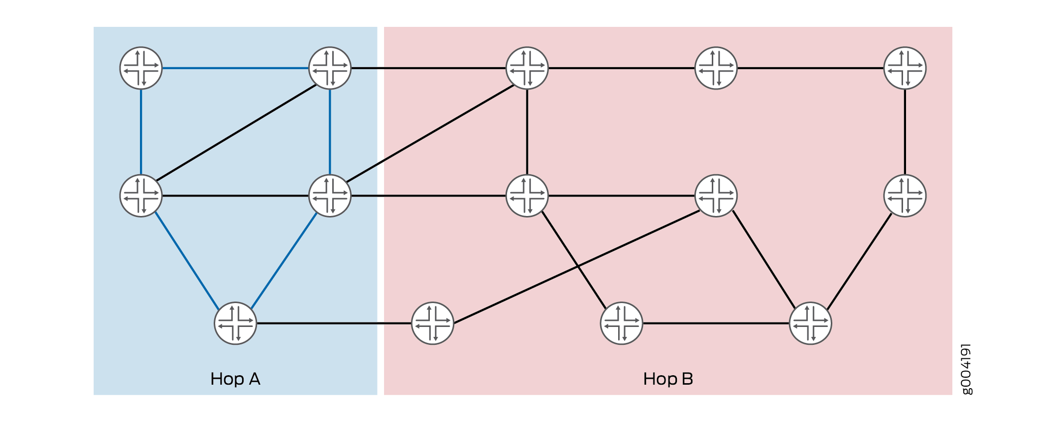
Abstract hop hopA is for low latency AND SRLG west, and abstract hop hopB is for excluding SRLG west. Figure 5 displays the ingress view of these abstract hops.
Using Abstract Hops in Path Constraint
The user associates a unique identifier with each abstract hop definition. This identifier is used for referring to the abstract hop in the path constraint. A sequence of abstract hops can be specified as the path constraint, similar to how real IP hops are used. The path constraint could also be a sequence of abstract hops interleaved by real IP hops.
Using abstract hops or real hops in a path constraint requires more than one Constrained Shortest Path First pass to the destination, typically one pass per hop. When real hops are provided as the path constraint, the constraint computation involves as many passes as the number of hops in the path constraint, where each pass ends on reaching a hop in the constraint list. The starting point for each pass is the destination of the previous pass, with the first pass using the ingress router as the start.
Alternatively, when path constraint uses strict or loose abstract hops, constraint computation comprises passes where each pass processes the subsequent abstract hop in the constraint list. In such a case, more than one node qualifies to be the destination for the pass. The set of nodes is called the viable router set for the pass.
An abstract hop traverses member nodes by using the following:
Links that satisfy the logical combination of defined constituent attributes
Any kind of links
The means of abstract hops traversing the member nodes is controlled by the use of the abstract hop qualifiers—strict, loose, and loose-link—in defining the path constraint. Taking for example, abstract hop hopA is processed differently with different qualifiers:
Strict—After the last processed hop in the constraint list, the path traverses only links or nodes having membership of abstract hop hopA, before reaching a node with hopA’s membership that is a feasible starting point for processing the next abstract hop.
Loose—After the last processed hop in the constraint list, the path can traverse any real nodes that do not have abstract hop membership of hopA, before reaching a node with abstract hop membership hopA, which is a feasible starting point for processing the next abstract hop.
Loose-link—After the last processed hop in the constraint list, the path can traverse any real nodes that do not have abstract hop membership of hopA, before reaching a node with abstract hop membership hopA, which is a feasible starting point for processing the next abstract hop. But the path should have traversed at least one link of abstract hop hopA membership in the course of the same.
In other words, the abstract hop of type loose-link is said to be processed only if any of the viable routers in the constraint is reachable through a link of associated abstract hop membership.
Sample Abstract Hops Specification
Table 2 provides sample use case for using abstract hops in path constraints.
Purpose of Path Constraint |
Abstract Hop Qualifier |
Configuration |
Viable Router Set |
Affinity |
|---|---|---|---|---|
Traverse nodes that are members of hopA taking only links that satisfy hopA. |
Strict |
[edit protocols mpls]
Path path_hopA_s {
    hopA abstract strict;
}
|
All members of abstract hopA. That is, A1, A2…An. |
hopA (pick only links that satisfy abstract hopA). |
Traverse nodes that are members of hopA but not necessarily links that satisfy hopA |
Loose |
[edit protocols mpls]
Path path_hopA_l {
    hopA abstract loose;
}
|
All members of abstract hopA. That is, A1, A2…An. |
None (any kind of links). |
Traverse nodes that are members of hopA by taking at least one link that satisfies hopA. |
Loose-link Note:
The loose-link qualifier is viewed as loose followed by strict for the same abstract hop. In other words, hopA loose-link is the same as hopA loose and hopA strict. |
[edit protocols mpls]
Path path_hopA_ll {
    hopA abstract loose-link;
}
|
In this case, there are two computation passes associated with hopA in the path constraint. The viable router set for both passes is: All members of abstract hopA. That is, A1, A2…An. Note:
During path computation, a router is traversed only once. |
In this case, there are two computation passes associated with hopA in the path constraint. The affinity for the two passes is:
|
Traverse nodes that are members of hopA, taking only links that satisfy hopA, followed by nodes that are members of hopB taking only links that satisfy hopB. |
Strict |
[edit protocols mpls]
Path path_hopA_hopB_s {
    hopA abstract strict;
    hopB abstract strict;
}
|
|
|
Traverse nodes that are members of hopA taking only links that satisfy hopA, followed by nodes that are members of hopB taking any kind of links. |
Strict and loose |
[edit protocols mpls]
Path path_hopA_s_hopB_l {
    hopA abstract strict;
    hopB abstract loose;
}
|
|
|
Traverse nodes that are members of hopA by taking any kinds of links, followed by nodes that are members of hopB taking any kind of links. |
Loose |
[edit protocols mpls]
Path path_hopA_l_hopB_l {
    hopA abstract loose;
    hopB abstract loose;
}
|
|
None (pick any links). |
Traverse nodes that are members of hopA by taking any kinds of links, followed by nodes that are members of hopB taking only links that satisfy hopB. |
Loose and strict |
[edit protocols mpls]
Path path_hopA_l_hopB_s {
    hopA abstract loose;
    hopB abstract strict;
}
|
|
|
Figure 6 displays path constraints for abstract hops hopA, hopB, and hopC with loose, strict, and loose abstract hop qualifiers, respectively.
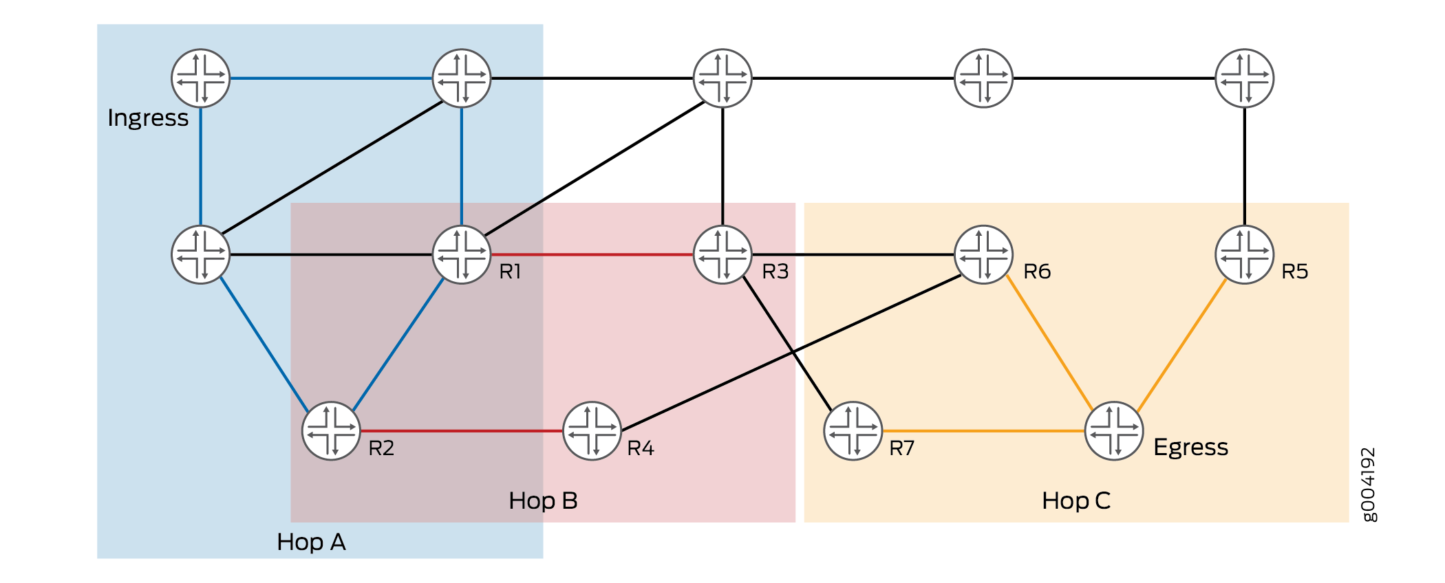
The Constrained Shortest Path First passes for the abstract hops are as follows:
Pass 1 associated with hopA
Viable routers—Routers R1 and R2 (intersection of hopA and hopB, as hopB is a strict abstract hop).
Affinity—None (as hopA is loose).
Pass 2 associated with hopB
Viable routers—Routers R1, R2, R3, and R4
Affinity—Pick only hopB-compliant links (as hopB is a strict abstract hop).
Pass 3 associated with hopC
Viable routers—Routers R5, R6, R7, and the egress router.
Affinity—None (as hopC is a loose abstract hop).
Path Computation and Backtracking
In each Constrained Shortest Path First pass, when the nearest router from a viable router set is reached using links satisfying the affinity figured for the pass, the abstract hop associated with the pass is said to be processed. The viable router thus reached serves as the start for the next constraint pass. If any constraint pass fails, and it is not the one with the ingress router as start router, then the pass is backtracked to the previous pass and the process is repeated.
Sample Backtracking
When a Constrained Shortest Path First pass p (other than the first one) fails, the exit router of the previous pass (p – 1) that served as start for the current pass p is disqualified in the viable router set of the previous pass (p – 1). Then the previous pass (p – 1) is re-executed to find the next best exit router or destination for the pass p – 1 from the viable router set.
The router thus determined serves as the new start router for the pass p. This procedure is repeated as long as there are failures and there are viable routers that are not explored.
The show mpls lsp abstract-hop-computation name lsp-name command provides the various computation
passes involved per LSP and the qualifying exit routers for each pass.
The command output also gives the affinity per pass, and shows the
current start router chosen for the pass. For each viable router,
the state of backtracking is displayed, where it can be either valid
or disqualified.
user@host> show mpls lsp abstract-computation
Path computation using abstract hops for LSP: lsp1
Path type: Primary, Path name: path1

Credibility: 0, Total no of CSPF passes: 2
CSPF pass no: 0 Start address of the pass: 128.102.173.123
Affinity: hopA
CSPF pass no: 1 Start address of the pass: 0.0.0.0
Destination: 128.102.172.157, , State: VALID

Path type: Standby, Path name: path2

Credibility: 0, Total no of CSPF passes: 3
CSPF pass no: 0 Start address of the pass: 128.102.173.123
Destination: 128.102.166.237, , State: VALID
Affinity: hopA
CSPF pass no: 1 Start address of the pass: 128.102.166.237
Destination: 128.102.160.211, , State: VALID
Destination: 128.102.165.5, , State: VALID
Destination: 128.102.166.237, , State: VALID
Destination: 128.102.172.157, , State: VALID
Destination: 128.102.172.196, , State: VALID
Affinity: hopB
CSPF pass no: 2 Start address of the pass: 128.102.172.196
Destination: 128.102.172.157, , State: VALID
The output field Credibility indicates the credibility
associated with the interior gateway protocol in use.
Example: Configuring Abstract Hops for MPLS LSPs
This example shows how to configure abstract hops for MPLS label-switched paths (LSPs). Abstract hops combine the key features of existing traffic engineering constraints that enables the user to specify an order-aware and resilient path constraint for MPLS LSPs.
Requirements
This example uses the following hardware and software components:
Six devices that can be a combination of M Series Multiservice Edge Routers, MX Series 5G Universal Routing Platforms, T Series Core Routers, and PTX Series Packet Transport Routers.
Junos OS Release 17.1 or later running on all the devices.
Before you begin:
Configure the device interfaces.
Configure the device router ID and assign an autonomous system (AS) number.
Configure RSVP on all the devices.
Configure OSPF or any other interior gateway protocol on all the devices.
Configure administrative groups, extended administrative groups, and Shared Risk Link Groups (SRLGs) on all the devices.
Overview
Junos OS Release 17.1 introduces abstract hops, which are user-defined router clusters or groups. Similar to the sequence of real-hop constraints (strict or loose), a sequence of abstract hops can be used for setting up a label-switched path (LSP). A path can use a combination of real and abstract hops as constraints.
An abstract hop is a logical combination of the existing traffic engineering constraints, such as administrative groups, extended administrative groups, and SRLGs, along with the ordering property of real hops. As a result, when a sequence of abstract hops is used in a path constraint, ordering is achieved among the groups of routers that meet a logical combination of link or node attributes called constituent attributes.
To configure abstract hops:
Create constituent lists with constituent traffic engineering attributes by including the
constituent-list list-namestatement at the[edit protocols mpls]hierarchy level.Include the constituent lists in the abstract hop definition at the
[edit protocols mpls abstract-hop abstract-hop-name]hierarchy level.Define path constraints that use abstract hops at the
[edit protocols mpls path path-name]hierarchy level.
Take the following guidelines under consideration when configuring abstract hops for MPLS LSPs:
Abstract hops are supported only in the master routing instance of a device.
IPv6 destinations are not supported in abstract hop constraints (only IPv4 destinations work).
Abstract hops can be strict or loose constraints.
Abstract hops support in Junos OS Release 17.1 is provided only for intra-area MPLS LSPs and not for inter-domain, or inter-area LSPs.
Abstract hop constraints is enabled for regular point-to-point LSPs only. Other types of MPLS LSPs, such as point-to-multipoint LSPs, externally controlled bidirectional LSPs, dynamic container LSPs, RSVP automesh LSPs, and inter-area LSPs are not supported with abstract hops configuration.
Abstract hops do not enable computation of overall shortest path for LSPs.
An abstract hop must not be referred to more than once in the same path constraint.
Abstract hop constraint specifications do not affect the support for Graceful Routing Engine switchover (GRES), unified in-service software upgrade (ISSU), and nonstop routing (NSR).
Abstract hop constraint specifications do not affect overall network performance. However, the time taken for constrained shortest path first computation increases with abstract hop configuration. The setup time for an abstract hop LSP is more than the time taken to set up an LSP without abstract hop configuration.
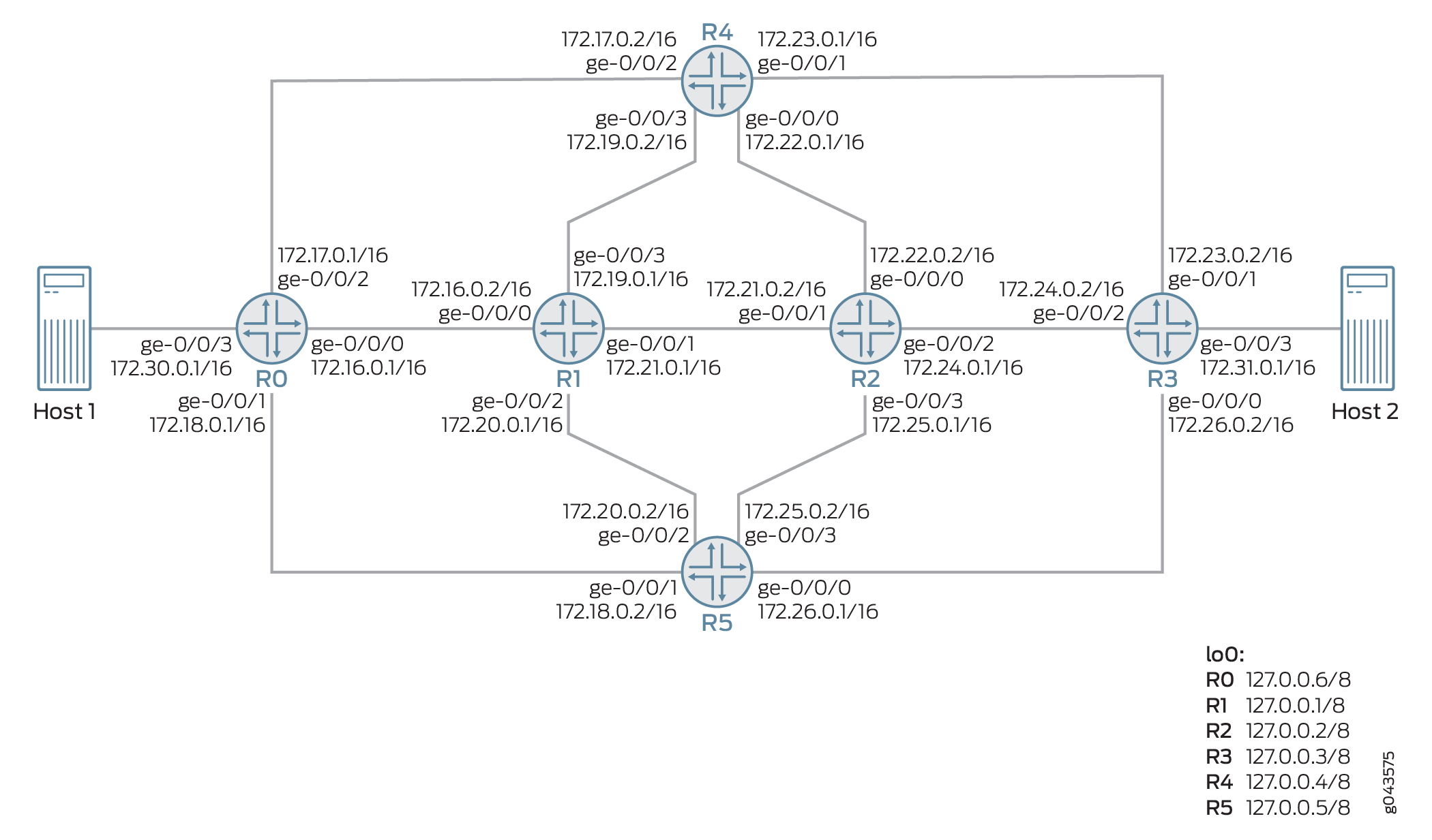
Topology
Figure 7 illustrates a sample network topology configured with abstract hops. Devices R0 and R3 are each connected to hosts (Host 1 and Host 2). Devices R4 and R5 are each connected to Devices R0, R1, R2, and R3. Devices R1 and R2 are also directly connected to each other.
Devices R0 and R3 are configured under the same autonomous system—AS 64496. An MPLS LSP is configured from Device R0 through Device R3 with one primary path and two secondary paths (standby and nonstandby secondary paths).
Four constituent lists—c1, c2, c3, and c4—are created using three SRLGs (g1, g2, and g3), three administrative groups (green, blue, and red), and one extended administrative group (gold). Three abstract hops (ah1, ah2, and ah3) are defined using the configured constituent lists, and are specified as path constraints. Abstract hop ah1 is specified as constraint for the primary path, while abstract hops ah2 and ah3 are specified as constraints for the secondary standby path and the secondary nonstandby path, respectively.
Configuration
CLI Quick Configuration
To quickly configure this example, copy the
following commands, paste them into a text file, remove any line breaks,
change any details necessary to match your network configuration,
copy and paste the commands into the CLI at the [edit] hierarchy
level, and then enter commit from configuration mode.
Device R0
set chassis network-services ip
set interfaces ge-0/0/0 unit 0 family inet address 172.16.0.1/16
set interfaces ge-0/0/0 unit 0 family mpls
set interfaces ge-0/0/1 unit 0 family inet address 172.18.0.1/16
set interfaces ge-0/0/1 unit 0 family mpls
set interfaces ge-0/0/2 unit 0 family inet address 172.17.0.1/16
set interfaces ge-0/0/2 unit 0 family mpls
set interfaces ge-0/0/3 unit 0 family inet address 172.30.0.1/16
set interfaces lo0 unit 0 family inet address 127.0.0.6/8
set routing-options srlg g1 srlg-value 100
set routing-options srlg g1 srlg-cost 1000
set routing-options srlg g2 srlg-value 200
set routing-options srlg g2 srlg-cost 2000
set routing-options srlg g3 srlg-value 300
set routing-options srlg g3 srlg-cost 3000
set routing-options administrative-groups-extended-range minimum 50000
set routing-options administrative-groups-extended-range maximum 60000
set routing-options administrative-groups-extended gold group-value 50000
set routing-options router-id 127.0.0.6
set routing-options autonomous-system 64496
set routing-options forwarding-table export test
set protocols rsvp interface all aggregate
set protocols rsvp interface fxp0.0 disable
set protocols rsvp interface ge-0/0/0.0 bandwidth 80m
set protocols rsvp interface ge-0/0/2.0 bandwidth 200m
set protocols rsvp interface ge-0/0/1.0 bandwidth 500m
set protocols mpls administrative-groups green 0
set protocols mpls administrative-groups blue 1
set protocols mpls administrative-groups red 2
set protocols mpls label-switched-path R0-R31 to 127.0.0.3
set protocols mpls label-switched-path R0-R31 primary prim
set protocols mpls label-switched-path R0-R31 secondary stdby standby
set protocols mpls label-switched-path R0-R31 secondary nonstdby
set protocols mpls path path_primary 172.16.0.2 strict
set protocols mpls path path_primary 172.21.0.2 strict
set protocols mpls path path_primary 172.24.0.2 strict
set protocols mpls path path_ter_nonstdby 172.18.0.1 strict
set protocols mpls path path_ter_nonstdby 172.26.0.2 strict
set protocols mpls path path_sec_stdby 172.17.0.2 strict
set protocols mpls path path_sec_stdby 172.23.0.2 strict
set protocols mpls path prim ah1 abstract
set protocols mpls path prim ah1 strict
set protocols mpls path stdby ah2 abstract
set protocols mpls path stdby ah2 strict
set protocols mpls path nonstdby ah3 abstract
set protocols mpls path nonstdby ah3 strict
set protocols mpls constituent-list c1 srlg g1
set protocols mpls constituent-list c1 administrative-group green
set protocols mpls constituent-list c2 administrative-group green
set protocols mpls constituent-list c2 administrative-group-extended gold
set protocols mpls constituent-list c3 srlg g2
set protocols mpls constituent-list c3 administrative-group red
set protocols mpls constituent-list c3 administrative-group-extended gold
set protocols mpls constituent-list c4 srlg g3
set protocols mpls constituent-list c4 administrative-group blue
set protocols mpls constituent-list c4 administrative-group-extended gold
set protocols mpls abstract-hop ah1 operator AND
set protocols mpls abstract-hop ah1 constituent-list c1 include-all-list
set protocols mpls abstract-hop ah1 constituent-list c2 include-all-list
set protocols mpls abstract-hop ah2 operator AND
set protocols mpls abstract-hop ah2 constituent-list c3 include-all-list
set protocols mpls abstract-hop ah3 operator AND
set protocols mpls abstract-hop ah3 constituent-list c4 include-all-list
set protocols mpls interface all
set protocols mpls interface fxp0.0 disable
set protocols mpls interface ge-0/0/0.0 srlg g1
set protocols mpls interface ge-0/0/0.0 administrative-group green
set protocols mpls interface ge-0/0/0.0 administrative-group-extended gold
set protocols mpls interface ge-0/0/2.0 srlg g2
set protocols mpls interface ge-0/0/2.0 administrative-group red
set protocols mpls interface ge-0/0/2.0 administrative-group-extended gold
set protocols mpls interface ge-0/0/1.0 srlg g3
set protocols mpls interface ge-0/0/1.0 administrative-group blue
set protocols mpls interface ge-0/0/1.0 administrative-group-extended gold
set protocols ospf traffic-engineering
set protocols ospf area 0.0.0.0 interface all
set protocols ospf area 0.0.0.0 interface fxp0.0 disable
set policy-options policy-statement test then load-balance per-packet
Device R1
set interfaces ge-0/0/0 unit 0 family inet address 172.16.0.2/16
set interfaces ge-0/0/0 unit 0 family mpls
set interfaces ge-0/0/1 unit 0 family inet address 172.21.0.1/16
set interfaces ge-0/0/1 unit 0 family mpls
set interfaces ge-0/0/2 unit 0 family inet address 172.20.0.1/16
set interfaces ge-0/0/2 unit 0 family mpls
set interfaces ge-0/0/3 unit 0 family inet address 172.19.0.1/16
set interfaces ge-0/0/3 unit 0 family mpls
set interfaces lo0 unit 0 family inet address 127.0.0.1/8
set routing-options srlg g1 srlg-value 100
set routing-options srlg g1 srlg-cost 1000
set routing-options srlg g2 srlg-value 200
set routing-options srlg g2 srlg-cost 2000
set routing-options srlg g3 srlg-value 300
set routing-options srlg g3 srlg-cost 3000
set routing-options administrative-groups-extended-range minimum 50000
set routing-options administrative-groups-extended-range maximum 60000
set routing-options administrative-groups-extended gold group-value 50000
set routing-options router-id 127.0.0.1
set protocols rsvp interface fxp0.0 disable
set protocols mpls administrative-groups green 0
set protocols mpls administrative-groups blue 1
set protocols mpls administrative-groups red 2
set protocols mpls interface all
set protocols mpls interface fxp0.0 disable
set protocols mpls interface ge-0/0/0.0 srlg g1
set protocols mpls interface ge-0/0/0.0 administrative-group green
set protocols mpls interface ge-0/0/0.0 administrative-group-extended gold
set protocols mpls interface ge-0/0/1.0 srlg g1
set protocols mpls interface ge-0/0/1.0 administrative-group green
set protocols mpls interface ge-0/0/1.0 administrative-group-extended gold
set protocols ospf traffic-engineering
set protocols ospf area 0.0.0.0 interface all
set protocols ospf area 0.0.0.0 interface fxp0.0 disable
Device R2
set interfaces ge-0/0/0 unit 0 family inet address 172.22.0.2/16
set interfaces ge-0/0/0 unit 0 family mpls
set interfaces ge-0/0/1 unit 0 family inet address 172.21.0.2/16
set interfaces ge-0/0/1 unit 0 family mpls
set interfaces ge-0/0/2 unit 0 family inet address 172.24.0.1/16
set interfaces ge-0/0/2 unit 0 family mpls
set interfaces ge-0/0/3 unit 0 family inet address 172.25.0.1/16
set interfaces ge-0/0/3 unit 0 family mpls
set interfaces lo0 unit 0 family inet address 127.0.0.2/8
set routing-options srlg g1 srlg-value 100
set routing-options srlg g1 srlg-cost 1000
set routing-options srlg g2 srlg-value 200
set routing-options srlg g2 srlg-cost 2000
set routing-options srlg g3 srlg-value 300
set routing-options srlg g3 srlg-cost 3000
set routing-options administrative-groups-extended-range minimum 50000
set routing-options administrative-groups-extended-range maximum 60000
set routing-options administrative-groups-extended gold group-value 50000
set routing-options router-id 127.0.0.2
set protocols rsvp interface all aggregate
set protocols rsvp interface fxp0.0 disable
set protocols mpls administrative-groups green 0
set protocols mpls administrative-groups blue 1
set protocols mpls administrative-groups red 2
set protocols mpls interface all
set protocols mpls interface fxp0.0 disable
set protocols mpls interface ge-0/0/1.0 srlg g1
set protocols mpls interface ge-0/0/1.0 administrative-group green
set protocols mpls interface ge-0/0/1.0 administrative-group-extended gold
set protocols mpls interface ge-0/0/2.0 srlg g1
set protocols mpls interface ge-0/0/2.0 administrative-group green
set protocols mpls interface ge-0/0/2.0 administrative-group-extended gold
set protocols ospf traffic-engineering
set protocols ospf area 0.0.0.0 interface all
set protocols ospf area 0.0.0.0 interface fxp0.0 disable
Device R3
set interfaces ge-0/0/0 unit 0 family inet address 172.26.0.2/16
set interfaces ge-0/0/0 unit 0 family mpls
set interfaces ge-0/0/1 unit 0 family inet address 172.23.0.2/16
set interfaces ge-0/0/1 unit 0 family mpls
set interfaces ge-0/0/2 unit 0 family inet address 172.24.0.2/16
set interfaces ge-0/0/2 unit 0 family mpls
set interfaces ge-0/0/3 unit 0 family inet address 172.31.0.1/16
set interfaces lo0 unit 0 family inet address 127.0.0.3/8
set routing-options srlg g1 srlg-value 100
set routing-options srlg g1 srlg-cost 1000
set routing-options srlg g2 srlg-value 200
set routing-options srlg g2 srlg-cost 2000
set routing-options srlg g3 srlg-value 300
set routing-options srlg g3 srlg-cost 3000
set routing-options administrative-groups-extended-range minimum 50000
set routing-options administrative-groups-extended-range maximum 60000
set routing-options administrative-groups-extended gold group-value 50000
set routing-options router-id 127.0.0.3
set routing-options autonomous-system 64496
set protocols rsvp interface all aggregate
set protocols rsvp interface fxp0.0 disable
set protocols mpls administrative-groups green 0
set protocols mpls administrative-groups blue 1
set protocols mpls administrative-groups red 2
set protocols mpls interface all
set protocols mpls interface fxp0.0 disable
set protocols mpls interface ge-0/0/2.0 srlg g1
set protocols mpls interface ge-0/0/2.0 administrative-group green
set protocols mpls interface ge-0/0/2.0 administrative-group-extended gold
set protocols mpls interface ge-0/0/1.0 srlg g2
set protocols mpls interface ge-0/0/1.0 administrative-group red
set protocols mpls interface ge-0/0/1.0 administrative-group-extended gold
set protocols mpls interface ge-0/0/0.0 srlg g3
set protocols mpls interface ge-0/0/0.0 administrative-group blue
set protocols mpls interface ge-0/0/0.0 administrative-group-extended gold
set protocols ospf traffic-engineering
set protocols ospf area 0.0.0.0 interface all
set protocols ospf area 0.0.0.0 interface fxp0.0 disable
Device R4
set interfaces ge-0/0/0 unit 0 family inet address 172.22.0.1/16
set interfaces ge-0/0/0 unit 0 family mpls
set interfaces ge-0/0/1 unit 0 family inet address 172.23.0.1/16
set interfaces ge-0/0/1 unit 0 family mpls
set interfaces ge-0/0/2 unit 0 family inet address 172.17.0.2/16
set interfaces ge-0/0/2 unit 0 family mpls
set interfaces ge-0/0/3 unit 0 family inet address 172.19.0.2/16
set interfaces ge-0/0/3 unit 0 family mpls
set interfaces lo0 unit 0 family inet address 127.0.0.4/32
set routing-options srlg g1 srlg-value 100
set routing-options srlg g1 srlg-cost 1000
set routing-options srlg g2 srlg-value 200
set routing-options srlg g2 srlg-cost 2000
set routing-options srlg g3 srlg-value 300
set routing-options srlg g3 srlg-cost 3000
set routing-options administrative-groups-extended-range minimum 50000
set routing-options administrative-groups-extended-range maximum 60000
set routing-options administrative-groups-extended gold group-value 50000
set routing-options router-id 127.0.0.4
set protocols rsvp interface all aggregate
set protocols rsvp interface fxp0.0 disable
set protocols mpls administrative-groups green 0
set protocols mpls administrative-groups blue 1
set protocols mpls administrative-groups red 2
set protocols mpls icmp-tunneling
set protocols mpls interface all
set protocols mpls interface fxp0.0 disable
set protocols mpls interface ge-0/0/2.0 srlg g2
set protocols mpls interface ge-0/0/2.0 administrative-group red
set protocols mpls interface ge-0/0/2.0 administrative-group-extended gold
set protocols mpls interface ge-0/0/1.0 srlg g2
set protocols mpls interface ge-0/0/1.0 administrative-group red
set protocols mpls interface ge-0/0/1.0 administrative-group-extended gold
set protocols ospf traffic-engineering
set protocols ospf area 0.0.0.0 interface all
set protocols ospf area 0.0.0.0 interface fxp0.0 disable
Device R5
set interfaces ge-0/0/0 unit 0 family inet address 172.26.0.1/16
set interfaces ge-0/0/0 unit 0 family mpls
set interfaces ge-0/0/1 unit 0 family inet address 172.18.0.2/16
set interfaces ge-0/0/1 unit 0 family mpls
set interfaces ge-0/0/2 unit 0 family inet address 172.20.0.2/24
set interfaces ge-0/0/2 unit 0 family mpls
set interfaces ge-0/0/3 unit 0 family inet address 172.25.0.2/16
set interfaces ge-0/0/3 unit 0 family mpls
set interfaces lo0 unit 0 family inet address 127.0.0.5/8
set routing-options srlg g1 srlg-value 100
set routing-options srlg g1 srlg-cost 1000
set routing-options srlg g2 srlg-value 200
set routing-options srlg g2 srlg-cost 2000
set routing-options srlg g3 srlg-value 300
set routing-options srlg g3 srlg-cost 3000
set routing-options administrative-groups-extended-range minimum 50000
set routing-options administrative-groups-extended-range maximum 60000
set routing-options administrative-groups-extended gold group-value 50000
set routing-options router-id 127.0.0.5
set protocols rsvp interface all aggregate
set protocols rsvp interface fxp0.0 disable
set protocols mpls administrative-groups green 0
set protocols mpls administrative-groups blue 1
set protocols mpls administrative-groups red 2
set protocols mpls interface all
set protocols mpls interface fxp0.0 disable
set protocols mpls interface ge-0/0/1.0 srlg g3
set protocols mpls interface ge-0/0/1.0 administrative-group blue
set protocols mpls interface ge-0/0/1.0 administrative-group-extended gold
set protocols mpls interface ge-0/0/0.0 srlg g3
set protocols mpls interface ge-0/0/0.0 administrative-group blue
set protocols mpls interface ge-0/0/0.0 administrative-group-extended gold
set protocols ospf traffic-engineering
set protocols ospf area 0.0.0.0 interface all
set protocols ospf area 0.0.0.0 interface fxp0.0 disable
Procedure
Step-by-Step Procedure
The following example requires that you navigate various levels in the configuration hierarchy. For information about navigating the CLI, see Using the CLI Editor in Configuration Mode in the CLI User Guide.
To configure Device R0:
Enable enhanced IP network services on Device R0.
[edit chassis]
user@R0# set network-services ip
Configure the interfaces on Device R0, including the loopback interface.
[edit interfaces]
user@R0# set ge-0/0/0 unit 0 family inet address 172.16.0.1/16
user@R0# set ge-0/0/0 unit 0 family mpls
user@R0# set ge-0/0/1 unit 0 family inet address 172.18.0.1/16
user@R0# set ge-0/0/1 unit 0 family mpls
user@R0# set ge-0/0/2 unit 0 family inet address 172.17.0.1/16
user@R0# set ge-0/0/2 unit 0 family mpls
user@R0# set ge-0/0/3 unit 0 family inet address 172.30.0.1/16
user@R0# set lo0 unit 0 family inet address 127.0.0.6/8
Assign the router ID and autonomous system number for Device R0.
[edit routing-options]
user@R0# set router-id 127.0.0.6
user@R0# set autonomous-system 64496
Configure the SRLG definitions.
[edit routing-options]
user@R0# set srlg g1 srlg-value 100
user@R0# set srlg g1 srlg-cost 1000
user@R0# set srlg g2 srlg-value 200
user@R0# set srlg g2 srlg-cost 2000
user@R0# set srlg g3 srlg-value 300
user@R0# set srlg g3 srlg-cost 3000
Configure the extended administrative group definitions.
[edit routing-options]
user@R0# set administrative-groups-extended-range minimum 50000
user@R0# set administrative-groups-extended-range maximum 60000
user@R0# set administrative-groups-extended gold group-value 50000
Configure the administrative group definitions.
[edit protocols]
user@R0# set mpls administrative-groups green 0
user@R0# set mpls administrative-groups blue 1
user@R0# set mpls administrative-groups red 2
Configure MPLS on all the interfaces of Device R0, excluding the management interface.
[edit protocols]
user@R0# set mpls interface all
user@R0# set mpls interface fxp0.0 disable
Assign the interfaces of Device R0 with the configured traffic engineering attributes.
[edit protocols]
user@R0# set mpls interface ge-0/0/0.0 srlg g1
user@R0# set mpls interface ge-0/0/0.0 administrative-group green
user@R0# set mpls interface ge-0/0/0.0 administrative-group-extended gold
user@R0# set mpls interface ge-0/0/2.0 srlg g2
user@R0# set mpls interface ge-0/0/2.0 administrative-group red
user@R0# set mpls interface ge-0/0/2.0 administrative-group-extended gold
user@R0# set mpls interface ge-0/0/1.0 srlg g3
user@R0# set mpls interface ge-0/0/1.0 administrative-group blue
user@R0# set mpls interface ge-0/0/1.0 administrative-group-extended gold
Configure an LSP connecting Device R0 with Device R3, and assign primary and secondary path attributes to the LSP.
[edit protocols]
user@R0# set mpls label-switched-path R0-R31 to 127.0.0.3
user@R0# set mpls label-switched-path R0-R31 primary prim
user@R0# set mpls label-switched-path R0-R31 secondary stdby standby
user@R0# set mpls label-switched-path R0-R31 secondary nonstdby
Define the primary and secondary paths for the R0-R31 LSP.
[edit protocols]
user@R0# set mpls path path_primary 172.16.0.2 strict
user@R0# set mpls path path_primary 172.21.0.2 strict
user@R0# set mpls path path_primary 172.24.0.2 strict
user@R0# set mpls path path_ter_nonstdby 172.18.0.1 strict
user@R0# set mpls path path_ter_nonstdby 172.26.0.2 strict
user@R0# set mpls path path_sec_stdby 172.17.0.2 strict
user@R0# set mpls path path_sec_stdby 172.23.0.2 strict
Create constituent lists with constituent traffic engineering attributes for abstract-hop definitions.
[edit protocols]
user@R0# set mpls constituent-list c1 srlg g1
user@R0# set mpls constituent-list c1 administrative-group green
user@R0# set mpls constituent-list c2 administrative-group green
user@R0# set mpls constituent-list c2 administrative-group-extended gold
user@R0# set mpls constituent-list c3 srlg g2
user@R0# set mpls constituent-list c3 administrative-group red
user@R0# set mpls constituent-list c3 administrative-group-extended gold
user@R0# set mpls constituent-list c4 srlg g3
user@R0# set mpls constituent-list c4 administrative-group blue
user@R0# set mpls constituent-list c4 administrative-group-extended gold
Define abstract hops by assigning the configured constituent lists and respective operators.
[edit protocols]
user@R0# set mpls abstract-hop ah1 operator AND
user@R0# set mpls abstract-hop ah1 constituent-list c1 include-all-list
user@R0# set mpls abstract-hop ah1 constituent-list c2 include-all-list
user@R0# set mpls abstract-hop ah2 operator AND
user@R0# set mpls abstract-hop ah2 constituent-list c3 include-all-list
user@R0# set mpls abstract-hop ah3 operator AND
user@R0# set mpls abstract-hop ah3 constituent-list c4 include-all-list
Define constraints for the configured paths by including abstract hop definitions.
[edit protocols]
user@R0# set mpls path prim ah1 abstract
user@R0# set mpls path prim ah1 strict
user@R0# set mpls path stdby ah2 abstract
user@R0# set mpls path stdby ah2 strict
user@R0# set mpls path nonstdby ah3 abstract
user@R0# set mpls path nonstdby ah3 strict
Configure RSVP on Device R0. Enable RSVP on all the interfaces of Device R0, excluding the management interface and interface connecting to Host1, and assign bandwidth values.
[edit protocols]
user@R0# set rsvp interface all aggregate
user@R0# set rsvp interface fxp0.0 disable
user@R0# set rsvp interface ge-0/0/0.0 bandwidth 80m
user@R0# set rsvp interface ge-0/0/2.0 bandwidth 200m
user@R0# set rsvp interface ge-0/0/1.0 bandwidth 500m
Configure OSPF on all the interfaces of Device R0, excluding the management interface, and assign traffic engineering capabilities.
[edit protocols]
user@R0# set ospf traffic-engineering
user@R0# set ospf area 0.0.0.0 interface all
user@R0# set ospf area 0.0.0.0 interface fxp0.0 disable
Configure a policy on Device R0 to enable load balancing on a per-packet basis.
[edit policy-options]
user@R0# set forwarding-table export test
Export the load-balancing policy to the forwarding table.
[edit policy-options]
user@R0# set policy-statement test then load-balance per-packet
Results
From configuration mode, confirm your configuration
by entering the show chassis, show interfaces, show routing-options, show protocols, and show policy-options commands. If the output does not display
the intended configuration, repeat the instructions in this example
to correct the configuration.
user@R0# show chassis
network-services ip;
user@R0# show interfaces
ge-0/0/0 {
    unit 0 {
        family inet {
            address 172.16.0.1/16;
        }
        family mpls;
    }
}
ge-0/0/1 {
    unit 0 {
        family inet {
            address 172.18.0.1/16;
        }
        family mpls;
    }
}
ge-0/0/2 {
    unit 0 {
        family inet {
            address 172.17.0.1/16;
        }
        family mpls;
    }
}
ge-0/0/3 {
    unit 0 {
        family inet {
            address 172.30.0.1/16;
        }
    }
}
lo0 {
    unit 0 {
        family inet {
            address 127.0.0.6/8;
        }
    }
}
user@R0# show routing-options
srlg {
    g1 {
        srlg-value 100;
        srlg-cost 1000;
    }
    g2 {
        srlg-value 200;
        srlg-cost 2000;
    }
    g3 {
        srlg-value 300;
        srlg-cost 3000;
    }
}
administrative-groups-extended-range {
    minimum 50000;
    maximum 60000;
}
administrative-groups-extended {
    gold group-value 50000;
}
user@R0# show protocols
rsvp {
    interface all;
    interface fxp0.0 {
        disable;
    }
    interface ge-0/0/0.0 {
        bandwidth 80m;
    }
    interface ge-0/0/2.0 {
        bandwidth 200m;
    }
    interface ge-0/0/1.0 {
        bandwidth 500m;
    }
}
mpls {
    administrative-groups {
        green 0;
        blue 1;
        red 2;
    }
    label-switched-path R0-R31 {
        to 127.0.0.3;
        adaptive;
        auto-bandwidth {
            adjust-interval 300;
            adjust-threshold 5;
            minimum-bandwidth 10m;
            maximum-bandwidth 1g;
        }
        primary prim;
        secondary stdby {
            standby;
        }
        secondary nonstdby;
    }
    path path_primary {
        172.16.0.2 strict;
        172.21.0.2 strict;
        172.24.0.2 strict;
    }
    path path_ter_nonstdby {
        172.18.0.1 strict;
        172.26.0.2 strict;
    }
    path path_sec_stdby {
        172.17.0.2 strict;
        172.23.0.2 strict;
    }
    path prim {
        ah1 abstract strict;
    }
    path stdby {
        ah2 abstract strict;
    }
    path nonstdby {
        ah3 abstract strict;
    }
    constituent-list c1 {
        srlg g1;
        administrative-group green;
    }
    constituent-list c2 {
        administrative-group green;
        administrative-group-extended gold;
    }
    constituent-list c3 {
        srlg g2;
        administrative-group red;
        administrative-group-extended gold;
    }
    constituent-list c4 {
        srlg g3;
        administrative-group blue;
        administrative-group-extended gold;
    }
    abstract-hop ah1 {
        operator AND;
        constituent-list {
            c1 include-all-list;
            c2 include-all-list;
        }
    }
    abstract-hop ah2 {
        operator AND;
        constituent-list {
            c3 include-all-list;
        }
    }
    abstract-hop ah3 {
        operator AND;
        constituent-list {
            c4 include-all-list;
        }
    }
    interface all;
    interface fxp0.0 {
        disable;
    }
    interface ge-0/0/0.0 {
        srlg g1;
        administrative-group green;
        administrative-group-extended gold;
    }
    interface ge-0/0/2.0 {
        srlg g2;
        administrative-group red;
        administrative-group-extended gold;
    }
    interface ge-0/0/1.0 {
        srlg g3;
        administrative-group blue;
        administrative-group-extended gold;
    }
}
ospf {
    traffic-engineering;
    area 0.0.0.0 {
        interface all;
        interface fxp0.0 {
            disable;
        }
    }
}
user@R0# show policy-options
policy-statement test {
    then {
        load-balance per-packet;
    }
}
Verification
Confirm that the configuration is working properly.
Verifying Abstract Hop Configuration
Purpose
Verify the members of the abstract hop definition on
Device R0 by issuing the show mpls abstract-hop-membership command, which displays the abstract hop membership tables.
Action
From operational mode, run the show mpls abstract-hop-membership command.
user@R0> show mpls abstract-hop-membership
Abstract hop: ah1
   Credibility: 0
Address: 127.0.0.6
Address: 127.0.0.1
Address: 127.0.0.2
Address: 127.0.0.3

Abstract hop: ah2
   Credibility: 0
Address: 127.0.0.6
Address: 127.0.0.3
Address: 127.0.0.4

Abstract hop: ah3
   Credibility: 0
Address: 127.0.0.6
Address: 127.0.0.3
Address: 127.0.0.5
Meaning
The show mpls abstract-hop-membership command
output provides the abstract hop to traffic engineering database node
mapping. The Credibility field displays the credibility
value associated with the interior gateway protocol in use (OSPF).
Verifying Abstract Hop Path Computation
Purpose
Verify the abstract computation preprocessing for LSPs
on Device R0 by issuing the show mpls lsp abstract-computation command.
Action
From operational mode, run the show mpls lsp abstract-computation command.
user@R0> show mpls lsp abstract-computation
Path computation using abstract hops for LSP: R0-R31
   Path type: Primary, Path name: prim

   Credibility: 0, Total no of CSPF passes: 2
     CSPF pass no: 0
      Start address of the pass: 127.0.0.6
       Destination: 127.0.0.1, State: VALID
       Destination: 127.0.0.2, State: VALID
       Destination: 127.0.0.3, State: VALID
       Affinity: ah1
     CSPF pass no: 1
      Start address of the pass: 127.0.0.1
       Destination: 127.0.0.3, State: VALID
   Path type: Secondary, Path name: nonstdby
   Path type: Standby, Path name: stdby

   Credibility: 0, Total no of CSPF passes: 2
     CSPF pass no: 0
      Start address of the pass: 127.0.0.6
       Destination: 127.0.0.3, State: VALID
       Destination: 127.0.0.4, State: VALID
       Affinity: ah2
     CSPF pass no: 1
      Start address of the pass: 127.0.0.4
       Destination: 127.0.0.3, State: VALID
Meaning
The show mpls lsp abstract-hop-computation command output provides the various computation passes involved
per LSP, and the qualifying exit devces for each pass. The command
output also gives the affinity per pass, and shows the current start
device chosen for the pass. For each viable router (device), the state
of backtracking is displayed, where it can either be valid or disqualified.
The Credibility field indicates the credibility value
associated with the interior gateway protocol in use (OSPF).
Configuring the Maximum Number of MPLS Labels
For interfaces that you configure for MPLS applications, you can set the maximum number of labels upon which MPLS can operate.
By default, the maximum number of labels is three. You can change the maximum to four labels or five labels for applications that require four or five labels.
Starting in Junos OS
Release 19.1R1, the maximum number of labels that can be pushed by
the egress Packet Forwarding Engine (PFE) can be leveraged, wherein
the number of labels that can be pushed for an MPLS next hop is the
number of labels the device is capable of pushing, or the maximum-labels configured under family mpls of the outgoing interface,
whichever is smaller. This support is enabled on MX Series routers
with MPC and MIC interfaces, and PTX Series routers with third-generation
FPCs.
On PTX Series routers, the maximum number of labels that can be pushed by the ingress PFE is 4 and egress PFE is 8.
The increased label push capability is useful for features, such as segment routing traffic-engineering LSPs and RSVP-TE pop-and-forward LSPs. All existing functionality of applications using MPLS next hops continue to work with the increased label push capability. This includes:
All OAM utilities, such as lsping, traceroute, and BFD for MPLS LSPs.
Monitoring utilities, such as lspmon, and LM DM for MPLS LSPs.
The show route table and show route forwarding-table command outputs are enhanced to display up to 16 labels per next
hop component.
For example:
user@host> show route table inet.3

inet.3: 1 destinations, 1 routes (1 active, 0 holddown, 0 hidden)
+ = Active Route, - = Last Active, * = Both

11.0.0.17/32       *[SPRING-TE/8] 00:02:16, metric 1
                    > to 192.1.2.2 via ge-0/0/2.0, Push 1000115, Push 1000114, Push 1000113, Push 1000112, Push 1000111, Push 1000110, Push 1000109, Push 1000108, Push 1000107, Push 1000106, Push 1000105, Push 1000104, Push 1000103, Push 1000102, Push 1000101(top)
                      to 192.1.3.2 via ge-0/0/4.0, Push 1000115, Push 1000114, Push 1000113, Push 1000112, Push 1000111, Push 1000110, Push 1000109, Push 1000108, Push 1000107, Push 1000106, Push 1000105, Push 1000104, Push 1000103, Push 1000102, Push 1000101(top)
When the maximum number of MPLS labels of an interface is modified, the MPLS interface is bounced. All LDP and RSVP sessions on that interface are restarted, resulting in all LSPs over that interface to flap.
For example, suppose you configure a two-tier carrier-of-carriers VPN service for customers who provide VPN service. A carrier-of-carrier VPN is a two-tiered relationship between a provider carrier (Tier 1 ISP) and a customer carrier (Tier 2 ISP). In a carrier-of-carrier VPN, the provider carrier provides a VPN backbone network for the customer carrier. The customer carrier in turn provides Layer 3 VPN service to its end customers. The customer carrier sends labeled traffic to the provider carrier to deliver it to the next hop on the other side of the provider carrier’s network. This scenario requires a three-label stack: one label for the provider carrier VPN, another label for the customer carrier VPN, and a third label for the transport route.
If you add fast reroute service, the PE routers in the provider carrier’s network must be configured to support a fourth label (the reroute label). If the customer carrier is using LDP as its signaling protocol and the provider carrier is using RSVP, the provider carrier must support LDP over RSVP tunnel service. This additional service requires an additional label, for a total of five labels.
To the customer carrier, the router it uses to connect to the provider carrier’s VPN is a PE router. However, the provider carrier views this device as a CE router.
Table 3 summarizes the label requirements.
Number of Labels Required |
Scenarios |
|---|---|
3 |
Carrier-of-carriers VPN or a VPN with two labels and fast reroute |
4 |
Combination of carrier-of-carriers and fast reroute |
5 |
Carrier-of-carriers with fast reroute and the customer carrier running LDP, with the provider carrier running RSVP |
To configure and monitor the maximum number of labels:
Configuring MPLS to Pop the Label on the Ultimate-Hop Router
You can control the label value advertised on the egress router of a label-switched path (LSP). The default advertised label is label 3 (Implicit Null Label). If label 3 is advertised, the penultimate-hop router removes the label and sends the packet to the egress router. By enabling ultimate-hop popping, label 0 (IPv4 Explicit Null Label) is advertised. Ultimate-hop popping ensures that any packets traversing an MPLS network include a label.
Juniper Networks routers queue packets based on the incoming label. Routers from other vendors might queue packets differently. Keep this in mind when working with networks containing routers from multiple vendors.
To configure MPLS to pop the label on the ultimate-hop router,
include the explicit-null statement:
explicit-null;
You can configure this statement at the following hierarchy levels:
[edit protocols mpls][edit logical-systems logical-system-name protocols mpls]
Advertising Explicit Null Labels to BGP Peers
For the IPv4 (inet) family only, BGP peers in a routing
group can send an explicit NULL label for a set of connected routes
(direct and loopback routes) for the inet labeled-unicast and inet6
labeled-unicast NLRI. By default, peers advertise label 3 (implicit
NULL). If the explicit-null statement is enabled, peers
advertise label 0 (explicit NULL). The explicit NULL labels ensures
that labels are always present on packets traversing an MPLS network.
If the implicit NULL label is used. the penultimate hop router removes
the label and sends the packet as a plain IP packet to the egress
router. This might cause issues in queuing the packet properly on
the penultimate hop router if the penultimate hop is another vendor’s
router. Some other vendors queue packets based on the CoS bits in
the outgoing label rather than the incoming label.
To advertise an explicit null label, include the following statements in the configuration:
family inet {
    labeled-unicast {
        aggregate-label {
            community community-name:
        }
        explicit-null {
            connected-only;
        }
    }
}
For a list of hierarchy levels at which you can include this statement, see the statement summary section for this statement.
The connected-only statement is required to advertise
explicit null labels.
To verify that the explicit NULL label is being advertised for
connected routes, use the show route advertising-protocol bgp neighbor-address command.
Understanding MPLS Label Operations on EX Series Switches
In the traditional packet-forwarding paradigm, as a packet travels from one switch to the next, an independent forwarding decision is made at each hop. The IP network header is analyzed and the next hop is chosen based on this analysis and on the information in the routing table. In an MPLS environment, the analysis of the packet header is made only once, when a packet enters the MPLS tunnel (that is, the path used for MPLS traffic).
When an IP packet enters a label-switched path (LSP), the ingress provider edge (PE) switch examines the packet and assigns it a label based on its destination, placing the label in the packet’s header. The label transforms the packet from one that is forwarded based on its IP routing information to one that is forwarded based on information associated with the label. The packet is then forwarded to the next provider switch in the LSP. This switch and all subsequent switches in the LSP do not examine any of the IP routing information in the labeled packet. Rather, they use the label to look up information in their label forwarding table. They then replace the old label with a new label and forward the packet to the next switch in the path. When the packet reaches the egress PE switch, the label is removed, and the packet again becomes a native IP packet and is again forwarded based on its IP routing information.
This topic describes:
- MPLS Label-Switched Paths and MPLS Labels on the Switches
- Reserved Labels
- MPLS Label Operations on the Switches
- Penultimate-Hop Popping and Ultimate-Hop Popping
MPLS Label-Switched Paths and MPLS Labels on the Switches
When a packet enters the MPLS network, it is assigned to an LSP. Each LSP is identified by a label, which is a short (20-bit), fixed-length value at the front of the MPLS label (32 bits). Labels are used as lookup indexes for the label forwarding table. For each label, this table stores forwarding information. Because no additional parsing or lookup is done on the encapsulated packet, MPLS supports the transmission of any other protocols within the packet payload.
The implementation of MPLS on Juniper Networks EX3200 and EX4200 Ethernet Switches supports only single-label packets. However, MPLS on Juniper Networks EX8200 Ethernet Switches supports packets with as many as three labels.
Figure 8 shows the encoding of a single label. The encoding appears after data link layer headers, but before any network layer header.
Reserved Labels
Labels range from 0 through 1,048,575. Labels 0 through 999,999 are for internal use.
Some of the reserved labels (in the range 0 through 15) have well-defined meanings. The following reserved labels are used by the switches:
-
0, IPv4 Explicit Null label—This value is valid only when it is the sole label entry (no label stacking). It indicates that the label must be popped on receipt. Forwarding continues based on the IP version 4 (IPv4) packet.
-
1, Router Alert label—When a packet is received with a top label value of 1, it is delivered to the local software module for processing.
-
2, IPv6 Explicit Null label—This value is legal only when it is the sole label entry (no label stacking). It indicates that the label must be popped on receipt.
-
3, Implicit Null label—This label is used in the signaling protocol (RSVP) only to request label popping by the downstream switch. It never actually appears in the encapsulation. Labels with a value of 3 must not be used in the data packet as real labels. No payload type (IPv4 or IPv6) is implied with this label.
MPLS Label Operations on the Switches
EX Series switches support the following label operations:
-
Push
-
Pop
-
Swap
The push operation affixes a new label to the top of the IP packet. For IPv4 packets, the new label is the first label. The time to live (TTL) field value in the packet header is derived from the IP packet header. The push operation cannot be applied to a packet that already has an MPLS label.
The pop operation removes a label from the beginning of the packet. Once the label is removed, the TTL is copied from the label into the IP packet header, and the underlying IP packet is forwarded as a native IP packet
The swap operation removes an existing MPLS label from an IP packet and replaces it with a new MPLS label, based on the following:
-
Incoming interface
-
Label
-
Label forwarding table
Figure 9 shows an IP packet without a label arriving on the customer edge interface (ge-0/0/1) of the ingress PE switch. The ingress PE switch examines the packet and identifies that packet’s destination as the egress PE switch. The ingress PE switch applies label 100 to the packet and sends the MPLS packet to its outgoing MPLS core interface (ge-0/0/5). The MPLS packet is transmitted on the MPLS tunnel through the provider switch, where it arrives at interface ge-0/0/5 with label 100. The provider switch swaps label 100 to label 200 and forwards the MPLS packet through its core interface (ge-0/0/7) to the next hop on the tunnel, which is the egress PE switch. The egress PE switch receives the MPLS packet through its core interface (ge-0/0/7), removes the MPLS label, and sends the IP packet out of its customer edge interface (ge-0/0/1) to a destination that is beyond the tunnel.
Figure 9 shows the path of a packet as it passes in one direction from the ingress PE switch to the egress PE switch. However, the MPLS configuration also allows traffic to travel in the reverse direction. Thus, each PE switch operates as both an ingress switch and an egress switch.
Penultimate-Hop Popping and Ultimate-Hop Popping
The switches enable penultimate-hop popping (PHP) by default with IP over MPLS configurations. With PHP, the penultimate provider switch is responsible for popping the MPLS label and forwarding the traffic to the egress PE switch. The egress PE switch then performs an IP route lookup and forwards the traffic. This reduces the processing load on the egress PE switch, because it is not responsible for popping the MPLS label.
On EX8200 switches, you can choose to use either the default, PHP, or to configure ultimate-hop popping.
-
The default advertised label is label 3 (Implicit Null label). If label 3 is advertised, the penultimate-hop switch removes the label and sends the packet to the egress PE switch.
-
If ultimate-hop popping is enabled, label 0 (IPv4 Explicit Null label) is advertised and the egress PE switch of the LSP removes the label.
Change History Table
Feature support is determined by the platform and release you are using. Use Feature Explorer to determine if a feature is supported on your platform.
family mpls of the outgoing interface,
whichever is smaller. This support is enabled on MX Series routers
with MPC and MIC interfaces, and PTX Series routers with third-generation
FPCs.