Primary Logical Systems Overview
Learn about the overview of primary logical systems and primary administrator role.
The primary logical system creates user logical systems, configures their security resources, and assigns logical interfaces to them. For more information, see the following topics:
Primary Logical Systems and the Primary Administrator Role
When you initialize a device with logical systems as the primary administrator, a primary logical system is created at the root level. You can log in to the device as root and change the root password. By default, all system resources are assigned to the primary logical system, and the primary administrator allocates them to the user logical systems.
The primary administrator manages the device, all logical systems, and resources of the primary logical system.
The primary administrator’s role and main responsibilities include:
-
Create user logical systems and configure their administrators. You can create multiple user logical system administrators for each user logical system.
-
Create login accounts for all users and assign them to the appropriate logical systems.
-
Configure an interconnect logical system to enable communication between logical systems on the device. It functions as an internal switch and does not require an administrator.
To configure an interconnect logical system, you configure lt-0/0/0 interfaces between the interconnect logical system and each logical system. These peer interfaces effectively allow for establishment of tunnels.
-
Configure security profiles to allocate portions of the system’s security resources to both user logical systems and the primary logical system.
A user logical system administrator can configure interface, routing, and security resources allocated to their logical system.
Only the primary administrator can create, change, and delete security profiles and bind them to logical systems.
-
Create logical interfaces and assign them to user logical systems. The user logical system administrator then configures the interfaces assigned to their system.
-
View, manage, and delete user logical systems as required. When a user logical system is deleted, its reserved resources become available for other logical systems.
-
Configure IDP, AppTrack, application identification, and application firewall features.
The primary administrator can run trace and debug at the root level and roll back commits. It also manages the primary logical system and can configure the same features as a logical system administrator for their own logical systems, including:
-
Routing instances
-
Static routes
-
Dynamic routing protocols
-
Zones
-
Security policies
-
Screens
-
Firewall authentication.
-
Logical Systems Primary Administrator Configuration Tasks Overview
This topic describes the primary administrator’s tasks in the order in which they are performed.
A device with logical systems is managed by a primary administrator, who has the same capabilities as the root administrator on a device without logical systems. However, their role extends further, as they manage discrete logical systems with unique resources, configurations, and management concerns. The primary administrator creates and provisions these user logical systems.
For an overview of the primary administrator’s role and responsibilities, see Understanding the Primary Logical Systems and the Primary Administrator Role.
As the primary administrator, you perform the following tasks to configure a security device running logical systems:
Example: Configure Multiple VPLS Switches and LT Interfaces for Logical Systems
This example shows how to interconnect multiple logical systems. This is achieved by configuring multiple logical systems with a Logical Tunnel (LT) interface point-to-point connection (Encapsulation Ethernet, Encapsulation Frame-Relay and Virtual Private LAN Service switch). More than one LT interface under a logical system and multiple VPLS switches are configured to pass the traffic without leaving a security device. The frame-relay encapsulation adds data-link connection identifier (DLCI) information to the given frame.
Requirements
This example uses any supported security device running Junos OS with logical system.
Before you begin:
-
Read the Logical Systems Primary Administrator Configuration Tasks Overview to understand how and where this procedure fits in the overall primary administrator configuration process.
-
Read the Interconnect Logical System and Logical Tunnel Interfaces
Overview
In this example, we configure multiple LT interfaces and multiple VPLS switches under one logical system.
In this example, we also configure interconnect multiple logical systems with LT interface point-to point connection (Encapsulation Ethernet and Encapsulation Frame-Relay).
Figure 1 shows the topology for interconnecting logical systems.
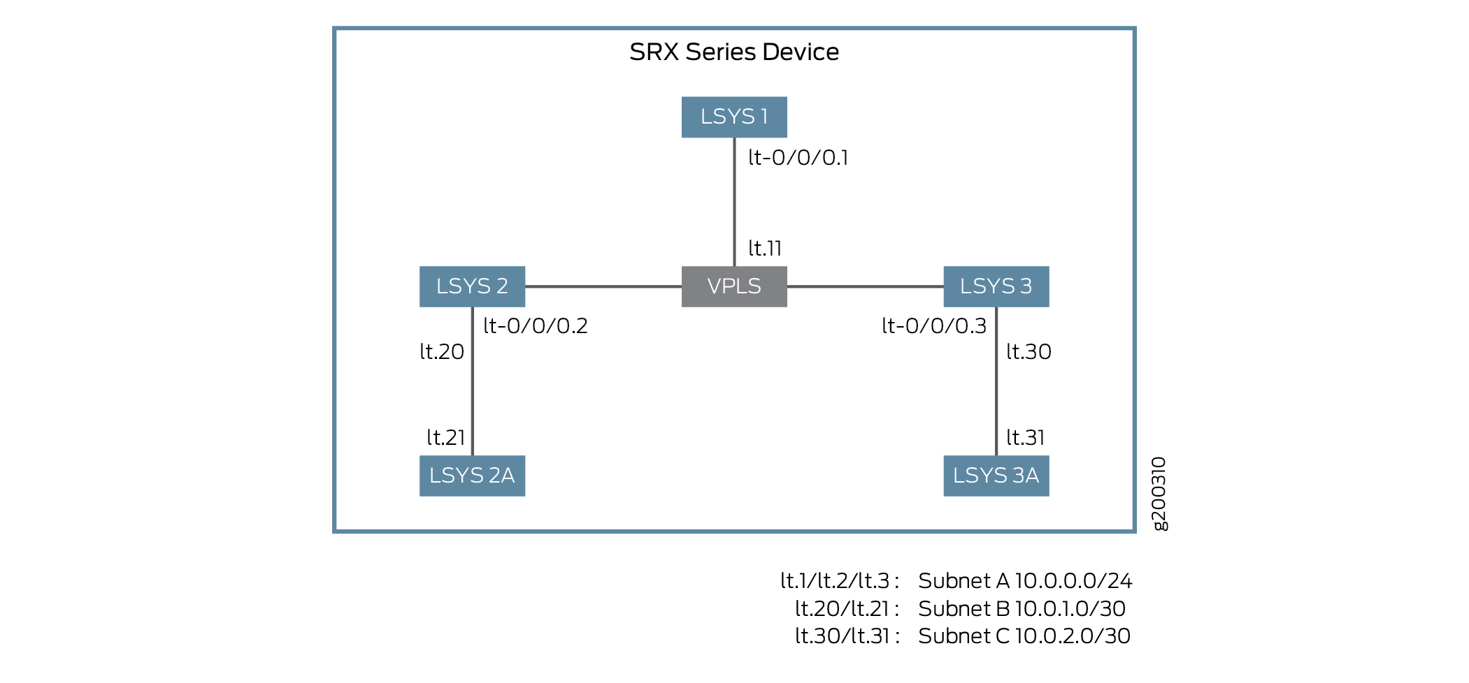
Table 1 describes the logical system interconnect configuration overview.
| Scenario | Encapsulation Type | Interfaces Configured | Key Configuration Details |
|---|---|---|---|
| Point-to-point interconnect logical systems | Ethernet | lt-0/0/0 and corresponding peer interfaces | Configure security zones, assign interfaces to logical systems, and apply a security profile |
| Point-to-point interconnect logical systems | Frame-relay | lt-0/0/0 and corresponding peer interfaces | Configure security zones, assign interfaces to logical systems, and apply a security profile |
| Interconnect logical systems with multiple VPLS switches | Ethernet-VPLS | lt-0/0/0 and corresponding peer interfaces | Assign security profiles and configure routing instances for VPLS switch-1 and switch-2 |
Configuration
To configure interfaces for the logical system, perform these tasks:
- Configure Logical Systems Interconnect with Logical Tunnel Interface point-to-point connection (Encapsulation Ethernet)
- Configure Logical Systems Interconnect with Logical Tunnel Interface point-to-point connection (Encapsulation Frame-Relay)
- Configure Logical Systems Interconnect with Multiple VPLS Switches
Configure Logical Systems Interconnect with Logical Tunnel Interface point-to-point connection (Encapsulation Ethernet)
CLI Quick Configuration
To quickly configure this example, copy the
following commands, paste them into a text file, remove any line breaks,
change any details necessary to match your network configuration,
copy and paste the commands into the CLI at the [edit] hierarchy
level, and then enter commit from configuration mode.
set system security-profile SP-user logical-system LSYS2
set logical-systems LSYS2 interfaces lt-0/0/0 unit 20 encapsulation ethernet
set logical-systems LSYS2 interfaces lt-0/0/0 unit 20 peer-unit 21
set logical-systems LSYS2 interfaces lt-0/0/0 unit 20 family inet address 192.255.2.1/30
set logical-systems LSYS2 security zones security-zone LT interfaces lt-0/0/0.20
set system security-profile SP-user logical-system LSYS2A
set logical-systems LSYS2A interfaces lt-0/0/0 unit 21 encapsulation ethernet
set logical-systems LSYS2A interfaces lt-0/0/0 unit 21 peer-unit 20
set logical-systems LSYS2A interfaces lt-0/0/0 unit 21 family inet address 192.255.2.2/30
set logical-systems LSYS2A security policies from-zone LT to-zone LT policy LT match source-address any
set logical-systems LSYS2A security policies from-zone LT to-zone LT policy LT match destination-address any
set logical-systems LSYS2A security policies from-zone LT to-zone LT policy LT match application any
set logical-systems LSYS2A security policies from-zone LT to-zone LT policy LT then permit
set logical-systems LSYS2A security policies default-policy permit-all
set logical-systems LSYS2A security zones security-zone LT host-inbound-traffic system-services all
set logical-systems LSYS2A security zones security-zone LT host-inbound-traffic protocols all
set logical-systems LSYS2A security zones security-zone LT interfaces lt-0/0/0.21
Step-by-Step Procedure
The following example requires you to navigate various levels in the configuration hierarchy. For instructions on how to do that, see Using the CLI Editor in Configuration Mode in the Junos OS CLI User Guide.
-
Define a security profile and assign to a logical system.
[edit]
user@host# set system security-profile SP-user logical-system LSYS2
-
Set the LT interface as encapsulation ethernet in the logical system.
[edit]
user@host# set logical-systems LSYS2 interfaces lt-0/0/0 unit 20 encapsulation ethernet
-
Configure a peer relationship for logical systems LSYS2.
[edit]
user@host# set logical-systems LSYS2 interfaces lt-0/0/0 unit 20 peer-unit 21
-
Specify the IP address for the LT interface.
[edit]
user@host# set logical-systems LSYS2 interfaces lt-0/0/0 unit 20 family inet address 192.255.2.1/30
-
Set the security zone for the LT interface.
[edit]
user@host# set logical-systems LSYS2 security zones security-zone LT interfaces lt-0/0/0.20
-
Define a security profile and assign to a logical system.
[edit]
user@host# set system security-profile SP-user logical-system LSYS2A
-
Set the LT interface as encapsulation ethernet in the logical system 2A.
[edit]
user@host# set logical-systems LSYS2A interfaces lt-0/0/0 unit 21 encapsulation ethernet
-
Configure a peer relationship for logical systems LSYS2A.
[edit]
user@host# set logical-systems LSYS2A interfaces lt-0/0/0 unit 21 peer-unit 20
-
Specify the IP address for the LT interface.
[edit]
user@host# set logical-systems LSYS2A interfaces lt-0/0/0 unit 21 family inet address 192.255.2.2/30
-
Configure a security policy that permits traffic from the LT zone to the LT policy LT zone.
[edit]
user@host# set logical-systems LSYS2A security policies from-zone LT to-zone LT policy LT match source-address any
user@host# set logical-systems LSYS2A security policies from-zone LT to-zone LT policy LT match destination-address any
user@host# set logical-systems LSYS2A security policies from-zone LT to-zone LT policy LT match application any
user@host# set logical-systems LSYS2A security policies from-zone LT to-zone LT policy LT then permit
-
Configure a security policy that permits traffic from default-policy.
[edit]
user@host# set logical-systems LSYS2A security policies default-policy permit-all
-
Configure security zones.
[edit]
user@host# set logical-systems LSYS2A security zones security-zone LT host-inbound-traffic system-services all
user@host# set logical-systems LSYS2A security zones security-zone LT host-inbound-traffic protocols all
user@host# set logical-systems LSYS2A security zones security-zone LT interfaces lt-0/0/0.21
Results
-
From configuration mode, confirm your configuration by entering the
show logical-systems LSYS2command. If the output does not display the intended configuration, repeat the configuration instructions in this example to correct it.[edit] user@host# show logical-systems LSYS2 interfaces { lt-0/0/0 { unit 20 { encapsulation ethernet; peer-unit 21; family inet { address 192.255.2.1/30; } } unit 22 { encapsulation ethernet; peer-unit 23; family inet { address 192.255.4.1/30; } } } } security { zones { security-zone LT { interfaces { lt-0/0/0.22; lt-0/0/0.20; } } } }
-
From configuration mode, confirm your configuration by entering the
show logical-systems LSYS2Acommand. If the output does not display the intended configuration, repeat the configuration instructions in this example to correct it.[edit] user@host# show logical-systems LSYS2A interfaces { lt-0/0/0 { unit 21 { encapsulation ethernet; peer-unit 20; family inet { address 192.255.2.2/30; } } } } security { policies { from-zone LT to-zone LT { policy LT { match { source-address any; destination-address any; application any; } then { permit; } } } default-policy { permit-all; } } zones { security-zone LT { host-inbound-traffic { system-services { all; } protocols { all; } } interfaces { lt-0/0/0.21; } } } }
If you are done configuring the device, enter commit from configuration mode.
Configure Logical Systems Interconnect with Logical Tunnel Interface point-to-point connection (Encapsulation Frame-Relay)
CLI Quick Configuration
To quickly configure this example, copy the
following commands, paste them into a text file, remove any line breaks,
change any details necessary to match your network configuration,
copy and paste the commands into the CLI at the [edit] hierarchy
level, and then enter commit from configuration mode.
set system security-profile SP-user logical-system LSYS3A
set logical-systems LSYS3 interfaces lt-0/0/0 unit 30 encapsulation frame-relay
set logical-systems LSYS3 interfaces lt-0/0/0 unit 30 dlci 16
set logical-systems LSYS3 interfaces lt-0/0/0 unit 30 peer-unit 31
set logical-systems LSYS3 interfaces lt-0/0/0 unit 30 family inet address 192.255.3.1/30
set logical-systems LSYS3 security zones security-zone LT interfaces lt-0/0/0.30
set logical-systems LSYS3A interfaces lt-0/0/0 unit 31 encapsulation frame-relay
set logical-systems LSYS3A interfaces lt-0/0/0 unit 31 dlci 16
set logical-systems LSYS3A interfaces lt-0/0/0 unit 31 peer-unit 30
set logical-systems LSYS3A interfaces lt-0/0/0 unit 31 family inet address 192.255.3.2/30
set logical-systems LSYS3A security policies from-zone LT to-zone LT policy LT match source-address any
set logical-systems LSYS3A security policies from-zone LT to-zone LT policy LT match destination-address any
set logical-systems LSYS3A security policies from-zone LT to-zone LT policy LT match application any
set logical-systems LSYS3A security policies from-zone LT to-zone LT policy LT then permit
set logical-systems LSYS3A security policies default-policy permit-all
set logical-systems LSYS3A security zones security-zone LT host-inbound-traffic system-services all
set logical-systems LSYS3A security zones security-zone LT host-inbound-traffic protocols all
set logical-systems LSYS3A security zones security-zone LT interfaces lt-0/0/0.31
Step-by-Step Procedure
The following example requires you to navigate various levels in the configuration hierarchy. For instructions on how to do that, see Using the CLI Editor in Configuration Mode.
-
Define a security profile and assign to a logical system.
[edit]
user@host# set system security-profile SP-user logical-system LSYS3A
-
Set the LT interface as encapsulation frame-relay in the logical system.
[edit]
user@host# set logical-systems LSYS3 interfaces lt-0/0/0 unit 30 encapsulation frame-relay
-
Configure the logical tunnel interface by including the dlci.
[edit]
user@host# set logical-systems LSYS3 interfaces lt-0/0/0 unit 30 dlci 16
-
Configure a peer unit relationship between LT interfaces, thus creating a point-to-point connection.
[edit]
user@host# set logical-systems LSYS3 interfaces lt-0/0/0 unit 30 peer-unit 31
-
Specify the IP address for the LT interface.
[edit]
user@host# set logical-systems LSYS3 interfaces lt-0/0/0 unit 30 family inet address 192.255.3.1/30
-
Set the security zone for the LT interface.
[edit]
user@host# set logical-systems LSYS3 security zones security-zone LT interfaces lt-0/0/0.30
-
Set the LT interface as encapsulation frame-relay in the logical system.
[edit]
user@host# set logical-systems LSYS3A interfaces lt-0/0/0 unit 31 encapsulation frame-relay
-
Configure the logical tunnel interface by including the dlci.
[edit]
user@host# set logical-systems LSYS3A interfaces lt-0/0/0 unit 31 dlci 16
-
Configure a peer unit relationship between LT interfaces, thus creating a point-to-point connection.
[edit]
user@host# set logical-systems LSYS3A interfaces lt-0/0/0 unit 31 peer-unit 30
-
Specify the IP address for the LT interface.
[edit]
user@host# set logical-systems LSYS3A interfaces lt-0/0/0 unit 31 family inet address 192.255.3.2/30
-
Configure a security policy that permits traffic from the LT zone to the LT policy LT zone.
[edit]
user@host# set logical-systems LSYS3A security policies from-zone LT to-zone LT policy LT match source-address any
user@host# set logical-systems LSYS3A security policies from-zone LT to-zone LT policy LT match destination-address any
user@host# set logical-systems LSYS3A security policies from-zone LT to-zone LT policy LT match application any
user@host# set logical-systems LSYS3A security policies from-zone LT to-zone LT policy LT then permit
-
Configure a security policy that permits traffic from default-policy.
[edit]
user@host# set logical-systems LSYS3A security policies default-policy permit-all
-
Configure security zones.
[edit]
user@host# set logical-systems LSYS3A security zones security-zone LT host-inbound-traffic system-services all
user@host# set logical-systems LSYS3A security zones security-zone LT host-inbound-traffic protocols all
user@host# set logical-systems LSYS3A security zones security-zone LT interfaces lt-0/0/0.31
Results
-
From configuration mode, confirm your configuration by entering the
show logical-systems LSYS3commands. If the output does not display the intended configuration, repeat the configuration instructions in this example to correct it.[edit] user@host# show logical-systems LSYS3 interfaces { lt-0/0/0 { unit 30 { encapsulation frame-relay; dlci 16; peer-unit 31; family inet { address 192.255.3.1/30; } } } } security { zones { security-zone LT { interfaces { lt-0/0/0.30; } } } }
-
From configuration mode, confirm your configuration by entering the
show logical-systems LSYS3Acommands. If the output does not display the intended configuration, repeat the configuration instructions in this example to correct it.[edit] user@host# show logical-systems LSYS3A
    interfaces {
        lt-0/0/0 {
            unit 31 {
                encapsulation frame-relay;
                dlci 16;
                peer-unit 30;
                family inet {
                    address 192.255.3.2/30;
                }
            }
        }
    }
    security {
        policies {
            from-zone LT to-zone LT {
                policy LT {
                    match {
                        source-address any;
                        destination-address any;
                        application any;
                    }
                    then {
                        permit;
                    }
                }
            }
            default-policy {
                permit-all;
            }
        }
        zones {
            security-zone LT {
                host-inbound-traffic {
                    system-services {
                        all;
                    }
                    protocols {
                        all;
                    }
                }
                interfaces {
                    lt-0/0/0.31;
                }
            }
        }
    }
If you are done configuring the device, enter commit from configuration mode.
Configure Logical Systems Interconnect with Multiple VPLS Switches
CLI Quick Configuration
To quickly configure this example, copy the
following commands, paste them into a text file, remove any line breaks,
change any details necessary to match your network configuration,
copy and paste the commands into the CLI at the [edit] hierarchy
level, and then enter commit from configuration mode.
set interfaces lt-0/0/0 unit 11 encapsulation ethernet-vpls
set interfaces lt-0/0/0 unit 11 peer-unit 1
set interfaces lt-0/0/0 unit 12 encapsulation ethernet-vpls
set interfaces lt-0/0/0 unit 12 peer-unit 2
set interfaces lt-0/0/0 unit 13 encapsulation ethernet-vpls
set interfaces lt-0/0/0 unit 13 peer-unit 3
set interfaces lt-0/0/0 unit 23 encapsulation ethernet-vpls
set interfaces lt-0/0/0 unit 23 peer-unit 22
set interfaces lt-0/0/0 unit 25 encapsulation ethernet-vpls
set interfaces lt-0/0/0 unit 25 peer-unit 24
set routing-instances vpls-switch-1 instance-type vpls
set routing-instances vpls-switch-1 interface lt-0/0/0.11
set routing-instances vpls-switch-1 interface lt-0/0/0.12
set routing-instances vpls-switch-1 interface lt-0/0/0.13
set routing-instances vpls-switch-2 instance-type vpls
set routing-instances vpls-switch-2 interface lt-0/0/0.23
set routing-instances vpls-switch-2 interface lt-0/0/0.25
set logical-systems LSYS1 interfaces lt-0/0/0 unit 1 encapsulation ethernet
set logical-systems LSYS1 interfaces lt-0/0/0 unit 1 peer-unit 11
set logical-systems LSYS1 interfaces lt-0/0/0 unit 1 family inet address 192.255.0.1/24
set logical-systems LSYS2 interfaces lt-0/0/0 unit 2 encapsulation ethernet
set logical-systems LSYS2 interfaces lt-0/0/0 unit 2 peer-unit 12
set logical-systems LSYS2 interfaces lt-0/0/0 unit 2 family inet address 192.255.0.2/24
set logical-systems LSYS2 interfaces lt-0/0/0 unit 22 encapsulation ethernet
set logical-systems LSYS2 interfaces lt-0/0/0 unit 22 peer-unit 23
set logical-systems LSYS2 interfaces lt-0/0/0 unit 22 family inet address 192.255.4.1/30
set logical-systems LSYS3 interfaces lt-0/0/0 unit 3 encapsulation ethernet
set logical-systems LSYS3 interfaces lt-0/0/0 unit 3 peer-unit 13
set logical-systems LSYS3 interfaces lt-0/0/0 unit 3 family inet address 192.255.0.3/24
set logical-systems LSYS2B interfaces lt-0/0/0 unit 24 encapsulation ethernet
set logical-systems LSYS2B interfaces lt-0/0/0 unit 24 peer-unit 25
set logical-systems LSYS2B interfaces lt-0/0/0 unit 24 family inet address 192.255.4.2/30
set system security-profile SP-user policy maximum 100
set system security-profile SP-user policy reserved 50
set system security-profile SP-user zone maximum 60
set system security-profile SP-user zone reserved 10
set system security-profile SP-user flow-session maximum 100
set system security-profile SP-user flow-session reserved 50
set system security-profile SP-user logical-system LSYS1
set system security-profile SP-user logical-system LSYS2
set system security-profile SP-user logical-system LSYS3
set system security-profile SP-user logical-system LSYS2B
Step-by-Step Procedure
The following example requires you to navigate various levels in the configuration hierarchy. For instructions on how to do that, see Using the CLI Editor in Configuration Mode.
-
Configure the lt-0/0/0 interfaces.
[edit]
user@host# set interfaces lt-0/0/0 unit 11 encapsulation ethernet-vpls
user@host# set interfaces lt-0/0/0 unit 11 peer-unit 1
user@host# set interfaces lt-0/0/0 unit 12 encapsulation ethernet-vpls
user@host# set interfaces lt-0/0/0 unit 12 peer-unit 2
user@host# set interfaces lt-0/0/0 unit 13 encapsulation ethernet-vpls
user@host# set interfaces lt-0/0/0 unit 13 peer-unit 3
user@host# set interfaces lt-0/0/0 unit 23 encapsulation ethernet-vpls
user@host# set interfaces lt-0/0/0 unit 23 peer-unit 22
user@host# set interfaces lt-0/0/0 unit 25 encapsulation ethernet-vpls
user@host# set interfaces lt-0/0/0 unit 25 peer-unit 24
-
Configure the routing instance for the VPLS switches and add interfaces to it.
[edit]
user@host# set routing-instances vpls-switch-1 instance-type vpls
user@host# set routing-instances vpls-switch-1 interface lt-0/0/0.11
user@host# set routing-instances vpls-switch-1 interface lt-0/0/0.12
user@host# set routing-instances vpls-switch-1 interface lt-0/0/0.13
user@host# set routing-instances vpls-switch-2 instance-type vpls
user@host# set routing-instances vpls-switch-2 interface lt-0/0/0.23
user@host# set routing-instances vpls-switch-2 interface lt-0/0/0.25
-
Configure LSYS1 with lt-0/0/0.1 interface and peer lt-0/0/0.11.
[edit]
user@host# set logical-systems LSYS1 interfaces lt-0/0/0 unit 1 encapsulation ethernet
user@host# set logical-systems LSYS1 interfaces lt-0/0/0 unit 1 peer-unit 11
user@host# set logical-systems LSYS1 interfaces lt-0/0/0 unit 1 family inet address 192.255.0.1/24
-
Configure LSYS2 with lt-0/0/0.2 interface and peer lt-0/0/0.12.
[edit]
user@host# set logical-systems LSYS2 interfaces lt-0/0/0 unit 2 encapsulation ethernet
user@host# set logical-systems LSYS2 interfaces lt-0/0/0 unit 2 peer-unit 12
user@host# set logical-systems LSYS2 interfaces lt-0/0/0 unit 2 family inet address 192.255.0.2/24
user@host# set logical-systems LSYS2 interfaces lt-0/0/0 unit 22 encapsulation ethernet
user@host# set logical-systems LSYS2 interfaces lt-0/0/0 unit 22 peer-unit 23
user@host# set logical-systems LSYS2 interfaces lt-0/0/0 unit 22 family inet address 192.255.4.1/30
-
Configure LSYS3 with lt-0/0/0.3 interface and peer lt-0/0/0.13
[edit]
user@host# set logical-systems LSYS3 interfaces lt-0/0/0 unit 3 encapsulation ethernet
user@host# set logical-systems LSYS3 interfaces lt-0/0/0 unit 3 peer-unit 13
user@host# set logical-systems LSYS3 interfaces lt-0/0/0 unit 3 family inet address 192.255.0.3/24
-
Configure LSYS2B with lt-0/0/0 interface and peer-unit 24.
[edit]
user@host# set logical-systems LSYS2B interfaces lt-0/0/0 unit 24 encapsulation ethernet
user@host# set logical-systems LSYS2B interfaces lt-0/0/0 unit 24 peer-unit 25
user@host# set logical-systems LSYS2B interfaces lt-0/0/0 unit 24 family inet address 192.255.4.2/30
-
Assign security-profile for logical-systems.
[edit]
user@host# set system security-profile SP-user policy maximum 100
user@host# set system security-profile SP-user policy reserved 50
user@host# set system security-profile SP-user zone maximum 60
user@host# set system security-profile SP-user zone reserved 10
user@host# set system security-profile SP-user flow-session maximum 100
user@host#set system security-profile SP-user flow-session reserved 50
user@host# set system security-profile SP-user logical-system LSYS1
user@host# set system security-profile SP-user logical-system LSYS2
user@host# set system security-profile SP-user logical-system LSYS3
user@host# set system security-profile SP-user logical-system LSYS2B
Results
-
From configuration mode, confirm your configuration by entering the
show interfaces lt-0/0/0, command. If the output does not display the intended configuration, repeat the configuration instructions in this example to correct it[edit] user@host# show interfaces lt-0/0/0 unit 11 { encapsulation ethernet-vpls; peer-unit 1; } unit 12 { encapsulation ethernet-vpls; peer-unit 2; } unit 13 { encapsulation ethernet-vpls; peer-unit 3; } unit 23 { encapsulation ethernet-vpls; peer-unit 22; } unit 25 { encapsulation ethernet-vpls; peer-unit 24; } -
From configuration mode, confirm your configuration by entering the
show routing-instances, command. If the output does not display the intended configuration, repeat the configuration instructions in this example to correct it.[edit] user@host# show routing-instances vpls-switch-1 { instance-type vpls; interface lt-0/0/0.11; interface lt-0/0/0.12; interface lt-0/0/0.13; } vpls-switch-2 { instance-type vpls; interface lt-0/0/0.23; interface lt-0/0/0.25; } -
From configuration mode, confirm your configuration by entering the
show logical-systems LSYS1, command. If the output does not display the intended configuration, repeat the configuration instructions in this example to correct it.[edit] user@host# show logical-systems LSYS1 interfaces { lt-0/0/0 { unit 1 { encapsulation ethernet; peer-unit 11; family inet { address 192.255.0.1/24; } } } } -
From configuration mode, confirm your configuration by entering the
show logical-systems LSYS2, command. If the output does not display the intended configuration, repeat the configuration instructions in this example to correct it.[edit] user@host# show logical-systems LSYS2 interfaces { lt-0/0/0 { unit 2 { encapsulation ethernet; peer-unit 12; family inet { address 192.255.0.2/24; } } unit 22 { encapsulation ethernet; peer-unit 23; family inet { address 192.255.4.1/30; } } } } -
From configuration mode, confirm your configuration by entering the
show logical-systems LSYS3, command. If the output does not display the intended configuration, repeat the configuration instructions in this example to correct it.[edit] user@host# show logical-systems LSYS3 interfaces { lt-0/0/0 { unit 3 { encapsulation ethernet; peer-unit 13; family inet { address 192.255.0.3/24; } } } } -
From configuration mode, confirm your configuration by entering the
show logical-systems LSYS2B, command. If the output does not display the intended configuration, repeat the configuration instructions in this example to correct it.[edit] user@host# show logical-systems LSYS2B interfaces { lt-0/0/0 { unit 24 { encapsulation ethernet; peer-unit 25; family inet { address 192.255.4.2/30; } } } } -
From configuration mode, confirm your configuration by entering the
show system security-profile, command. If the output does not display the intended configuration, repeat the configuration instructions in this example to correct it.[edit] user@host# show system security-profile SP-user { policy { maximum 100; reserved 50; } zone { maximum 60; reserved 10; } flow-session { maximum 100; reserved 50; } logical-system [ LSYS1 LSYS2 LSYS3 LSYS2B ]; }
If you are done configuring the device, enter commit from configuration mode.
Verification
To confirm that the configuration is working properly, perform these tasks:
- Verify the Security-Profile for all Logical-systems
- Verify the LT Interfaces for all Logical systems
Verify the Security-Profile for all Logical-systems
Purpose
Verify security profile for each logical systems.
Action
From operational mode, enter the show system security-profile
security-log-stream-number logical-system all command.
user@host> show system security-profile security-log-stream-number logical-system all
logical system name   security profile name       usage    reserved   maximum
root-logical-system   Default-Profile                 2           0          2000
LSYS1                 SP-user                         1          10          60
LSYS2                 SP-user                         1          10          60
LSYS2B                SP-user                         1          10          60
LSYS3                 SP-user                         1          10          60
Meaning
The output provides the usage and reserved values for the logical systems when security-log-stream is configured.
Verify the LT Interfaces for all Logical systems
Purpose
Verify interfaces for logical systems.
Action
From operational mode, enter the show interfaces
lt-0/0/0 terse command.
user@host> show interfaces lt-0/0/0 terse
Interface               Admin Link Proto    Local                 Remote
lt-0/0/0                up    up
lt-0/0/0.1              up    up   inet     192.255.0.1/24
lt-0/0/0.2              up    up   inet     192.255.0.2/24
lt-0/0/0.3              up    up   inet     192.255.0.3/24
lt-0/0/0.11             up    up   vpls
lt-0/0/0.12             up    up   vpls
lt-0/0/0.13             up    up   vpls
lt-0/0/0.22             up    up   inet     192.255.4.1/30
lt-0/0/0.23             up    up   vpls
lt-0/0/0.24             up    up   inet     192.255.4.2/30
lt-0/0/0.25             up    up   vpls
lt-0/0/0.32767          up    up
Meaning
The output provides the status of LT interfaces. All the LT interfaces are up.