VPNs in Logical Systems
A VPN is an encrypted connection over the Internet from a device to a network. The encrypted connection helps ensure that sensitive data is safely transmitted. VPN prevents unauthorized access eavesdropping on the traffic, and allows the user to conduct work remotely. For more information, see the following topics:
Understanding Route-Based VPN Tunnels in Logical Systems
A VPN connection can secure traffic that passes between a logical system and a remote site across a WAN. With route-based VPNs, you configure one or more security policies in a logical system to regulate the traffic flowing through a single IP Security (IPsec) tunnel. For each IPsec tunnel, there is one set of IKE and IPsec security associations (SAs) that must be configured at the root level by the primary administrator.
The external interface configured under the gateway configuration can only be a part of the root logical system.
Only route-based VPNs are supported in logical systems. Policy-based VPNs are not supported.
In addition to configuring IKE and IPsec SAs for each VPN, the primary administrator must also assign a secure tunnel (st0) interface to a user logical system. An st0 interface can only be assigned to a single user logical system. However, multiple user logical systems can each be assigned their own st0 interface.
The st0 unit 0 interface should not be assigned to a logical system, as an SA cannot be set up for this interface.
The user logical system administrator can configure the IP address and other attributes of the st0 interface assigned to the user logical system. The user logical system administrator cannot delete an st0 interface assigned to their user logical system.
For route-based VPNs, a security policy refers to a destination address and not a specific VPN tunnel. For cleartext traffic in a user logical system to be sent to the VPN tunnel for encapsulation, the user logical system administrator must make the following configurations:
Security policy that permits traffic to a specified destination.
Static route to the destination with the st0 interface as the next hop.
When Junos OS looks up routes in the user logical system to find the interface to use to send traffic to the destination address, it finds a static route through the st0 interface. Traffic is routed to the VPN tunnel as long as the security policy action is permit.
Traffic selectors are not supported in logical systems.
The primary logical system and a user logical system can share a route-based VPN tunnel. An st0 interface assigned to a user logical system can also be used by the primary logical system. For the primary logical system, the primary administrator configures a security policy that permits traffic to the remote destination and a static route to the remote destination with the st0 interface as the next hop.
VPN monitoring is configured by the primary administrator in the primary logical system. For the VPN monitor source interface, the primary administrator must specify the st0 interface; a physical interface for a user logical system cannot be specified.
See Also
Example: Configuring IKE and IPsec SAs for a VPN Tunnel (Primary Administrators Only)
The primary administrator is responsible for assigning an st0 interface to a user logical system and configuring IKE and IPsec SAs at the root level for each VPN tunnel. This example shows how to assign an st0 interface to a user logical system and configure IKE and IPsec SA parameters.
Requirements
Before you begin:
-
Log in to the primary logical system as the primary administrator. See “Understanding the Primary Logical Systems and the Primary Administrator Role.
Overview
In this example you configure a VPN tunnel for the ls-product-design user logical system. This example configures the VPN tunnel parameters described in Table 1.
|
Feature |
Name |
Configuration Parameters |
|---|---|---|
|
Tunnel interface |
st0 unit 1 |
Assigned to ls-product-design logical system |
|
IKE proposal |
ike-phase1-proposal |
|
|
IKE policy |
|
|
|
IKE gateway |
ike-gw |
|
|
IPsec proposal |
ipsec-phase2-proposal |
|
|
IPsec policy |
vpn-policy1 |
|
|
VPN |
ike-vpn |
|
|
VPN monitoring |
For ike-vpn VPN:
|
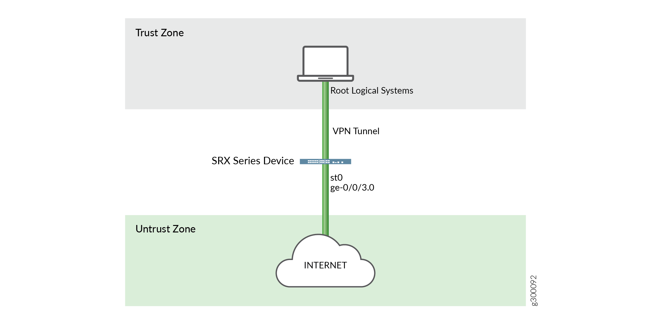
Topology
Figure 1 shows the topology for logical systems VPN tunnel.
Configuration
Procedure
CLI Quick Configuration
To quickly configure this example, copy the
following commands, paste them into a text file, remove any line breaks,
change any details necessary to match your network configuration,
copy and paste the commands into the CLI at the [edit] hierarchy
level, and then enter commit from configuration mode.
set logical-systems ls-product-design interfaces st0 unit 1
set security ike proposal ike-phase1-proposal authentication-method pre-shared-keys
set security ike proposal ike-phase1-proposal dh-group group2
set security ike proposal ike-phase1-proposal authentication-algorithm sha1
set security ike proposal ike-phase1-proposal encryption-algorithm aes-128-cbc
set security ike policy ike-phase1-policy mode main
set security ike policy ike-phase1-policy proposals ike-phase1-proposal
set security ike policy ike-phase1-policy pre-shared-key ascii-text "$ABC123"
set security ike gateway ike-gw ike-policy ike-phase1-policy
set security ike gateway ike-gw address 2.2.2.2
set security ike gateway ike-gw external-interface ge-0/0/3.0
set security ipsec proposal ipsec-phase2-proposal protocol esp
set security ipsec proposal ipsec-phase2-proposal authentication-algorithm hmac-sha1-96
set security ipsec proposal ipsec-phase2-proposal encryption-algorithm aes-128-cbc
set security ipsec policy vpn-policy1 perfect-forward-secrecy keys group2
set security ipsec policy vpn-policy1 proposals ipsec-phase2-proposal
set security ipsec vpn ike-vpn bind-interface st0.1
set security ipsec vpn ike-vpn vpn-monitor source-interface st0.1
set security ipsec vpn ike-vpn vpn-monitor destination-ip 4.0.0.1
set security ipsec vpn ike-vpn ike gateway ike-gw
set security ipsec vpn ike-vpn ike ipsec-policy vpn-policy1
Step-by-Step Procedure
The following example requires you to navigate various levels in the configuration hierarchy. For instructions on how to do that, see Using the CLI Editor in Configuration Mode in the Junos OS CLI User Guide.
To assign a VPN tunnel interface to a user logical system and configure IKE and IPsec SAs:
-
Log in to the primary logical system as the primary administrator and enter configuration mode.
[edit]
admin@host> configure
admin@host#
-
Assign a VPN tunnel interface.
[edit logical-systems ls-product-design]
admin@host# set interfaces st0 unit 1
-
Configure an IKE proposal.
[edit security ike]
admin@host# set proposal ike-phase1-proposal authentication-method pre-shared-keys
admin@host# set proposal ike-phase1-proposal dh-group group2
admin@host# set proposal ike-phase1-proposal authentication-algorithm sha1
admin@host# set proposal ike-phase1-proposal encryption-algorithm aes-128-cbc
-
Configure an IKE policy.
[edit security ike]
admin@host# set policy ike-phase1-policy mode main
admin@host# set policy ike-phase1-policy proposals ike-phase1-proposal
admin@host# set policy ike-phase1-policy pre-shared-key ascii-text 395psksecr3t
-
Configure an IKE gateway.
[edit security ike]
admin@host# set gateway ike-gw external-interface ge-0/0/3.0
admin@host# set gateway ike-gw ike-policy ike-phase1-policy
admin@host# set gateway ike-gw address 2.2.2.2
-
Configure an IPsec proposal.
[edit security ipsec]
admin@host# set proposal ipsec-phase2-proposal protocol esp
admin@host# set proposal ipsec-phase2-proposal authentication-algorithm hmac-sha1-96
admin@host# set proposal ipsec-phase2-proposal encryption-algorithm aes-128-cbc
-
Configure an IPsec policy.
[edit security ipsec]
admin@host# set policy vpn-policy1 proposals ipsec-phase2-proposal
admin@host# set policy vpn-policy1 perfect-forward-secrecy keys group2
-
Configure the VPN.
[edit security ipsec]
admin@host# set vpn ike-vpn bind-interface st0.1
admin@host# set vpn ike-vpn ike gateway ike-gw
admin@host# set vpn ike-vpn ike ipsec-policy vpn-policy1
-
Configure VPN monitoring.
[edit security ipsec]
admin@host# set vpn ike-vpn vpn-monitor source-interface st0.1
admin@host# set vpn ike-vpn vpn-monitor destination-ip 4.0.0.1
Results
From configuration mode, confirm your configuration
by entering the show interfaces, show security ike, and show security ipsec commands. If the output does
not display the intended configuration, repeat the instructions in
this example to correct the configuration.
[edit]
admin@host# show interfaces
    st0 {
        unit 1;
    }
[edit]
admin@host# show security ike
    proposal ike-phase1-proposal {
        authentication-method pre-shared-keys;
        dh-group group2;
        authentication-algorithm sha1;
        encryption-algorithm aes-128-cbc;
    }
        policy ike-phase1-policy {
            mode main;
            proposals ike-phase1-proposal;
            pre-shared-key ascii-text "$ABC123"; ## SECRET-DATA
        }
        gateway ike-gw {
            ike-policy ike-phase1-policy;
            address 2.2.2.2;
            external-interface ge-0/0/3.0;
        }
[edit]
admin@host# show security ipsec
    proposal ipsec-phase2-proposal {
        protocol esp;
        authentication-algorithm hmac-sha1-96;
        encryption-algorithm aes-128-cbc;
    }
        policy vpn-policy1 {
            perfect-forward-secrecy {
                keys group2;
            }
            proposals ipsec-phase2-proposal;
        }
        vpn ike-vpn {
            bind-interface st0.1;
            vpn-monitor {
                source-interface st0.1;
                destination-ip 4.0.0.1;
            }
            ike {
                gateway ike-gw;
                ipsec-policy vpn-policy1;
            }
        }
If you are done configuring the device, enter commit from configuration mode.
Verification
To confirm that the configuration is working properly, perform these tasks:
Verifying the IKE on Logical System
Purpose
Verify that the IKE support on Logical Systems.
Action
From operational mode, enter the show security
ike sa detail command.
user@host> show security ike sa detail
IKE peer 2.2.2.2, Index 7796166, Gateway Name: GW1
  Role: Initiator, State: UP
  Initiator cookie: a1a6b1516bc43d54, Responder cookie: f0846e4239c817f8
  Exchange type: Aggressive, Authentication method: Pre-shared-keys
  Local: 3.3.3.2:500, Remote: 2.2.2.2:500
  Lifetime: Expires in 3585 seconds
  Reauth Lifetime: Disabled
  IKE Fragmentation: Disabled, Size: 0
  Remote Access Client Info: Unknown Client
  Peer ike-id: 2.2.2.2
  AAA assigned IP: 0.0.0.0
  Algorithms:
   Authentication        : hmac-sha256-128
   Encryption            : aes256-cbc
   Pseudo random function: hmac-sha256
   Diffie-Hellman group  : DH-group-14
  Traffic statistics:
   Input  bytes  :                 1056
   Output bytes  :                 1311
   Input  packets:                    2
   Output packets:                    4
   Input  fragmentated packets:       0
   Output fragmentated packets:       0
  IPSec security associations: 1 created, 0 deleted
  Phase 2 negotiations in progress: 1

    Negotiation type: Quick mode, Role: Initiator, Message ID: 0
    Local: 3.3.3.2:500, Remote: 2.2.2.2:500
    Local identity: r0r2_store1@juniper.net
    Remote identity: 2.2.2.2
    Flags: IKE SA is created
Meaning
The output displays summary information about ike details.
Verifying the IPsec on Logical System
Purpose
Verify that the IPsec SA support on Logical Systems.
Action
From operational mode, enter the show security ipsec sa detail command.
user@host> show security ipsec sa detail
ID: 67109793 Virtual-system: root, VPN Name: VPN1
  Local Gateway: 3.3.3.2, Remote Gateway: 2.2.2.2
  Traffic Selector Name: VPN1_TS1
  Local Identity: ipv4(51.0.1.0-51.0.1.255)
  Remote Identity: ipv4(41.0.1.0-41.0.1.255)
  Version: IKEv1
  DF-bit: clear, Copy-Outer-DSCP Disabled, Bind-interface: st0.1
  Port: 500, Nego#: 0, Fail#: 0, Def-Del#: 0 Flag: 0x2c608b29
  Tunnel events:
    Wed Aug 16 2017 23:50:07 -0700: IPSec SA negotiation successfully completed (1 times)
    Wed Aug 16 2017 23:50:07 -0700: IKE SA negotiation successfully completed (1 times)
    Wed Aug 16 2017 23:49:46 -0700: Negotiation failed with error code AUTHENTICATION_FAILED received from peer (2 times)
    Wed Aug 16 2017 23:49:30 -0700: Tunnel is ready. Waiting for trigger event or peer to trigger negotiation (1 times)
  Direction: inbound, SPI: e651d79e, AUX-SPI: 0, VPN Monitoring: -
    Hard lifetime: Expires in 2552 seconds
    Lifesize Remaining:  Unlimited
    Soft lifetime: Expires in 1988 seconds
    Mode: Tunnel(0 0), Type: dynamic, State: installed
    Protocol: ESP, Authentication: hmac-sha256-128, Encryption: aes-cbc (256 bits)
    Anti-replay service: counter-based enabled, Replay window size: 64
  Direction: outbound, SPI: 8ac9ce8, AUX-SPI: 0, VPN Monitoring: -
    Hard lifetime: Expires in 2552 seconds
    Lifesize Remaining:  Unlimited
    Soft lifetime: Expires in 1988 seconds
    Mode: Tunnel(0 0), Type: dynamic, State: installed
    Protocol: ESP, Authentication: hmac-sha256-128, Encryption: aes-cbc (256 bits)
    Anti-replay service: counter-based enabled, Replay window size: 64
Meaning
The output displays summary information about ipsec details.
Example: Configuring a Route-Based VPN Tunnel in a User Logical Systems
This example shows how to configure a route-based VPN tunnel in a user logical system.
Requirements
Before you begin:
Log in to the user logical system as the logical system administrator. See User Logical Systems Configuration Overview.
Ensure that an st0 interface is assigned to the user logical system and IKE and IPsec SAs are configured at the root level by the primary administrator. See Example: Configuring IKE and IPsec SAs for a VPN Tunnel (Primary Administrators Only).
Overview
In this example, you configure the ls-product-design user logical system as shown in Example: Creating User Logical Systems, Their Administrators, Their Users, and an Interconnect Logical System.
You configure the route-based VPN parameters described in Table 2.
Feature |
Name |
Configuration Parameters |
|---|---|---|
Tunnel interface |
st0 unit 1 |
|
Static route |
|
|
Security policy |
through-vpn |
Permit the following traffic:
|
Configuration
Procedure
CLI Quick Configuration
To quickly configure this example, copy the
following commands, paste them into a text file, remove any line breaks,
change any details necessary to match your network configuration,
copy and paste the commands into the CLI at the [edit] hierarchy
level, and then enter commit from configuration mode.
set interfaces st0 unit 1 family inet address 10.11.11.150/24
set routing-options static route 192.168.168.0/24 next-hop st0.1
set security policies from-zone ls-product-design-trust to-zone ls-product-design-untrust policy through-vpn match source-address any
set security policies from-zone ls-product-design-trust to-zone ls-product-design-untrust policy through-vpn match destination-address 192.168.168.0/24
set security policies from-zone ls-product-design-trust to-zone ls-product-design-untrust policy through-vpn match application any
set security policies from-zone ls-product-design-trust to-zone ls-product-design-untrust policy through-vpn then permit
Step-by-Step Procedure
The following example requires you to navigate various levels in the configuration hierarchy. For instructions on how to do that, see Using the CLI Editor in Configuration Mode in the Junos OS CLI User Guide.
To configure a route-based VPN tunnel in a user logical system:
Log in to the user logical system as the logical system administrator and enter configuration mode.
[edit]
lsdesignadmin1@host:ls-product-design>configure
lsdesignadmin1@host:ls-product-design#
Configure the VPN tunnel interface.
[edit interfaces]
lsdesignadmin1@host:ls-product-design# set st0 unit 1 family inet address 10.11.11.150/24
Create a static route to the remote destination.
[edit routing-options]
lsdesignadmin1@host:ls-product-design# set static route 192.168.168.0/24 next-hop st0.1
Configure a security policy to permit traffic to the remote destination.
[edit security policies from-zone ls-product-design-trust to-zone ls-product-design-untrust]
lsdesignadmin1@host:ls-product-design# set policy through-vpn match source-address any
lsdesignadmin1@host:ls-product-design# set policy through-vpn match destination-address 192.168.168.0/24
lsdesignadmin1@host:ls-product-design# set policy through-vpn match application any
lsdesignadmin1@host:ls-product-design# set policy through-vpn then permit
Results
From configuration mode, confirm your configuration
by entering the show interfaces st0, show routing-options, and show security policies commands. If the output does
not display the intended configuration, repeat the instructions in
this example to correct the configuration.
[edit]
lsdesignadmin1@host:ls-product-design# show interfaces st0
    unit 1 {
        family inet {
            address 10.11.11.150/24;
        }
    }
    lsdesignadmin1@host:ls-product-design# show routing-options
        static {
            route 192.168.168.0/24 next-hop st0.1;
        }
    [edit]
    lsdesignadmin1@host:ls-product-design# show security policies
        from-zone ls-product-design-trust to-zone ls-product-design-untrust {
            policy through-vpn {
                match {
                    source-address any;
                    destination-address 192.168.168.0/24;
                    application any;
                }
                then {
                    permit;
                }
            }
            ...
        }
If you are done configuring the device, enter commit from configuration mode.
Verification
Confirm that the configuration is working properly.
Before starting the verification process, you need to send traffic from a host in the user logical system to a host in the 192.168.168.0/24 network. For example, initiate a ping from a host in the 12.1.1.0/24 subnet in the ls-product-design user logical system to the host 192.168.168.10.
Verifying the IKE Phase 1 Status
Purpose
Verify the IKE Phase 1 status.
Action
From operational mode, enter the show security
ike security-associations command. After obtaining an index
number from the command, use the show security ike security-associations
index index_number detail command.
For sample outputs and meanings, see the “Verification” section of Example: Configuring a Route-Based VPN.
Verifying the IPsec Phase 2 Status
Purpose
Verify the IPsec Phase 2 status.
Action
From operational mode, enter the show security
ipsec security-associations command. After obtaining an index
number from the command, use the show security ipsec security-associations
index index_number detail command.
For sample outputs and meanings, see the “Verification” section of Example: Configuring a Route-Based VPN.