IPv6 for Logical Systems
IPv6 builds upon the functionality of IPv4, providing improvements to IP addressing, configuration and maintenance, and security. IPv6 supports extensions for authentication and data integrity, which enhance privacy and security. IPv6 uses 128-bit addresses and supports a virtually unlimited number of devices—2 to the 128th power. For more information, see the following topics:
IPv6 Addresses in Logical Systems Overview
IP version 6 (IPv6) increases the size of an IP address from the 32 bits that compose an IPv4 address to 128 bits. Each extra bit given to an address doubles the size of its address space. IPv6 has a much larger address space than the soon-to-be exhausted IPv4 address space.
IPv6 addresses can be configured in logical systems for the following features:
Interfaces
Firewall authentication
Flows
Routing (BGP only)
Zones and security policies
Screen options
Network Address Translation (except for interface NAT)
Administrative operations such as SSH, HTTPS, and other utilities
Chassis clusters
An IPv6 session consumes twice the memory of an IPv4 session. Therefore the number of sessions available for IPv6 is half the reserved and maximum quotas configured for the flow session resource in a security profile. Use the vty command show usp flow resource usage cp-session to check flow session usage.
See Also
Understanding IPv6 Dual-Stack Lite in Logical Systems
IPv6 dual-stack lite (DS-Lite) allows migration to an IPv6 access network without changing end-user software. IPv4 users can continue to access IPv4 internet content using their current hardware, while IPv6 users are able to access IPv6 content. A DS-Lite softwire initiator at the customer edge encapsulates IPv4 packets into IPv6 packets while a softwire concentrator decapsulates the IPv4-in-IPv6 packets and also performs IPv4 NAT translations.
A specific softwire concentrator and the set of softwire initiators
that connect with that softwire concentrator can belong to only one
logical system. The primary administrator configures the maximum and
reserved numbers of softwire initiators that can be connected to a
softwire concentrator in a logical system using the dslite-softwire-initiator configuration statement at the [edit system security-profile resources] hierarchy level. The
default maximum value is the system maximum; the default reserved
value is 0.
The primary administrator can configure a security profile for the primary logical system that specifies the maximum and reserved numbers of softwire initiators that can connect to a softwire concentrator configured for the primary logical system. The number of softwire initiators configured in the primary logical system count toward the maximum number of softwire initiators available on the device.
The user logical system administrator can configure softwire
concentrators for their user logical system and the primary administrator
can configure softwire concentrators for the primary logical system
at the [edit security softwires] hierarchy level. The primary
administrator can also configure softwire concentrators for a user
logical system at the [edit logical-systems logical-system security softwires] hierarchy level.
The softwire concentrator IPv6 address can match an IPv6 address configured on either a physical interface or a loopback interface.
See Also
Example: Configuring IPv6 for the Primary, Interconnect, and User Logical Systems (Primary Administrators Only)
This topic covers configuration of IPv6 interfaces, static routes, and routing instances for the primary and interconnect logical systems. It also covers configuration of IPv6 logical tunnel interfaces for user logical systems.
Requirements
Before you begin:
-
See SRX Series Logical Systems Primary Administrator Configuration Tasks Overview to understand how and where this procedure fits in the overall primary administrator configuration process.
-
See Understanding the Interconnect Logical System and Logical Tunnel Interfaces.
Overview
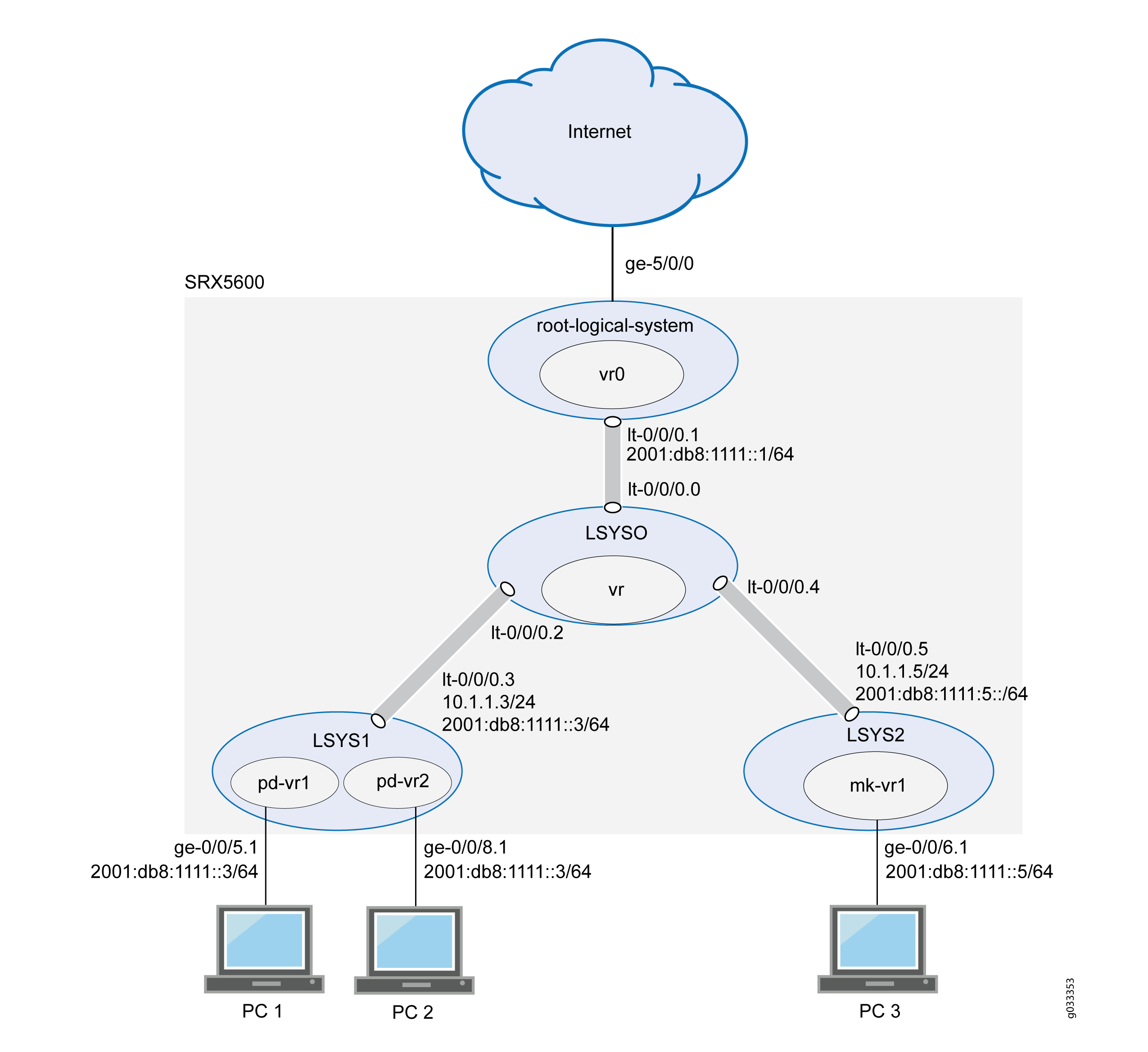
This scenario shows how to configure interfaces for the logical systems on the device, including an interconnect logical system.
-
For the interconnect logical system, the example configures logical tunnel interfaces lt-0/0/0.0, lt-0/0/0.2, and lt-0/0/0.4. The example configures a routing instance called vr and assigns the interfaces to it.
Because the interconnect logical system acts as a virtual switch, it is configured as a VPLS routing instance type. The interconnect logical system’s lt-0/0/0 interfaces are configured with ethernet-vpls as the encapsulation type. The corresponding peer lt-0/0/0 interfaces in the primary and user logical systems are configured with Ethernet as the encapsulation type.
-
lt-0/0/0.0 connects to lt-0/0/0.1 on the root logical system.
-
lt-0/0/0.2 connects to lt-0/0/0.3 on the LSYS1 logical system.
-
lt-0/0/0.4 connects to lt-0/0/0.5 on the LSYS2 logical system.
-
-
For the primary logical system, called root-logical-system, the example configures ge-5/0/0 and assigns it to the vr0 routing instance. The example configures lt-0/0/0.1 to connect to lt-0/0/0.0 on the interconnect logical system and assigns it to the vr0 routing instance. The example configures static routes to allow for communication with other logical systems and assigns them to the vr0 routing instance.
-
For the LSYS1 logical system, the example configures lt-0/0/0.3 to connect to lt-0/0/0.2 on the interconnect logical system.
-
For the LSYS2 logical system, the example configures lt-0/0/0.5 to connect to lt-0/0/0.4 on the interconnect logical system.
Figure 1 shows the topology for this deployment including virtual routers and their interfaces for all IPv6 logical systems.
Topology
Configuration
This topic explains how to configure interfaces for logical systems.
- Configuring Logical Tunnel Interfaces and a Routing Instance for the Interconnect Logical System
- Configuring Interfaces, a Routing Instance, and Static Routes for the Primary Logical System
- Configuring Logical Tunnel Interfaces for the User Logical Systems
Configuring Logical Tunnel Interfaces and a Routing Instance for the Interconnect Logical System
CLI Quick Configuration
To quickly configure this example, copy the following commands, paste them
into a text file, remove any line breaks, change any details necessary to
match your network configuration, copy and paste the commands into the CLI
at the [edit] hierarchy level, and then enter
commit from configuration mode.
set forwarding-options family inet6 mode flow-based
set logical-systems LSYS0 interfaces lt-0/0/0 unit 0 encapsulation ethernet-vpls
set logical-systems LSYS0 interfaces lt-0/0/0 unit 0 peer-unit 1
set logical-systems LSYS0 interfaces lt-0/0/0 unit 2 encapsulation ethernet-vpls
set logical-systems LSYS0 interfaces lt-0/0/0 unit 2 peer-unit 3
set logical-systems LSYS0 interfaces lt-0/0/0 unit 4 encapsulation ethernet-vpls
set logical-systems LSYS0 interfaces lt-0/0/0 unit 4 peer-unit 5
set logical-systems LSYS0 routing-instances vr instance-type vpls
set logical-systems LSYS0 routing-instances vr interface lt-0/0/0.0
set logical-systems LSYS0 routing-instances vr interface lt-0/0/0.2
set logical-systems LSYS0 routing-instances vr interface lt-0/0/0.4
Step-by-Step Procedure
The following example requires you to navigate various levels in the configuration hierarchy. For instructions on how to do that, see Using the CLI Editor in Configuration Mode in the Junos OS CLI User Guide.
To configure the interconnect system lt-0/0/0 interfaces and routing instances:
-
Enable flow-based forwarding for IPv6 traffic.
[edit security] user@host# set forwarding-options family inet6 mode flow-based -
Configure the lt-0/0/0 interfaces.
[edit logical-systems LSYS0 interfaces]
user@host# set lt-0/0/0 unit 0 encapsulation ethernet-vpls
user@host# set lt-0/0/0 unit 0 peer-unit 1
user@host# set lt-0/0/0 unit 2 encapsulation ethernet-vpls
user@host# set lt-0/0/0 unit 2 peer-unit 3
user@host# set lt-0/0/0 unit 4 encapsulation ethernet-vpls
user@host# set lt-0/0/0 unit 4 peer-unit 5
-
Configure the routing instance for the interconnect logical system and add its lt-0/0/0 interfaces to it.
[edit logical-systems LSYS0 routing-instances]
user@host# set vr instance-type vpls
user@host# set vr interface lt-0/0/0.0
user@host# set vr interface lt-0/0/0.2
user@host# set vr interface lt-0/0/0.4
Results
From configuration mode, confirm your configuration by entering the
show logical-systems interconnect-logical-system command. If
the output does not display the intended configuration, repeat the
instructions in this example to correct the configuration.
If you are done configuring the device, enter commit from
configuration mode.
user@host# show logical-systems LSYS0
interfaces {
    lt-0/0/0 {
        unit 0 {
            encapsulation ethernet-vpls;
            peer-unit 1;
        }
        unit 2 {
            encapsulation ethernet-vpls;
            peer-unit 3;
            }
            unit 4 {
                encapsulation ethernet-vpls;
                peer-unit 5;
            }
        }
    }
        routing-instances {
            vr {
                instance-type vpls;
                interface lt-0/0/0.0;
                interface lt-0/0/0.2;
                interface lt-0/0/0.4;
            }
        }
Configuring Interfaces, a Routing Instance, and Static Routes for the Primary Logical System
CLI Quick Configuration
To quickly configure this example, copy the following commands, paste them
into a text file, remove any line breaks, change any details necessary to
match your network configuration, copy and paste the commands into the CLI
at the [edit] hierarchy level, and then enter
commit from configuration mode.
set interfaces ge-5/0/0 vlan-taggingset interfaces ge-5/0/0 unit 0 vlan-id 600set interfaces lt-0/0/0 unit 1 encapsulation Ethernetset interfaces lt-0/0/0 unit 1 peer-unit 0set interfaces lt-0/0/0 unit 1 family inet address 10.1.1.1/24set interfaces lt-0/0/0 unit 1 family inet6 address 2001:db8:1111::1/64set interfaces ge-5/0/0 unit 0 family inet address 10.99.99.1/24set interfaces ge-5/0/0 unit 0 family inet6 address 2001:db8:9999::1/64set routing-instances vr0 instance-type virtual-routerset routing-instances vr0 interface lt-0/0/0.1set routing-instances vr0 interface ge-5/0/0.0set routing-instances vr0 routing-options rib vr0.inet6.0 static route 2001:db8:777::/64 next-hop 2001:db8:1111::3set routing-instances vr0 routing-options rib vr0.inet6.0 static route 2001:db8:888::/64 next-hop 2001:db8:1111::3set routing-instances vr0 routing-options rib vr0.inet6.0 static route 2001:db8:666::/64 next-hop 2001:db8:1111::5set routing-instances vr0 routing-options static route 192.168.7.0/24 next-hop 10.1.1.3set routing-instances vr0 routing-options static route 192.168.8.0/24 next-hop 10.1.1.3set routing-instances vr0 routing-options static route 192.168.6.0/24 next-hop 10.1.1.5
Step-by-Step Procedure
The following example requires you to navigate various levels in the configuration hierarchy. For instructions on how to do that, see Using the CLI Editor in Configuration Mode.
To configure the primary logical system interfaces:
-
Configure the primary (root) logical system and lt-0/0/0.1 interfaces.
[edit interfaces] user@host#
set ge-5/0/0 vlan-tagginguser@host#set ge-5/0/0 unit 0 vlan-id 600user@host#set lt-0/0/0 unit 1 encapsulation Ethernetuser@host#set lt-0/0/0 unit 1 peer-unit 0user@host#set lt-0/0/0 unit 1 family inet address 10.1.1.1/24user@host#set lt-0/0/0 unit 1 family inet6 address 2001:db8:1111::1/64user@host#set ge-5/0/0 unit 0 family inet address 10.99.99.1/24user@host#set ge-5/0/0 unit 0 family inet6 address 2001:db8:9999::1/64 -
Configure a routing instance for the primary logical system, assign its interfaces to it, and configure static routes for it.
[edit interfaces routing-instances] user@host#
set vr0 instance-type virtual-routeruser@host#set vr0 interface lt-0/0/0.1user@host#set vr0 interface ge-5/0/0.0user@host#set vr0 routing-options rib vr0.inet6.0 static route 2001:db8:1111:777/64 next-hop 2001:db8:1111::3user@host#set vr0 routing-options rib vr0.inet6.0 static route 2001:db8:1111:888/64 next-hop 2001:db8:1111::3user@host#set vr0 routing-options rib vr0.inet6.0 static route 2001:db8:1111:666/64 next-hop 2001:db8:1111::5user@host#set vr0 routing-options static route 192.168.7.0/24 next-hop 10.1.1.3user@host#set vr0 routing-options static route 192.168.8.0/24 next-hop 10.1.1.3user@host#set vr0 routing-options static route 192.168.6.0/24 next-hop 10.1.1.5
Results
From configuration mode, confirm your configuration by entering the
show interfaces and show
routing-instances commands. If the output does not display the
intended configuration, repeat the instructions in this example to correct
the configuration.
[edit]
user@host# show interfaces
ge-5/0/0 {
    vlan-tagging;
    unit 0 {
        vlan-id 600;
        family inet {
            address 10.99.99.1/24;
        }
        family inet 6{
            address 2001:db8:9999:1/64;
        }
    }
}
lt-0/0/0 {
    unit 1 {
        encapsulation ethernet;
        peer-unit 0;
        family inet {
            address 10.1.1.1/24;
        }
        family inet 6{
            address 2001:db8:1111::1/64;
        }
    }
}
[edit]
user@host# show routing-instances
vr0 {
    instance-type virtual-router;
    interface ge-5/0/0.0;
    interface lt-0/0/0;
    routing-options {
        rib vr0.inet6.0 {
        static {
            route 2001:db8:1111:888/64 next-hop 2001:db8:1111:3;
            route 2001:db8:1111:777/64 next-hop 2001:db8:1111:3;
            route 2001:db8:1111:666/64 next-hop 2001:db8:1111:5;
        }
        }
        static {
            route 192.168.7.0/24 next-hop 10.1.1.3;
            route 192.168.8.0/24 next-hop 10.1.1.3;
            route 192.168.6.0/24 next-hop 10.1.1.5;
        }
    }
}
If you are done configuring the device, enter commit from
configuration mode.
Configuring Logical Tunnel Interfaces for the User Logical Systems
CLI Quick Configuration
To quickly configure this example, copy the following commands, paste them
into a text file, remove any line breaks, change any details necessary to
match your network configuration, copy and paste the commands into the CLI
at the [edit] hierarchy level, and then enter
commit from configuration mode.
set logical-systems LSYS1 interfaces lt-0/0/0 unit 3 encapsulation ethernetset logical-systems LSYS1 interfaces lt-0/0/0 unit 3 peer-unit 2set logical-systems LSYS1 interfaces lt-0/0/0 unit 3 family inet address 10.1.1.3/24set logical-systems LSYS1 interfaces lt-0/0/0 unit 3 family inet6 address 2001:db8:1111:2/64set logical-systems LSYS2 interfaces lt-0/0/0 unit 5 encapsulation ethernetset logical-systems LSYS2 interfaces lt-0/0/0 unit 5 peer-unit 4set logical-systems LSYS2 interfaces lt-0/0/0 unit 5 family inet address 10.1.1.5/24set logical-systems LSYS2 interfaces lt-0/0/0 unit 5 family inet6 address 2001:db8:1111::5/64
Step-by-Step Procedure
The following example requires you to navigate various levels in the configuration hierarchy. For instructions on how to do that, see Using the CLI Editor in Configuration Mode.
-
Configure the lt-0/0/0 interface for the first user logical system:
[edit logical-systems LSYS1 interfaces lt-0/0/0 unit 3] user@host#
set encapsulation ethernetuser@host#set peer-unit 2user@host#set family inet address 10.1.1.3/24user@host#set family inet6 address 2001:db8:1111:3::1/64 -
Configure the lt-0/0/0 interface for the second user logical system.
[edit logical-systems LSYS2 interfaces lt-0/0/0 unit 5] user@host#
set encapsulation ethernetuser@host#set peer-unit 4user@host#set family inet address 10.1.1.5/24user@host#set family inet6 address 2001:db8:1111::5/64
Results
From configuration mode, confirm your configuration by entering the
show logical-systems LSYS1 interfaces lt-0/0/0, and
show logical-systems LSYS2 interfaces lt-0/0/0
commands. If the output does not display the intended configuration, repeat
the instructions in this example to correct the configuration.
user@host# show logical-systems LSYS1 interfaces lt-0/0/0
lt-0/0/0 {
    unit 3 {
        encapsulation ethernet;
        peer-unit 2;
        family inet {
            address 10.1.1.3/24;
        }
        family inet 6{
            address 2001:db8:1111::3/64;
        }
    }
}
user@host# show logical-systems LSYS2 interfaces lt-0/0/0
lt-0/0/0 {
    unit 5 {
        encapsulation ethernet;
        peer-unit 4;
        family inet {
            address 10.1.1.5/24;
        }
        family inet 6{
            address 2001:db8:1111::5/64;
        }
    }
}
If you are done configuring the device, enter commit from
configuration mode.
Verification
Verifying That the Static Routes Configured for the Primary Administrator Are Correct
Purpose
Confirm that the configuration is working properly. Verify if you can send data from the primary logical system to the other logical systems.
Action
From operational mode, use the ping command.
Example: Configuring IPv6 Zones for a User Logical Systems
This example shows how to configure IPv6 zones for a user logical system.
Requirements
Before you begin:
Log in to the user logical system as the user logical system administrator.
Ensure that forwarding options for inet6 is flow-based. Otherwise, you must configure it and reset the device.
Use the
show security forwarding-optionscommand to check the configuration.Note:Only the user logical system administrator can configure the forwarding options.
Overview
This example configures the ls-product-design user logical system described in Example: Creating User Logical Systems, Their Administrators, Their Users, and an Interconnect Logical System
This example creates the IPv6 zones and address books described in Table 1.
Feature |
Name |
Configuration Parameters |
|---|---|---|
Zones |
ls-product-design-trust |
|
ls-product-design-untrust |
|
|
Address books |
product-design-internal |
|
product-design-external |
|
Configuration
Procedure
CLI Quick Configuration
To quickly configure this example, copy the
following commands, paste them into a text file, remove any line breaks,
change any details necessary to match your network configuration,
copy and paste the commands into the CLI at the [edit] hierarchy
level, and then enter commit from configuration mode.
set logical-system lsys1 security address-book product-design-internal address product-designers 3002::1/96
set logical-system lsys1 security address-book product-design-internal attach zone ls-product-design-trust
set logical-system lsys1 security address-book product-design-external address marketing 3003::1/24
set logical-system lsys1 security address-book product-design-external address accounting 3004::1/24
set logical-system lsys1 security address-book product-design-external address others 3002::2/24
set logical-system lsys1 security address-book product-design-external address-set otherlsys address marketing
set logical-system lsys1 security address-book product-design-external address-set otherlsys address accounting
set logical-system lsys1 security address-book product-design-external attach zone ls-product-design-untrust
set logical-system lsys1 security zones security-zone ls-product-design-trust tcp-rst
set logical-system lsys1 security zones security-zone ls-product-design-trust interfaces ge-0/0/5.1
set logical-system lsys1 security zones security-zone ls-product-design-untrust interfaces lt-0/0/0.3
Step-by-Step Procedure
The following example requires you to navigate various levels in the configuration hierarchy. For instructions on how to do that, see Using the CLI Editor in Configuration Mode in the Junos OS CLI User Guide.
To configure IPv6 zones in a user logical system:
Log in to the user logical system as the logical system administrator and enter configuration mode.
lsdesignadmin1@host:ls-product-design> configure
lsdesignadmin1@host:ls-product-design#
Configure a security zone and assign it to an interface.
[edit logical-system lsys1 security zones]
lsdesignadmin1@host:ls-product-design# set security-zone ls-product-design-trust interfaces ge-0/0/5.1
Configure the TCP-Reset parameter for the zone.
[edit logical-system lsys1 security zones security-zone ls-product-design-trust]
lsdesignadmin1@host:ls-product-design#  set tcp-rst
Configure a security zone and assign it to an interface.
[edit logical-system lsys1 security zones]
lsdesignadmin1@host:ls-product-design# set security-zone ls-product-design-untrust interfaces lt-0/0/0.3
Create global address book entries.
[edit logical-system lsys1 security]
lsdesignadmin1@host:ls-product-design# set address-book product-design-internal address product-designers 3002::1/96
lsdesignadmin1@host:ls-product-design# set address-book product-design-external address marketing 3003::1/24
lsdesignadmin1@host:ls-product-design# set address-book product-design-external address accounting 3004::1/24
lsdesignadmin1@host:ls-product-design# set address-book product-design-external address others 3002::2/24
lsdesignadmin1@host:ls-product-design# set address-book product-design-external address-set otherlsys address marketing
lsdesignadmin1@host:ls-product-design# set address-book product-design-external address-set otherlsys address accounting
Attach address books to zones.
[edit logical-system lsys1 security]
lsdesignadmin1@host:ls-product-design#set address-book product-design-internal attach zone ls-product-design-trust
lsdesignadmin1@host:ls-product-design#set address-book product-design-external attach zone ls-product-design-untrust
Results
From configuration mode, confirm your configuration
by entering the show security zones command. If the output
does not display the intended configuration, repeat the configuration
instructions in this example to correct it.
lsdesignadmin1@host:ls-product-design# show security zones
address-book {
    product-design-internal {
        address product-designers 3002::1/96;
        attach {
            zone ls-product-design-trust;
        }
    }
    product-design-external {
        address marketing 3003::1/24;
        address accounting 3004::1/24;
        address others 3002::2/24;
        address-set otherlsys {
            address marketing;
            address accounting;
        }
        attach {
            zone ls-product-design-untrust;
        }
    }
}
zones {
    security-zone ls-product-design-trust {
        tcp-rst;
        interfaces {
            ge-0/0/5.1;
        }
    }
    security-zone ls-product-design-untrust {
        interfaces {
            lt-0/0/0.3;
        }
    }
}
If you are done configuring the device, enter commit from configuration mode.
Example: Configuring IPv6 Security Policies for a User Logical Systems
This example shows how to configure IPv6 security policies for a user logical system.
Requirements
Before you begin:
Log in to the user logical system as the logical system administrator.
Use the
show system security-profiles policycommand to see the security policy resources allocated to the logical system.Configure zones and address books.
See Example: Configuring IPv6 Zones for a User Logical Systems
Overview
This example shows how to configure the security policies described in Table 2.
Policy Name |
Configuration Parameters |
|---|---|
permit-all-to-otherlsys |
Permit the following traffic:
|
permit-all-from-otherlsys |
Permit the following traffic:
|
Configuration
Procedure
CLI Quick Configuration
To quickly configure this example, copy the
following commands, paste them into a text file, remove any line breaks,
change any details necessary to match your network configuration,
copy and paste the commands into the CLI at the [edit] hierarchy
level, and then enter commit from configuration mode.
set logical-systems lsys1 security policies from-zone ls-product-design-trust to-zone ls-product-design-untrust policy permit-all-to-otherlsys match source-address product-designers
set logical-systems lsys1 security policies from-zone ls-product-design-trust to-zone ls-product-design-untrust policy permit-all-to-otherlsys match destination-address otherlsys
set logical-systems lsys1 security policies from-zone ls-product-design-trust to-zone ls-product-design-untrust policy permit-all-to-otherlsys match application any
set logical-systems lsys1 security policies from-zone ls-product-design-trust to-zone ls-product-design-untrust policy permit-all-to-otherlsys then permit
set logical-systems lsys1 security policies from-zone ls-product-design-untrust to-zone ls-product-design-trust policy permit-all-from-otherlsys match source-address otherlsys
set logical-systems lsys1 security policies from-zone ls-product-design-untrust to-zone ls-product-design-trust policy permit-all-from-otherlsys match destination-address product-designers
set logical-systems lsys1 security policies from-zone ls-product-design-untrust to-zone ls-product-design-trust policy permit-all-from-otherlsys match application any
set logical-systems lsys1 security policies from-zone ls-product-design-untrust to-zone ls-product-d esign-trust policy permit-all-from-otherlsys then permit
Step-by-Step Procedure
The following example requires you to navigate various levels in the configuration hierarchy. For instructions on how to do that, see Using the CLI Editor in Configuration Mode in the Junos OS CLI User Guide.
To configure IPv6 security policies for a user logical system:
Log in to the user logical system as the logical system administrator and enter configuration mode.
lsdesignadmin1@host:ls-product-design> configure
lsdesignadmin1@host:ls-product-design#
Configure a security policy that permits traffic from the ls-product-design-trust zone to the ls-product-design-untrust zone.
[edit logical-systems lsys1 security policies from-zone ls-product-design-trust to-zone ls-product-design-untrust]
lsdesignadmin1@host:ls-product-design# set policy permit-all-to-otherlsys match source-address product-designers
lsdesignadmin1@host:ls-product-design# set policy permit-all-to-otherlsys match destination-address otherlsys
lsdesignadmin1@host:ls-product-design# set policy permit-all-to-otherlsys match application any
lsdesignadmin1@host:ls-product-design# set policy permit-all-to-otherlsys then permit
Configure a security policy that permits traffic from the ls-product-design-untrust zone to the ls-product-design-trust zone.
[edit logical-systems lsys1 security policies from-zone ls-product-design-untrust to-zone ls-product-design-trust]
lsdesignadmin1@host:ls-product-design# set policy permit-all-from-otherlsys match source-address otherlsys
lsdesignadmin1@host:ls-product-design# set policy permit-all-from-otherlsys match destination-address product-designers
lsdesignadmin1@host:ls-product-design# set policy permit-all-from-otherlsys match application any
lsdesignadmin1@host:ls-product-design# set policy permit-all-from-otherlsys then permit
Results
From configuration mode, confirm your configuration
by entering the show security policies command. If the
output does not display the intended configuration, repeat the configuration
instructions in this example to correct it.
lsdesignadmin1@host:ls-product-design# show security policies
from-zone ls-product-design-trust to-zone ls-product-design-untrust {
    policy permit-all-to-otherlsys {
        match {
            source-address product-designers;
            destination-address otherlsys;
            application any;
        }
        then {
            permit;
        }
    }
}
from-zone ls-product-design-untrust to-zone ls-product-design-trust {
    policy permit-all-from-otherlsys {
        match {
            source-address otherlsys;
            destination-address product-designers;
            application any;
        }
        then {
            permit;
        }
    }
}
If you are done configuring the device, enter commit from configuration mode.
Example: Configuring IPv6 Dual-Stack Lite for a User Logical Systems
This example shows how to configure a softwire concentrator for a user logical system.
Requirements
Before you begin:
Log in to the user logical system as the user logical system administrator. See User Logical Systems Configuration Overview.
Use the
show system security-profile dslite-softwire-initiatorcommand to see the number softwire initiators that can be connected to a softwire concentrator in the logical system.
Overview
This example shows how to configure a softwire concentrator to decapsulate IPv4-in-IPv6 packets in the ls-product-design user logical system shown in Example: Creating User Logical Systems, Their Administrators, Their Users, and an Interconnect Logical System. The IPv6 address of the softwire concentrator is 3000::1 and the name of the softwire configuration is sc_1.
Configuration
Procedure
CLI Quick Configuration
To quickly configure this example, copy the
following commands, paste them into a text file, remove any line breaks,
change any details necessary to match your network configuration,
copy and paste the commands into the CLI at the [edit] hierarchy
level, and then enter commit from configuration mode.
set security softwires softwire-name sc_1 softwire-concentrator 3000::1 softwire-type IPv4-in-IPv6
Step-by-Step Procedure
The following example requires you to navigate various levels in the configuration hierarchy. For instructions on how to do that, see Using the CLI Editor in Configuration Mode in the Junos OS CLI User Guide.
To configure an IPv6 DS-Lite softwire concentrator:
Log in to the user logical system as the logical system administrator and enter configuration mode.
lsdesignadmin1@host:ls-product-design> configure
lsdesignadmin1@host:ls-product-design#
Specify the address of the softwire concentrator and the softwire type.
[edit security]
lsdesignadmin1@host:ls-product-design# set softwires softwire-name sc_1 softwire-concentrator 3000::1 softwire-type IPv4-in-IPv6
Results
From configuration mode, confirm your configuration
by entering the show security softwires command. If the
output does not display the intended configuration, repeat the configuration
instructions in this example to correct it.
[edit]
lsdesignadmin1@host:ls-product-design# show security softwires
softwire-name sc_1 {
    softwire-concentrator 3000::1;
    softwire-type IPv4-in-IPv6;
}
If you are done configuring the device, enter commit from configuration mode.
Verification
Verifying the DS-Lite Configuration
Purpose
Verify that the softwire initiators can connect to the softwire concentrator configured in the user logical system.
Action
From operational mode, enter the show security
softwires command.
If a softwire initiator is not connected, the operational output looks like this:
lsdesignadmin1@host:ls-product-design> show security softwires
Softwire Name            SC Address         Status   Number of SI connected
  sc_1                      3000::1         Active         0
If a softwire initiator is connected, the operational output looks like this:
lsdesignadmin1@host:ls-product-design> show security softwires
Softwire Name            SC Address         Status   Number of SI connected
  sc_1                      3000::1         Connected      1