ON THIS PAGE
EVPN-VXLAN DCI Multicast with Enhanced OISM
Transfer IPv4 or IPv6 multicast traffic efficiently and seamlessly across EVPN-VXLAN to EVPN-VXLAN interconnected data centers using enhanced OISM.
We support efficient transfer of IPv4 or IPv6 multicast traffic with Ethernet VPN–Virtual Extensible LAN (EVPN-VXLAN) to EVPN-VXLAN seamless data center interconnect (DCI) stitching using enhanced optimized intersubnet multicast (OISM). The EVPN-VXLAN fabrics on both sides of the interconnection can use either IPv4 underlay peering or IPv6 underlay peering.
Without this feature, the DCI gateway (iGW) devices in each data center flood multicast traffic across the WAN. Flooding consumes significant WAN bandwidth if your network has many multicast flows or high multicast traffic rates. This feature seamlessly replaces the multicast flooding behavior in DCI stitched networks to optimize multicast forwarding across the DCI.
Benefits of DCI Multicast with Enhanced OISM
Significantly reduces network bandwidth consumption when transferring multicast traffic across the WAN interconnecting data centers, especially if your network has a large number of multicast flows or high multicast traffic rates.
Prevents traffic loss when the designated forwarder (DF) and non-DF (NDF) status changes among the multihomed iGW devices that share an interconnect Ethernet segment (I-ESI) in a data center.
EVPN-VXLAN to EVPN-VXLAN DCI Stitching Overview
DCI stitching seamlessly transfers control and data traffic in EVPN-VXLAN data centers across an interconnecting WAN. See Figure 1. DCI gateway (iGW) devices in each data center use different route targets (RTs) for:
Traffic inside the data center (DC-1 RT, DC-2 RT).
Traffic exchanged across the WAN (WAN RT).
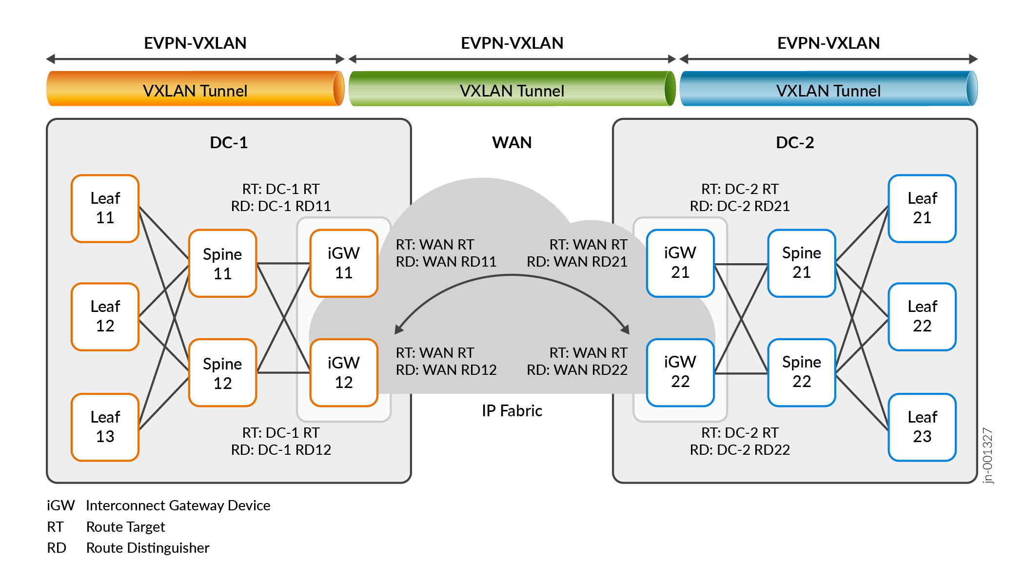
To configure iGW devices, you use the interconnect stanza at the [edit <routing-instances routing-instance-name> protocols evpn] hierarchy level. Also see the following for some DCI configuration examples:
OISM Overview
OISM handles multicast traffic efficiently in an EVPN-VXLAN data center for multicast sources and receivers inside and outside the data center.
OISM has two modes:
Regular OISM mode—This mode uses a symmetric bridge domains OISM model that requires you to configure all revenue VLANs (the tenant VLANs) in the network on all OISM leaf devices. This is the original OISM implementation.
Enhanced OISM mode—This mode doesn't require you to configure all revenue bridge domains (VLANs) in the network on all OISM devices. On each device, you can configure only the revenue VLANs hosted by that device (so we call this an asymmetric model). However, you must still configure the revenue VLANs symmetrically on OISM devices that are multihoming peers.
We support this seamless optimized multicast over DCI feature with enhanced OISM only.
OISM operates on the server leaf and border leaf provider edge (PE) devices in EVPN-VXLAN edge-routed bridging (ERB) overlay data center architectures. If the topology includes a layer of transit spine devices, you don't configure OISM on those devices.
OISM server leaf devices host the multicast sources and receivers within the data center. The sources and receivers can be either directly connected or connected through intermediary customer edge (CE) devices.
OISM border leaf devices connect to external multicast domains to transfer multicast data into a data center from external sources and out of a data center to external receivers. Like server leaf devices, the border leaf devices might also host devices in the data center that are multicast sources or receivers.
See Optimized Intersubnet Multicast (OISM) in EVPN Networks for details on how OISM works in general. See these sections for more on the differences with enhanced OISM operation in particular:
OISM Configuration
In regular or enhanced mode, OISM requires many configuration elements to operate. You configure some elements in common on server leaf devices and border leaf devices. Some elements are specific to OISM server leaf devices or border leaf devices. See the configuration sections in Optimized Intersubnet Multicast (OISM) in EVPN Networks for the steps to configure each type of OISM device. Many of the configuration steps are the same for either regular or enhanced OISM modes.
You can configure iGW devices to act as enhanced OISM server leaf or border leaf devices. If the iGW devices also provide the interfaces to external multicast sources or receivers, you configure them as OISM border leaf devices.
OISM Supplemental Bridge Domain (SBD)
One common configured element for OISM operation is the VLAN called the supplemental bridge domain (SBD). You configure a unique SBD VLAN ID and corresponding integrated routing and bridging (IRB) interface for each tenant virtual routing and forwarding (VRF) instance in a data center.
One major difference between regular OISM and enhanced OISM is that regular OISM ingress devices send multicast traffic from the source on the source VLAN to other OISM devices. In contrast, enhanced OISM ingress devices send source traffic on the source VLAN only to their multihoming peers, and use the SBD to send source traffic to all other OISM devices.
When you use enhanced OISM with DCI stitching, you assign the same VLAN as the SBD in both data centers for the VRF instances that span the interconnection. The iGW devices with enhanced OISM enabled transfer multicast control and data traffic across the interconnection only on the SBD.
Because enhanced OISM uses the SBD toward remote devices that aren't its multihoming peers, the enhanced mode has an inherent limitation where packets with TTL=1 will not reach receivers on those remote devices.
If you use enhanced OISM with DCI stitching and need to avoid this limitation, we have a solution that enables enhanced OISM to behave like regular OISM to use the source VLAN for particular multicast data flows toward the remote OISM devices. You can enable this solution for particular multicast groups (or groups and sources) using routing policies and the forward-on-source-bridge-domain configuration option. See Enhanced OISM Exception Policy to Forward on Source VLAN Instead of SBD for Packets with TTL=1 for details.
How Enhanced OISM Works over DCI Stitching
In a DCI stitching environment without enhanced OISM, the iGW devices default to flooding all multicast traffic across the interconnecting WAN. Flooding can consume significant WAN bandwidth when you have heavy multicast traffic loads.
This feature seamlessly replaces the multicast flooding behavior across the WAN with selective multicast Ethernet tag (SMET) forwarding between the data centers. SMET forwarding only sends multicast traffic across the interconnection when the other data center has receivers that explicitly subscribed to that multicast flow. EVPN Type 6 routes implement SMET in EVPN data centers.
You enable enhanced OISM on the leaf devices in each data center as either OISM server leaf devices or OISM border leaf devices. The DCI iGW devices can be either type of OISM leaf device. Often, the iGW devices are the devices in the EVPN-VXLAN fabric that also act as the OISM border leaf devices to connect to external sources or receivers.
In the figures in this section and the following sections showing DCI with enhanced OISM, the spine devices in the DCI architecture in Figure 1 act only as L3 transit devices in each data center. You don't configure OISM on the spine devices. As a result, to more clearly show how the multicast control and data traffic flows among the OISM leaf devices, we don't include the spine devices in these figures.
- SMET (EVPN Type 6 Route) Control Flow Across DCI
- Multicast Data Flow with SMET and Enhanced OISM Across DCI
SMET (EVPN Type 6 Route) Control Flow Across DCI
Figure 2 shows the control flow for EVPN Type 6 routes in each data center and across the interconnection.

The SMET control flow operates as follows:
To subscribe to a multicast data flow, a receiver in DC-2, for example, sends an Internet Group Management Protocol (IGMP) report for IPv4 multicast flows, or sends a Multicast Listener Discovery (MLD) report for IPv6 multicast flows.
The OISM leaf device that receives the IGMP or MLD report in DC-2, Leaf 21 in this case, creates a SMET route (EVPN Type 6 route) for that subscription. The SMET route uses the RT for DC-2.
Leaf 21 advertises the route on the OISM SBD to all other OISM leaf devices in DC-2 (Leaf 22, Leaf 23, iGW 21, and iGW 22).
The iGW devices configured as OISM leaf devices in DC-2 (iGW 21, and iGW 22) receive the SMET route on the SBD, seamlessly re-originate the SMET route using the WAN RT, and forward the SMET route on the OISM SBD across the DCI.
The iGW devices on the other side of the DCI in DC-1 (iGW 11 and iGW 12) receive the SMET route with the WAN RT on the SBD. iGW 11 and iGW 12 seamlessly re-originate the SMET route using the RT for DC-1, and forward the SMET route to all other OISM leaf devices in DC-1.
The OISM leaf devices in both data centers store the multicast subscriber information from the SMET routes in their multicast routing and forwarding tables.
Multicast Data Flow with SMET and Enhanced OISM Across DCI
Figure 3 shows that based on received SMET routes, the OISM leaf devices in each data center send multicast traffic from the source only to the remote receivers across the DCI who subscribed to that multicast flow.
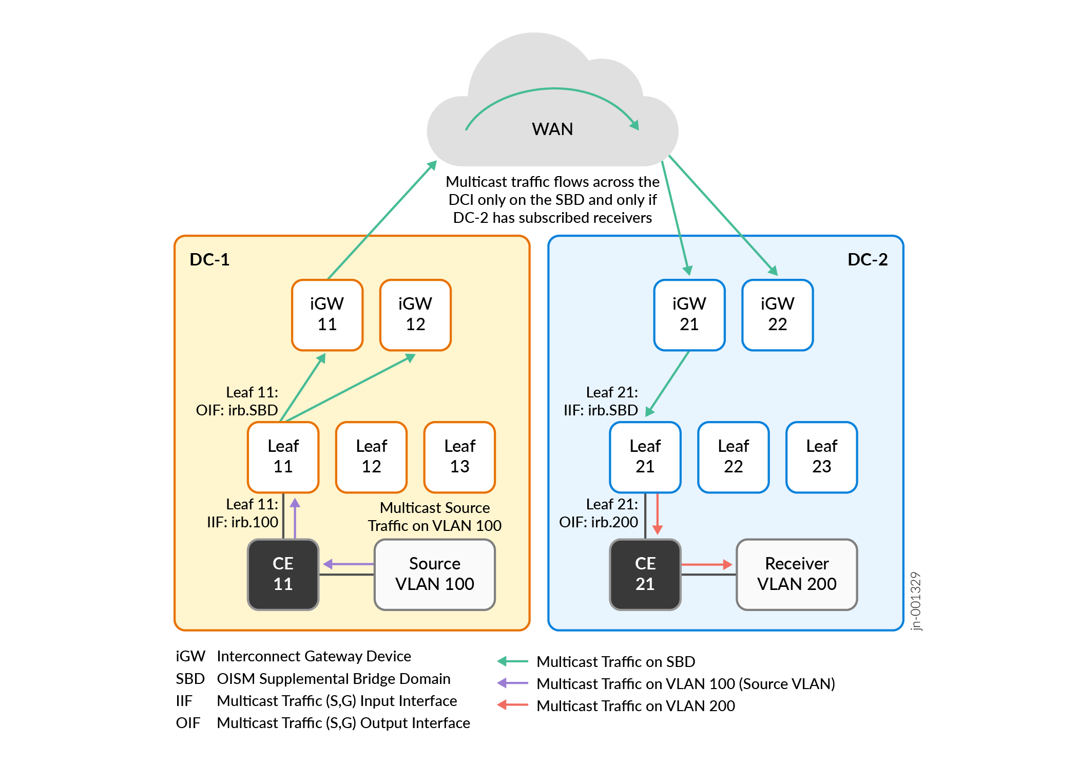
In this case:
The multicast source is in DC-1 on VLAN 100.
A receiver in DC-2 on VLAN 200 subscribes to the multicast data from the source in DC-1.
As we show in SMET (EVPN Type 6 Route) Control Flow Across DCI, the OISM leaf devices in both data centers, including iGW 11, iGW 12, and Leaf 11 in DC-1, receive SMET routes for that subscription.
In DC-1, Leaf 11 receives multicast traffic from the source on VLAN 100. Leaf 11 knows from receiving the SMET routes that there is a receiver in DC-2, so Leaf 11 routes the multicast traffic to iGW 11 and iGW 12 on the SBD.
Note:Although Figure 3 doesn't show local receivers on the other leaf devices in DC-1, Leaf 11 would also route the multicast traffic on the SBD to those devices if (and only if) those devices also have subscribed receivers.
iGW 11 and iGW 12 also know from receiving the SMET routes that there is a receiver in DC-2. In this case, iGW 11 is the DF for the pair of iGW devices in DC-1. So iGW 11 forwards the traffic over the interconnection to DC-2 on the SBD.
The iGW devices in DC-2 receive the multicast traffic. In this case, iGW 21 is the DF for the pair of iGW devices in DC-2, so iGW 21 forwards the traffic on the SBD to Leaf 21 toward the subscribed receiver.
In DC-2, Leaf 21 routes the multicast traffic toward the receiver on the receiver VLAN, VLAN 200.
See Multicast Next Hops Convergence Optimization for more on how we improve EVPN multicast next hop convergence over the DCI when iGW device DF and NDF status changes.
More Enhanced OISM over DCI Use Cases
We support a variety of configurations for DCI multicast with enhanced OISM.
For example, the multicast source can be:
- Behind an OISM server leaf device in one of the data centers.
Multicast Data Flow with SMET and Enhanced OISM Across DCI describes a use case with an internal source behind an OISM server leaf device in one data center to subscribed receivers behind OISM server leaf devices in another data center.
Multicast Traffic Flow across DCI from Multihomed Source on DCI Gateway Devices describes a use case with an internal source that is multihomed to the iGW devices acting as OISM server leaf devices in one data center. The receivers are behind OISM leaf devices in both data centers.
- In an external PIM domain connected to the iGW devices in one of the data centers.
Multicast Traffic Flow from External Source to Internal Receivers describes a use case where the iGW devices also act as the OISM PIM EVPN gateway (PEG) devices. The receivers are inside both of the interconnected data centers.
In an external PIM domain connected to an OISM leaf device or multihomed to more than one OISM leaf device in one of the data centers.
In this use case, you configure those leaf devices as the OISM border leaf PEG devices. We don't include a figure or describe this use case in detail here.
With a multicast source in one of the data centers, the multicast receivers can be:
In the same data center as the multicast source, or in another data center across the DCI.
Multicast Traffic Flow across DCI from Multihomed Source on DCI Gateway Devices describes a use case where the source is multihomed to the iGW devices in one data center and the receivers are behind OISM leaf devices in both data centers.
In an external PIM domain where the PIM router is connected to OISM PEG devices in either data center.
Multicast Control and Data Flow for Internal Source to External Receiver describes a use case where the source is behind an OISM server leaf devices in one data center. The external PIM domain connected to that data center has an external receiver, and both interconnected data centers also have internal receivers.
We show some of these additional use cases in the next sections.
- Multicast Traffic Flow across DCI from Multihomed Source on DCI Gateway Devices
- Multicast Traffic Flow from External Source to Internal Receivers
- Multicast Control and Data Flow for Internal Source to External Receiver
Multicast Traffic Flow across DCI from Multihomed Source on DCI Gateway Devices
Figure 4 shows a use case where the multicast source on VLAN 100 is multihomed to iGW 11 and iGW 12 in DC-1. You configure all of the leaf devices in this use case as OISM server leaf devices because all sources and receivers are inside the interconnected data centers.
Both of the interconnected data centers have internal subscribed receivers behind the following OISM server leaf devices:
In DC-1: Leaf 11, Leaf 13, and iGW 12
In DC-2: Leaf 21
The multihoming peer iGW devices in each data center elect a DF; the other iGW devices become NDFs (also called backup DFs [BDFs]). The DF forwards or routes multicast source traffic to the other OISM leaf devices. The NDF devices forward traffic only to the receivers that are local to their own device.
With enhanced OISM operation, if the multicast source is multihomed to a set of OISM leaf devices, the ingress PE device that receives the traffic from the source will:
Forward the traffic to its multihoming peers using the source VLAN.
Route the traffic on the SBD to all the other OISM leaf devices that are not its multihoming peers.
Use SMET to forward or route the traffic only to other OISM leaf devices with subscribed receivers.
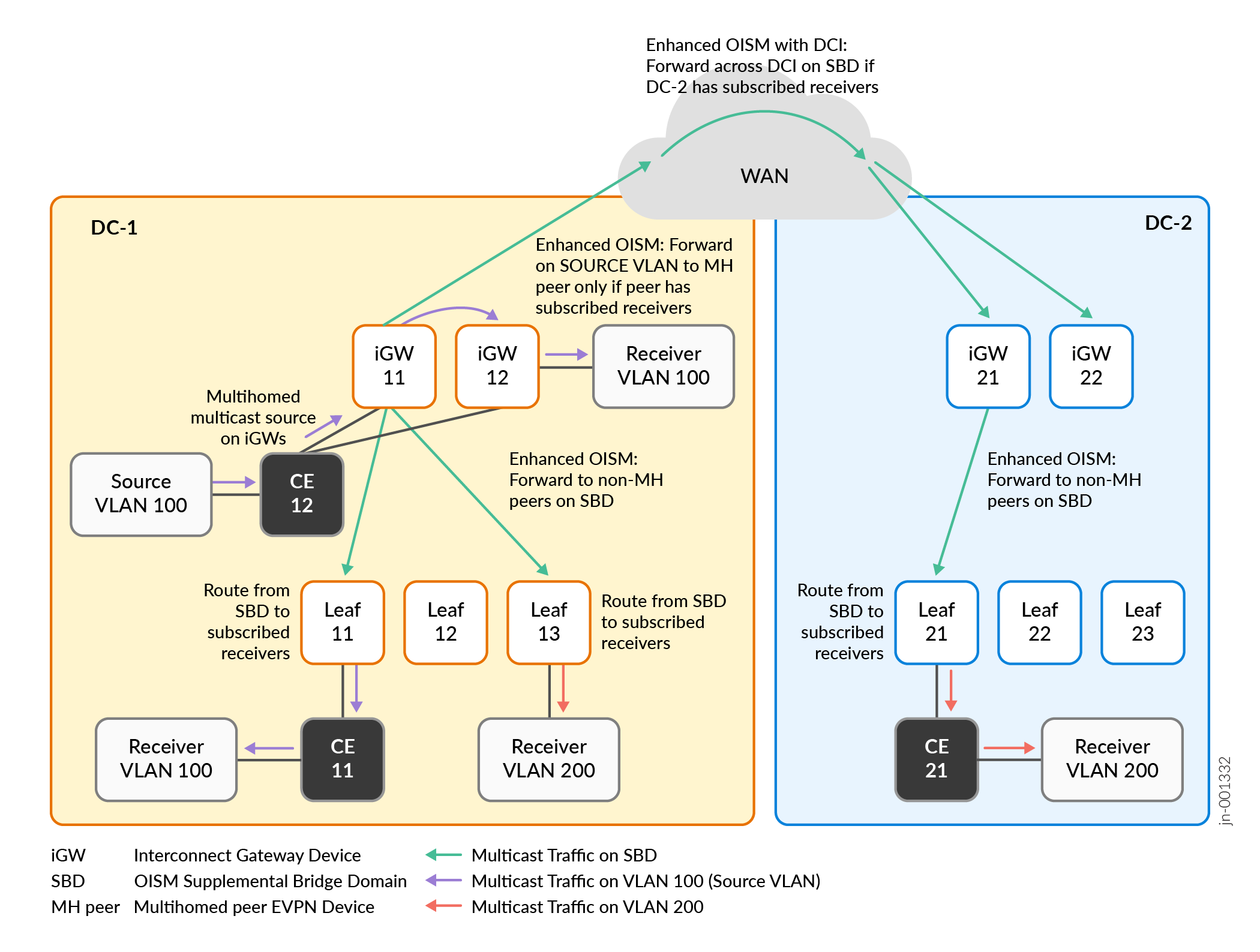
In this use case:
The multicast source is in DC-1 on VLAN 100, behind CE 12. CE 12 is multihomed to the two iGW devices in DC-1, iGW 11 and iGW 12.
Receivers in both DC-1 and DC-2 on VLAN 200 subscribe to the multicast data from the source in DC-1. Receivers in DC-1 on VLAN 100 behind iGW 12 and behind Leaf 11 also subscribe to the multicast data.
In DC-1, both iGW devices receive the multicast traffic from the source on VLAN 100. Both of the iGW devices in DC-1 know from receiving the SMET routes that there are receivers in DC-1 and remote receivers in DC-2. In this case, iGW 11 is the DF for the iGW devices in DC-1, so iGW 11:
Routes the traffic on the SBD across the DCI toward DC-2.
Forwards the traffic locally on the source VLAN to its multihoming peer, iGW 12.
Routes the traffic locally on the SBD to the other (non-multihoming peer) OISM leaf devices in DC-1.
In DC-1, the multihoming peer iGW device, iGW 12, forwards the traffic on the source VLAN to its local receiver. The other OISM leaf devices in DC-1 route the traffic from the SBD toward the receivers on the receiver VLANs (VLAN 100 and VLAN 200).
In DC-2, the iGW devices receive the multicast traffic on the SBD. In this case, iGW 21 is the DF for the iGW devices in DC-2, so iGW 21 forwards the traffic on the SBD to Leaf 21 toward the subscribed receiver.
In DC-2, Leaf 21 routes the multicast traffic toward the receiver on the receiver VLAN, VLAN 200.
See Multicast Next Hops Convergence Optimization for more on how we improve EVPN multicast next hop convergence over the DCI when DF and NDF status changes for the peer iGW devices in a data center.
Multicast Traffic Flow from External Source to Internal Receivers
Figure 5 shows a use case where the iGW devices in DC-1 also act as the OISM PEG devices to connect to a source in an external PIM domain.
The receivers in this use case are behind customer edge (CE) devices connected to the leaf devices inside each of the interconnected data centers.
For simplicity, we omit showing the receivers behind the CE devices here. The CE devices don't serve in an EVPN OISM leaf device role and you don't configure OISM on these devices.
For details on how OISM works with an external source and internal receivers, see Multicast Traffic from an External Source to Receivers Inside the EVPN Data Center—L3 Interface Method or Non-EVPN IRB Method.
You configure:
The iGW devices in DC-1 as OISM border leaf PEG devices.
The iGW devices in DC-2 as OISM server leaf devices.
The remaining leaf devices in both data centers as OISM server leaf devices.
We include a topology variation here with a receiver behind CE 12 in DC-1, where CE 12 is multihomed to OISM server leaf devices Leaf 12 and Leaf 13 for redundancy. These two leaf devices share an Ethernet segment identifier (ESI) for the multihomed receiver, and elect a DF for the ESI. In this case, Leaf 12 is the DF that forwards the multicast traffic destined for the receiver behind CE 12.

In this use case:
Receivers in DC-1 and DC-2 on VLAN 100 and VLAN 200 subscribe to the multicast data from the external source.
In DC-1, iGW 11 and iGW 12 receive the multicast traffic from the external source. Both of the iGWs in DC-1 know from receiving the SMET routes that there are receivers in DC-1 and remote receivers in DC-2. In this case, iGW 11 is the DF for the iGW devices in DC-1, so iGW 11:
Routes the traffic on the SBD across the DCI to the iGW devices in DC-2.
Routes the traffic locally on the SBD to the OISM leaf devices in DC-1 that are not its multihoming peers and have subscribed receivers—in this case, Leaf 11, Leaf 12 and Leaf 13.
In DC-1, the OISM leaf devices route the traffic from the SBD toward the receivers on the receiver VLANs—VLAN 100 and VLAN 200. In this case, a receiver is behind CE 12, which is multihomed to Leaf 12 and Leaf 13. Leaf 12 is the DF and forwards the multicast traffic toward that receiver.
In DC-2, the iGW devices receive the multicast traffic on the SBD. In this case, iGW 22 is the DF for the iGW devices in DC-2, so iGW 22 forwards the traffic on the SBD to Leaf 21 toward the subscribed receiver.
In DC-2, Leaf 21 routes the multicast traffic from the SBD toward the receiver on the receiver VLAN, VLAN 200.
Multicast Control and Data Flow for Internal Source to External Receiver
Figure 6 shows a use case where the source is in DC-1. We have a receiver across the DCI in DC-2 and an external receiver. The iGW devices in DC-1 are the OISM PEG devices connecting to the receiver in an external PIM domain.
For details on how OISM works with an internal source and external receiver, see Multicast Traffic from an Internal Source to Receivers Outside the EVPN Data Center—L3 Interface Method or Non-EVPN IRB Method.
For details on how enhanced OISM ensures that the OISM PEG devices correctly perform PIM source registration for multicast sources inside an EVPN data center to an external PIM domain, see PIM Registration with Enhanced OISM for Internal Sources Based on EVPN Type 10 S-PMSI A-D Routes.
The multicast source and iGW devices in the OISM border leaf PEG role are in the same data center in this use case. However, with an external receiver, the multicast source might not be in the same data center as the OISM PEG devices that connect to the external receivers. The seamless enhanced OISM multicast over DCI implementation ensures that multicast source traffic from any of the interconnected data centers can reach external receivers wherever the OISM border leaf PEG devices are. As a result, Figure 6 also shows the following control flow:
The OISM PEG devices advertise their PEG role in the local data center and across the DCI to the other iGW devices.
The OISM PEG devices send these advertisements on the OISM SBD in the SMET EVPN Type 6 routes, and in Inclusive Multicast Ethernet Tag (IMET) routes, which are EVPN Type 3 routes.
In this use case, you configure:
The iGW devices in DC-1 as OISM border leaf PEG devices.
The iGW devices in DC-2 as OISM server leaf devices.
The remaining EVPN PE leaf devices in both data centers as OISM server leaf devices.
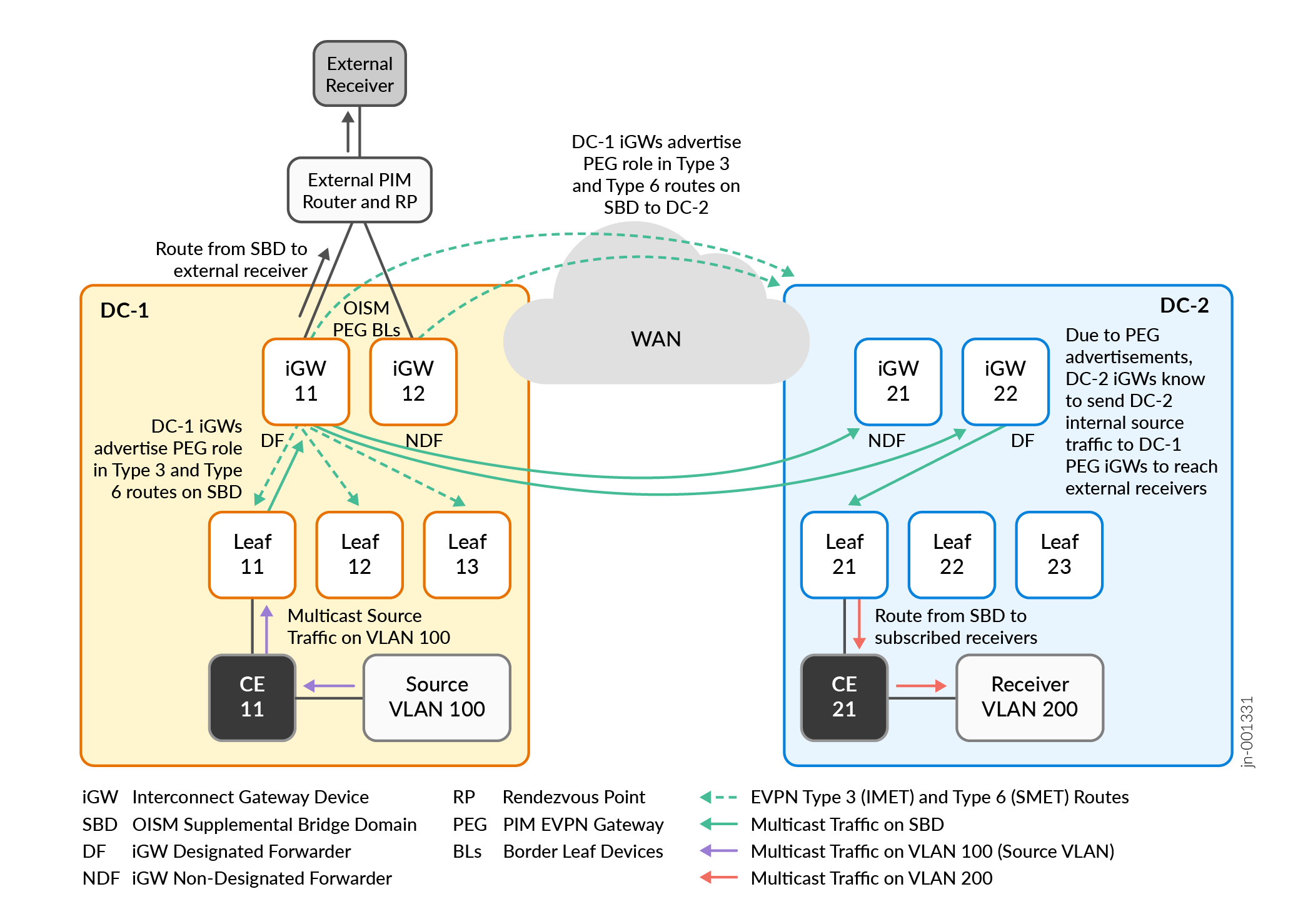
In this use case:
The iGW devices in DC-1 connected to the external PIM domain advertise that they are OISM PEG devices using EVPN Type 3 and Type 6 routes. The PEG devices send these advertisements to all local OISM PE devices in DC-1 and across the DCI to the iGW devices in DC-2.
A receiver in DC-2 on VLAN 200 and an external receiver subscribe to the multicast data from the source on VLAN 100 in DC-1.
In DC-1, Leaf 11 receives multicast traffic from the source on VLAN 100. Leaf 11 knows from receiving EVPN Type 6 SMET routes that DC-2 has a receiver and there is an external receiver connected by way of the iGW devices in OISM PEG role. As a result, Leaf 11 routes the multicast traffic to iGW 11 and iGW 12 on the SBD.
In DC-1, iGW 11 and iGW 12 receive the multicast traffic from Leaf 11 on the SBD. The iGW devices know from receiving EVPN Type 6 SMET routes that there are remote receivers in DC-2. The iGW devices also act as OISM border leaf PEG devices to the external receiver. In this case, Figure 6 shows that:
iGW 11 is the DF for the iGW devices in DC-1, so iGW 11 forwards the multicast traffic on the SBD across the DCI to the iGW devices in DC-2.
iGW 11 routes the multicast traffic toward the external receiver.
In DC-2, the iGW devices receive the multicast traffic on the SBD. In this case, iGW 22 is the DF for the iGW devices in DC-2, so iGW 22 forwards the traffic on the SBD to Leaf 21 toward the subscribed receiver.
In DC-2, Leaf 21 routes the multicast traffic from the SBD toward the receiver on the receiver VLAN, VLAN 200.
If DC-2 included a multicast data source, an external receiver connected to DC-1 might subscribe to that source data. In that case, the iGW devices in DC-2 receive the PEG role advertisements from the DC-1 iGW devices. The iGW devices in DC-2 would send multicast source traffic to an external receiver seamlessly using their interconnection to the DC-1 iGW devices acting as the OISM border leaf PEG devices.
Multicast Next Hops Convergence Optimization
When you interconnect EVPN data centers, we identify the peer multihomed iGW devices in each data center with a unique interconnect Ethernet segment ID (I-ESI). The peer iGW devices in each data center have a designated forwarder (DF) that forwards traffic across the interconnection and to the local receivers in the data center. The other iGW devices that are the NDF devices (sometimes called backup DF [BDF] devices) forward traffic only to receivers that are local to their own device.
The control plane on the iGW devices determines the multicast next hops for the DF and NDF iGW devices, and installs the next hops on the Packet Forwarding Engine (PFE) to efficiently forward traffic toward the destinations.
To improve multicast next hop information convergence in the PFE for EVPN multicast traffic over DCI, the iGW devices use a session model to track I-ESI DF and NDF status and multicast next hop information.
The control plane on the iGW devices:
Assigns a session ID to identify the DF and NDF device sessions.
Sends session status update messages to the PFE when the DF and NDF status for the I-ESI changes.
Upon receiving DF and NDF session status updates, the PFE on the iGW devices can quickly update the forwarding paths accordingly.
You can use the show multicast next-hops session command to see the DF and NDF session information for the I-ESI on iGW devices that you configure to support enhanced OISM traffic across the DCI.
Configure EVPN-VXLAN DCI with Enhanced OISM
To enable seamless multicast optimization with DCI and enhanced OISM, you configure many statements to set up EVPN-VXLAN, DCI, and enhanced OISM in each data center.
Keep in mind the following when planning an optimized DCI multicast environment:
We support enhanced OISM only in EVPN-VXLAN ERB overlay architectures.
If your environment includes external multicast sources or receivers, you configure EVPN devices in one of the data centers to act as the OISM border leaf PEG devices to connect to the external PIM domain. You can configure the iGW devices to also be the OISM PEG devices, or other OISM leaf devices in one of the data centers can be the OISM PEG devices.
This section provides a high-level overview of the different components you configure for multicast with enhanced OISM over DCI. We also include a simple sample configuration in Sample Configuration for DCI with Enhanced OISM, and corresponding verification show command outputs in Show Commands to Verify DCI with Enhanced OISM.
- Configure EVPN-VXLAN in Each Data Center
- Configure DCI Gateway Devices across Data Centers
- Configure Enhanced OISM in Each Data Center
Configure EVPN-VXLAN in Each Data Center
Configure the EVPN-VXLAN networks in the data centers on both sides of the interconnection. See Configure DCI Gateway Devices across Data Centers for more on how to set up the data centers for DCI.
We support DCI and enhanced OISM with interconnected EVPN-VXLAN data centers that use IPv4 underlay peering or IPv6 underlay peering. You can transfer IPv4 multicast data or IPv6 multicast data across DCI with either type of underlay.
See the following references for how to configure an IPv6 underlay with EVPN-VXLAN:
Configure DCI Gateway Devices across Data Centers
You configure the iGW devices to interconnect the data centers the same way you would without configuring enhanced OISM.
See the interconnect configuration hierarchy, and the following reference for a DCI stitching configuration example:
Configure Enhanced OISM in Each Data Center
Configure enhanced OISM in the EVPN-VXLAN data center on each side of the DCI in one of the many different use cases on this page with multicast source and multicast receiver locations. Optimized Intersubnet Multicast (OISM) in EVPN Networks has details on other supported OISM use cases in a data center.
Note the following about configuring enhanced OISM:
-
You enable enhanced OISM mode on all OISM devices using the
enhanced-oismoption at the[edit forwarding-options multicast-replication evpn irb]hierarchy level. You use theenhanced-oismoption instead of the regular OISM modeoismoption at the same hierarchy level. Theenhanced-oismandoismoptions are mutually exclusive. All EVPN PE devices in each data center must use enhanced OISM mode. -
With enhanced OISM, you can configure each OISM device with only the VLANs that device hosts. You don't need to configure all VLANs in the EVPN network on all OISM devices like you do with regular OISM. The exception is multihoming peer OISM devices—on those devices, you must configure the OISM revenue VLANs symmetrically on all peers. This requirement applies to the peer DCI gateways in each data center when you configure them as OISM server leaf devices or OISM border leaf devices.
-
You must configure the OISM SBD with the same VLAN ID in the matching tenant virtual routing and forwarding (VRF) instances in the interconnected data centers.
OISM requires some common configuration statements on both OISM server leaf devices and OISM border leaf devices. You configure some statements only on the server leaf devices, and configure some statements only on the border leaf devices. See Optimized Intersubnet Multicast (OISM) in EVPN Networks for details on understanding and configuring server leaf and border leaf OISM device roles and all elements for OISM to work (some options are platform-specific).
See the following sections in Optimized Intersubnet Multicast (OISM) in EVPN Networks for configuration considerations, steps to configure each OISM device role, and CLI commands to verify OISM operation:
Sample Configuration for DCI with Enhanced OISM
The following sections show a simple sample configuration for DCI with enhanced OISM with two stitched data centers, DC-1 and DC-2, similar to the topologies in the use cases in Figure 3 through Figure 6.
The setup uses the following parameters:
Interconnect WAN
OSPF underlay peering
IBGP overlay peering for EVPN
DCI EVPN instance: evpn-vxlan-A
EBGP underlay and overlay peering
DC-1 EVPN instance RT—target:9:9
DC-2 EVPN instance RT—target:21:21
WAN (interconnect) RT—target:11:11
L3 VRF instance: VRF-1 (RT target:1:2)
OISM SBD VLAN: VLAN_4
OISM tenant VLANs: VLAN_2, VLAN_3, VLAN_5
Note: Remember that with enhanced OISM, you must configure the same tenant VLANs on OISM multihoming peer PE devices. On all of the other OISM devices,you only need to configure the VLANs hosted by that device.Multicast groups (IPv4): 233.252.0.1, 233.252.0.2
Multicast source IP address: 172.20.1.15
External multicast PIM RP static address: (IPv4) 172.30.7.7, (IPv6) 2001:0db8::172:30:7:7
Device |
Device Address |
VRF-1 Router ID |
AS # |
EVPN Instance RD |
VRF-1 RD |
Interconnect RD |
Tenant VLANs |
|---|---|---|---|---|---|---|---|
WAN Router |
192.168.50.50 |
n/a |
65000 |
n/a |
n/a |
n/a |
n/a |
DC-1—AS 65111 ERB overlay with transit lean spine devices connecting the multihoming peer interconnect gateway devices iGW-11 and iGW-12 devices to eash other and to the other leaf devices:
Interconnect ESI for peer iGW devices iGW-11 and iGW-12—00:0a:0b:0c:0d:0a:0b:0c:0d:0a |
|||||||
iGW-11 |
192.168.1.1 |
192.168.1.2 |
65101 |
192.168.1.1:9 |
192.168.1.1:8 |
111:100 |
VLAN_2, VLAN_5 |
iGW-12 |
192.168.2.1 |
192.168.2.2 |
65102 |
192.168.1.1:9 |
192.168.2.1:8 |
112:100 |
VLAN_2, VLAN_5 |
Leaf-11 |
192.168.3.1 |
192.168.3.2 |
65103 |
192.168.3.1:9 |
192.168.3.1:8 |
n/a |
VLAN_2, VLAN_5 |
Leaf-12 |
192.168.4.1 |
192.168.4.2 |
65104 |
192.168.4.1:9 |
192.168.4.1:8 |
n/a |
VLAN_2, VLAN_5 |
Leaf-13 |
192.168.5.1 |
192.168.5.2 |
65105 |
192.168.5.1:9 |
192.168.5.1:8 |
n/a |
VLAN_3, VLAN_5 |
DC-2—AS 65222 In this ERB overlay data center, Leaf-21, Leaf-22, Leaf-23 are directly connected to the multihoming peer interconnect gateway devices iGW-21 and iGW-22, without a transit lean spine layer. Interconnect ESI for peer iGW devices iGW-21 and iGW-22—00:aa:bb:cc:dd:aa:bb:cc:dd:aa |
|||||||
iGW-21 |
192.168.21.1 |
192.168.21.2 |
65201 |
192.168.21.1:9 |
192.168.21.1:8 |
221:100 |
VLAN_3, VLAN_5 |
iGW-22 |
192.168.22.1 |
192.168.22.2 |
65202 |
192.168.22.1:9 |
192.168.22.1:8 |
222:100 |
VLAN_3, VLAN_5 |
Leaf-21 |
192.168.23.1 |
192.168.23.2 |
65203 |
192.168.23.1:9 |
192.168.23.1:8 |
n/a |
VLAN_2, VLAN_5 |
Leaf-22 |
192.168.24.1 |
192.168.24.2 |
65204 |
192.168.24.1:9 |
192.168.24.1:8 |
n/a |
VLAN_2, VLAN_5 |
Leaf-23 |
192.168.25.1 |
192.168.25.2 |
65205 |
192.168.25.1:9 |
192.168.25.1:8 |
n/a |
VLAN_3, VLAN_5 |
We provide sample configurations for DCI seamless stitching and enhanced OISM on the following devices in the topology:
WAN router: Simple EVPN overlay for seamless stitching across DC-1 and DC-2
DC-1: Multihoming interconnect peers iGW-11 and iGW-12, and Leaf-11
DC-2: iGW-21 and Leaf-21
The configuration on the multihoming interconnect peer iGW-22 in DC-2 would be similar to the configuration on iGW-21. The same applies to the configurations for Leaf-12, Leaf-13, Leaf-22, and Leaf-23.
- Related Platform-Specific Configuration Elements for EVPN-VXLAN Configurations
- WAN Router EVPN Overlay Sample Configuration
- DC-1: iGW-11 Sample Configuration
- DC-1: iGW-12 Sample Configuration
- DC-1: Leaf-11 Sample Configuration
- DC-2: iGW-21 Sample Configuration
- DC-2: Leaf-21 Sample Configuration
Related Platform-Specific Configuration Elements for EVPN-VXLAN Configurations
We require you to include the following statements in EVPN-VXLAN configurations with OISM or DCI on some platforms. Remember to add these statements to the indicated type of OISM device or DCI gateway device configuration on the stated platforms:
conserve-mcast-routes-in-pfeat the[edit routing-instances evpn-instance-name multicast-snooping-options oism]hierarchy level:Required on devices in the OISM server leaf or border leaf role on Junos OS Evolved QFX Series switches and ACX Series routers. For example, in our configuration:
set routing-instances evpn-vxlan-A multicast-snooping-options oism conserve-mcast-routes-in-pfe
vxlan-dci-enableat the[edit <routing-instances instance-name> forwarding-options]hierarchy level:Required only on EX4400 switches you configure as DCI gateway devices for DCI stitching to work (with or without enhanced OISM). For example:
set forwarding-options vxlan-dci-enable
For details, see evpn-vxlan.
shared-tunnelsat the[edit forwarding-options evpn-vxlan]hierarchy level:Required for any EVPN devices that are Junos OS EX Series or QFX Series switches. For example:
set forwarding-options evpn-vxlan shared-tunnels
For details, see evpn-vxlan and Shared VTEP Tunnels in EVPN-VXLAN Fabrics with Multiple MAC-VRF Routing Instances.
WAN Router EVPN Overlay Sample Configuration
set chassis aggregated-devices ethernet device-count 10
set interfaces mge-0/0/12 description "CONNECTED TO iGW-11"
set interfaces mge-0/0/12 unit 0 family inet address 10.1.51.2/24
set interfaces mge-0/0/9 description "CONNECTED TO iGW-12"
set interfaces mge-0/0/9 unit 0 family inet address 10.2.52.2/24
set interfaces mge-0/0/10 description "CONNECTED TO iGW-21"
set interfaces mge-0/0/10 unit 0 family inet address 10.21.53.2/24
set interfaces mge-0/0/11 description "CONNECTED TO iGW-22"
set interfaces mge-0/0/11 unit 0 family inet address 10.22.54.2/24
set interfaces lo0 unit 0 family inet address 192.168.50.50/32

set routing-options router-id 192.168.50.50
set routing-options autonomous-system 65000

set protocols bgp group OVERLAY-WAN type internal
set protocols bgp group OVERLAY-WAN family evpn signaling
set protocols bgp group OVERLAY-WAN cluster 192.168.50.50
set protocols bgp group OVERLAY-WAN local-as 65000
set protocols bgp group OVERLAY-WAN neighbor 192.168.1.1
set protocols bgp group OVERLAY-WAN neighbor 192.168.2.1
set protocols bgp group OVERLAY-WAN neighbor 192.168.21.1
set protocols bgp group OVERLAY-WAN neighbor 192.168.22.1
set protocols ospf traffic-engineering
set protocols ospf area 0.0.0.0 interface mge-0/0/9.0
set protocols ospf area 0.0.0.0 interface mge-0/0/10.0
set protocols ospf area 0.0.0.0 interface mge-0/0/11.0
set protocols ospf area 0.0.0.0 interface mge-0/0/12.0
set protocols ospf area 0.0.0.0 interface lo0.0

set protocols lldp port-id-subtype interface-name
set protocols lldp tlv-select system-name
set protocols lldp interface all
DC-1: iGW-11 Sample Configuration
set system host-name iGW-11
set routing-options router-id 192.168.1.1
set routing-options autonomous-system 65111

#Interfaces configuration

set chassis aggregated-devices ethernet device-count 10
set chassis network-services enhanced-ip
set protocols lldp port-id-subtype interface-name
set protocols lldp tlv-select system-name
set protocols lldp tlv-select system-capabilities
set protocols lldp interface all

set interfaces et-0/0/0 number-of-sub-ports 4
set interfaces et-0/0/0 speed 10g

set interfaces et-0/0/0:0 description "CONNECTED TO CE-Host"
set interfaces et-0/0/0:0 unit 0 family ethernet-switching interface-mode trunk
set interfaces et-0/0/0:0 unit 0 family ethernet-switching vlan members VLAN_2
set interfaces et-0/0/0:0 unit 0 family ethernet-switching vlan members VLAN_5

set interfaces et-0/0/0:1 description "CONNECTED TO CE-Host"
set interfaces et-0/0/0:1 ether-options 802.3ad ae0
set interfaces ae0 description "CONNECTED TO CE-Host"
set interfaces ae0 esi 00:44:44:44:44:44:44:44:44:44
set interfaces ae0 esi all-active
set interfaces ae0 aggregated-ether-options minimum-links 1
set interfaces ae0 aggregated-ether-options lacp active
set interfaces ae0 aggregated-ether-options lacp periodic fast
set interfaces ae0 aggregated-ether-options lacp system-id 00:44:44:44:44:44
set interfaces ae0 unit 0 family ethernet-switching interface-mode trunk
set interfaces ae0 unit 0 family ethernet-switching vlan members VLAN_2
set interfaces ae0 unit 0 family ethernet-switching vlan members VLAN_5

set interfaces et-0/0/0:2 description "CONNECTED TO PIM RP"
set interfaces et-0/0/0:2 unit 0 family inet address 172.30.80.1/24
set interfaces et-0/0/0:2 unit 0 family inet6 address 2001:0db8:80::1/64

set interfaces et-0/0/1 number-of-sub-ports 4
set interfaces et-0/0/1 speed 10g
set interfaces et-0/0/1:0 description "CONNECTED TO SPINE-1"
set interfaces et-0/0/1:0 ether-options 802.3ad ae1
set interfaces ae1 aggregated-ether-options lacp active
set interfaces ae1 aggregated-ether-options lacp periodic fast
set interfaces ae1 unit 0 family inet address 10.1.7.2/24
set interfaces et-0/0/1:1 description "CONNECTED TO SPINE-2"
set interfaces et-0/0/1:1 unit 0 family inet address 10.1.8.2/24
set interfaces et-0/0/1:2 description "CONNECTED TO WAN Router"
set interfaces et-0/0/1:2 unit 0 family inet address 10.1.51.1/24

# EBGP underlay and overlay peering for EVPN

set policy-options policy-statement EXPORT-LO0 term LOOPBACK from protocol direct
set policy-options policy-statement EXPORT-LO0 term LOOPBACK from interface lo0.0
set policy-options policy-statement EXPORT-LO0 term LOOPBACK then accept
set policy-options policy-statement EXPORT-LO0 term REJECT then reject
set policy-options policy-statement load-balancing-policy then load-balance per-packet
set routing-options forwarding-table export load-balancing-policy

set protocols bgp group IP-UNDERLAY type external
set protocols bgp group IP-UNDERLAY export EXPORT-LO0
set protocols bgp group IP-UNDERLAY local-as 10001
set protocols bgp group IP-UNDERLAY multipath multiple-as
set protocols bgp group IP-UNDERLAY bfd-liveness-detection minimum-interval 350
set protocols bgp group IP-UNDERLAY bfd-liveness-detection multiplier 3
set protocols bgp group IP-UNDERLAY bfd-liveness-detection session-mode automatic
set protocols bgp group IP-UNDERLAY neighbor 10.1.7.1 peer-as 65107
set protocols bgp group IP-UNDERLAY neighbor 10.1.8.1 peer-as 65108
set protocols bgp group IP-OVERLAY type external
set protocols bgp group IP-OVERLAY multihop ttl 2
set protocols bgp group IP-OVERLAY multihop no-nexthop-change
set protocols bgp group IP-OVERLAY local-address 192.168.1.1
set protocols bgp group IP-OVERLAY family inet-vpn unicast
set protocols bgp group IP-OVERLAY family evpn signaling
set protocols bgp group IP-OVERLAY local-as 65101
set protocols bgp group IP-OVERLAY bfd-liveness-detection minimum-interval 350
set protocols bgp group IP-OVERLAY bfd-liveness-detection multiplier 3
set protocols bgp group IP-OVERLAY bfd-liveness-detection session-mode automatic
set protocols bgp group IP-OVERLAY neighbor 192.168.4.1 peer-as 65104
set protocols bgp group IP-OVERLAY neighbor 192.168.5.1 peer-as 65105
set protocols bgp group IP-OVERLAY neighbor 192.168.2.1 peer-as 65102
set protocols bgp group IP-OVERLAY neighbor 192.168.3.1 peer-as 65103

# WAN overlay

set protocols bgp group OVERLAY-WAN type internal
set protocols bgp group OVERLAY-WAN local-address 192.168.1.1
set protocols bgp group OVERLAY-WAN family evpn signaling
set protocols bgp group OVERLAY-WAN local-as 65000
set protocols bgp group OVERLAY-WAN neighbor 192.168.50.50

# EVPN instance with enhanced OISM - enable snooping and SMET, define tenant VLANs and OISM SBD

set interfaces irb mtu 1514
set interfaces irb unit 2 virtual-gateway-accept-data
set interfaces irb unit 2 family inet address 10.102.1.1/24 virtual-gateway-address 10.102.1.100
set interfaces irb unit 2 family inet6 address 2001:0db8:10:102::1/64 virtual-gateway-address 2001:0db8:10:102::100
set interfaces irb unit 2 mac 00:01:00:01:00:01
set interfaces irb unit 4 virtual-gateway-accept-data
set interfaces irb unit 4 family inet address 10.104.1.1/24 virtual-gateway-address 10.104.1.100
set interfaces irb unit 4 family inet6 address 2001:0db8:10:104::1/64 virtual-gateway-address 2001:0db8:10:104::100
set interfaces irb unit 4 mac 00:01:00:03:00:01
set interfaces irb unit 5 virtual-gateway-accept-data
set interfaces irb unit 5 family inet address 10.105.1.1/24 virtual-gateway-address 10.105.1.100
set interfaces irb unit 5 family inet6 address 2001:0db8:10:105::1/64 virtual-gateway-address 2001:0db8:10:105::100
set interfaces irb unit 5 mac 00:01:00:04:00:01
set interfaces lo0 unit 0 family inet address 192.168.1.1/32 primary
set interfaces lo0 unit 1 family inet address 192.168.1.2/32
set interfaces lo0 unit 1 family inet6 address 2001:0db8::192:168:1:2/128

set forwarding-options multicast-replication evpn irb enhanced-oism

set routing-instances evpn-vxlan-A instance-type mac-vrf
set routing-instances evpn-vxlan-A protocols igmp-snooping vlan VLAN_2 proxy
set routing-instances evpn-vxlan-A protocols igmp-snooping vlan VLAN_4 proxy
set routing-instances evpn-vxlan-A protocols igmp-snooping vlan VLAN_5 proxy
set routing-instances evpn-vxlan-A protocols mld-snooping vlan VLAN_2
set routing-instances evpn-vxlan-A protocols mld-snooping vlan VLAN_4
set routing-instances evpn-vxlan-A protocols mld-snooping vlan VLAN_5
set routing-instances evpn-vxlan-A protocols evpn encapsulation vxlan
set routing-instances evpn-vxlan-A protocols evpn default-gateway no-gateway-community
set routing-instances evpn-vxlan-A protocols evpn extended-vni-list 2
set routing-instances evpn-vxlan-A protocols evpn extended-vni-list 4
set routing-instances evpn-vxlan-A protocols evpn extended-vni-list 5
set routing-instances evpn-vxlan-A vtep-source-interface lo0.0
set routing-instances evpn-vxlan-A service-type vlan-aware
set routing-instances evpn-vxlan-A interface et-0/0/0:0.0
set routing-instances evpn-vxlan-A interface ae0.0
set routing-instances evpn-vxlan-A route-distinguisher 192.168.1.1:9
set routing-instances evpn-vxlan-A vrf-target target:9:9

set routing-instances evpn-vxlan-A vlans VLAN_2 vlan-id 2
set routing-instances evpn-vxlan-A vlans VLAN_2 l3-interface irb.2
set routing-instances evpn-vxlan-A vlans VLAN_2 vxlan vni 2
set routing-instances evpn-vxlan-A vlans VLAN_4 vlan-id 4
set routing-instances evpn-vxlan-A vlans VLAN_4 l3-interface irb.4
set routing-instances evpn-vxlan-A vlans VLAN_4 vxlan vni 4
set routing-instances evpn-vxlan-A vlans VLAN_5 vlan-id 5
set routing-instances evpn-vxlan-A vlans VLAN_5 l3-interface irb.5
set routing-instances evpn-vxlan-A vlans VLAN_5 vxlan vni 5

# DCI parameters and multihoming peer designation

set routing-instances evpn-vxlan-A protocols evpn interconnect vrf-target target:11:11
set routing-instances evpn-vxlan-A protocols evpn interconnect route-distinguisher 111:100
set routing-instances evpn-vxlan-A protocols evpn interconnect esi 00:0a:0b:0c:0d:0a:0b:0c:0d:0a
set routing-instances evpn-vxlan-A protocols evpn interconnect esi all-active
set routing-instances evpn-vxlan-A protocols evpn interconnect esi df-election-type preference value 300
set routing-instances evpn-vxlan-A protocols evpn interconnect interconnected-vni-list all

set protocols evpn interconnect-multihoming-peer-gateways 192.168.2.1

set protocols ospf area 0.0.0.0 interface lo0.0
set protocols ospf area 0.0.0.0 interface et-0/0/1:2.0

# Tenant VRF VRF-1 configuration, including OISM PEG setting and external multicast routing parameters

set routing-instances VRF-1 instance-type vrf
set routing-instances VRF-1 routing-options router-id 192.168.1.2
set routing-instances VRF-1 protocols evpn oism supplemental-bridge-domain-irb irb.4
set routing-instances VRF-1 protocols evpn oism pim-evpn-gateway
set routing-instances VRF-1 protocols ospf area 0.0.0.0 interface lo0.1
set routing-instances VRF-1 protocols ospf area 0.0.0.0 interface irb.4
set routing-instances VRF-1 protocols ospf area 0.0.0.0 interface irb.2 passive
set routing-instances VRF-1 protocols ospf area 0.0.0.0 interface irb.5 passive
set routing-instances VRF-1 protocols ospf area 0.0.0.0 interface et-0/0/0:2.0
set routing-instances VRF-1 protocols ospf3 area 0.0.0.0 interface lo0.1
set routing-instances VRF-1 protocols ospf3 area 0.0.0.0 interface irb.4
set routing-instances VRF-1 protocols ospf3 area 0.0.0.0 interface irb.2 passive
set routing-instances VRF-1 protocols ospf3 area 0.0.0.0 interface irb.5 passive
set routing-instances VRF-1 protocols ospf3 area 0.0.0.0 interface et-0/0/0:2.0
set routing-instances VRF-1 protocols pim rp static address 172.30.7.7
set routing-instances VRF-1 protocols pim rp static address 2001:0db8::172:30:7:7
set routing-instances VRF-1 protocols pim interface et-0/0/0:2.0
set routing-instances VRF-1 protocols pim interface irb.2 distributed-dr
set routing-instances VRF-1 protocols pim interface irb.4 accept-remote-source
set routing-instances VRF-1 protocols pim interface irb.5 distributed-dr
set routing-instances VRF-1 protocols pim interface lo0.1
set routing-instances VRF-1 protocols pim disable-packet-register
set routing-instances VRF-1 interface et-0/0/0:2.0
set routing-instances VRF-1 interface irb.2
set routing-instances VRF-1 interface irb.4
set routing-instances VRF-1 interface irb.5
set routing-instances VRF-1 interface lo0.1
set routing-instances VRF-1 route-distinguisher 192.168.1.1:8
set routing-instances VRF-1 vrf-target target:1:2
set routing-instances VRF-1 vrf-table-label
DC-1: iGW-12 Sample Configuration
set system host-name iGW-12
set routing-options router-id 192.168.2.1
set routing-options autonomous-system 65111

# Interfaces configuration

set chassis aggregated-devices ethernet device-count 10
set chassis network-services enhanced-ip
set protocols lldp port-id-subtype interface-name
set protocols lldp tlv-select system-name
set protocols lldp tlv-select system-capabilities
set protocols lldp interface all

set interfaces et-0/0/0 number-of-sub-ports 4
set interfaces et-0/0/0 speed 10g

set interfaces et-0/0/0:0 description "CONNECTED TO CE-Host"
set interfaces et-0/0/0:0 unit 0 family ethernet-switching interface-mode trunk
set interfaces et-0/0/0:0 unit 0 family ethernet-switching vlan members VLAN_2
set interfaces et-0/0/0:0 unit 0 family ethernet-switching vlan members VLAN_5

set interfaces et-0/0/0:1 description "CONNECTED TO CE-Host"
set interfaces et-0/0/0:1 ether-options 802.3ad ae0
set interfaces ae0 description "CONNECTED TO CE-Host"
set interfaces ae0 esi 00:44:44:44:44:44:44:44:44:44
set interfaces ae0 esi all-active
set interfaces ae0 aggregated-ether-options minimum-links 1
set interfaces ae0 aggregated-ether-options lacp active
set interfaces ae0 aggregated-ether-options lacp periodic fast
set interfaces ae0 aggregated-ether-options lacp system-id 00:44:44:44:44:44
set interfaces ae0 unit 0 family ethernet-switching interface-mode trunk
set interfaces ae0 unit 0 family ethernet-switching vlan members VLAN_2
set interfaces ae0 unit 0 family ethernet-switching vlan members VLAN_5

set interfaces et-0/0/0:2 description "CONNECTED TO PIM RP"
set interfaces et-0/0/0:2 unit 0 family inet address 172.30.90.1/24
set interfaces et-0/0/0:2 unit 0 family inet6 address 2001:0db8:90::1/64

set interfaces et-0/0/1 number-of-sub-ports 4
set interfaces et-0/0/1 speed 10g
set interfaces et-0/0/1:0 description "CONNECTED TO SPINE-1"
set interfaces et-0/0/1:0 unit 0 family inet address 10.2.7.2/24
set interfaces et-0/0/1:1 description "CONNECTED TO SPINE-2"
set interfaces et-0/0/1:1 unit 0 family inet address 10.2.8.2/24
set interfaces et-0/0/1:2 description "CONNECTED TO WAN Router"
set interfaces et-0/0/1:2 unit 0 family inet address 10.2.52.1/24

# EBGP underlay and overlay peering for EVPN

set policy-options policy-statement EXPORT-LO0 term LOOPBACK from protocol direct
set policy-options policy-statement EXPORT-LO0 term LOOPBACK from interface lo0.0
set policy-options policy-statement EXPORT-LO0 term LOOPBACK then accept
set policy-options policy-statement EXPORT-LO0 term REJECT then reject
set policy-options policy-statement load-balancing-policy then load-balance per-packet
set routing-options forwarding-table export load-balancing-policy

set protocols bgp group IP-UNDERLAY type external
set protocols bgp group IP-UNDERLAY export EXPORT-LO0
set protocols bgp group IP-UNDERLAY local-as 65102
set protocols bgp group IP-UNDERLAY multipath multiple-as
set protocols bgp group IP-UNDERLAY bfd-liveness-detection minimum-interval 350
set protocols bgp group IP-UNDERLAY bfd-liveness-detection multiplier 3
set protocols bgp group IP-UNDERLAY bfd-liveness-detection session-mode automatic
set protocols bgp group IP-UNDERLAY neighbor 10.2.7.1 peer-as 65107
set protocols bgp group IP-UNDERLAY neighbor 10.2.8.1 peer-as 65108
set protocols bgp group IP-OVERLAY type external
set protocols bgp group IP-OVERLAY multihop ttl 2
set protocols bgp group IP-OVERLAY multihop no-nexthop-change
set protocols bgp group IP-OVERLAY local-address 192.168.2.1
set protocols bgp group IP-OVERLAY family inet-vpn unicast
set protocols bgp group IP-OVERLAY family evpn signaling
set protocols bgp group IP-OVERLAY local-as 65102
set protocols bgp group IP-OVERLAY bfd-liveness-detection minimum-interval 350
set protocols bgp group IP-OVERLAY bfd-liveness-detection multiplier 3
set protocols bgp group IP-OVERLAY bfd-liveness-detection session-mode automatic
set protocols bgp group IP-OVERLAY neighbor 192.168.3.1 peer-as 65103
set protocols bgp group IP-OVERLAY neighbor 192.168.5.1 peer-as 65105
set protocols bgp group IP-OVERLAY neighbor 192.168.1.1 peer-as 65101
set protocols bgp group IP-OVERLAY neighbor 192.168.4.1 peer-as 65104

# WAN overlay

set protocols bgp group OVERLAY-WAN type internal
set protocols bgp group OVERLAY-WAN local-address 192.168.2.1
set protocols bgp group OVERLAY-WAN family evpn signaling
set protocols bgp group OVERLAY-WAN local-as 65000
set protocols bgp group OVERLAY-WAN neighbor 192.168.50.50

# EVPN instance with enhanced OISM - enable snooping and SMET, define tenant VLANs and OISM SBD, and their IRB interfaces

set interfaces irb mtu 1514
set interfaces irb unit 2 virtual-gateway-accept-data
set interfaces irb unit 2 family inet address 10.102.1.2/24 virtual-gateway-address 10.102.1.100
set interfaces irb unit 2 family inet6 address 2001:0db8:10:102::2/64 virtual-gateway-address 2001:0db8:10:102::100
set interfaces irb unit 2 mac 00:01:00:01:00:02
set interfaces irb unit 4 virtual-gateway-accept-data
set interfaces irb unit 4 family inet address 10.104.1.2/24 virtual-gateway-address 10.104.1.100
set interfaces irb unit 4 family inet6 address 2001:0db8:10:104::2/64 virtual-gateway-address 2001:0db8:10:104::100
set interfaces irb unit 4 mac 00:01:00:03:00:02
set interfaces irb unit 5 virtual-gateway-accept-data
set interfaces irb unit 5 family inet address 10.105.1.2/24 virtual-gateway-address 10.105.1.100
set interfaces irb unit 5 family inet6 address 2001:0db8:10:105::2/64 virtual-gateway-address 2001:0db8:10:105::100
set interfaces irb unit 5 mac 00:01:00:04:00:02
set interfaces lo0 unit 0 family inet address 192.168.2.1/32 primary
set interfaces lo0 unit 1 family inet address 192.168.2.2/32
set interfaces lo0 unit 1 family inet6 address 2001:0db8::192:168:2:2/128

set forwarding-options multicast-replication evpn irb enhanced-oism

set routing-instances evpn-vxlan-A instance-type mac-vrf
set routing-instances evpn-vxlan-A protocols igmp-snooping vlan VLAN_2 proxy
set routing-instances evpn-vxlan-A protocols igmp-snooping vlan VLAN_4 proxy
set routing-instances evpn-vxlan-A protocols igmp-snooping vlan VLAN_5 proxy
set routing-instances evpn-vxlan-A protocols mld-snooping vlan VLAN_2
set routing-instances evpn-vxlan-A protocols mld-snooping vlan VLAN_4
set routing-instances evpn-vxlan-A protocols mld-snooping vlan VLAN_5
set routing-instances evpn-vxlan-A protocols evpn encapsulation vxlan
set routing-instances evpn-vxlan-A protocols evpn default-gateway no-gateway-community
set routing-instances evpn-vxlan-A protocols evpn extended-vni-list 2
set routing-instances evpn-vxlan-A protocols evpn extended-vni-list 4
set routing-instances evpn-vxlan-A protocols evpn extended-vni-list 5
set routing-instances evpn-vxlan-A vtep-source-interface lo0.0
set routing-instances evpn-vxlan-A service-type vlan-aware
set routing-instances evpn-vxlan-A interface et-0/0/0:0.0
set routing-instances evpn-vxlan-A interface ae0.0
set routing-instances evpn-vxlan-A route-distinguisher 192.168.2.1:9
set routing-instances evpn-vxlan-A vrf-target target:9:9

set routing-instances evpn-vxlan-A vlans VLAN_2 vlan-id 2
set routing-instances evpn-vxlan-A vlans VLAN_2 l3-interface irb.2
set routing-instances evpn-vxlan-A vlans VLAN_2 vxlan vni 2
set routing-instances evpn-vxlan-A vlans VLAN_4 vlan-id 4
set routing-instances evpn-vxlan-A vlans VLAN_4 l3-interface irb.4
set routing-instances evpn-vxlan-A vlans VLAN_4 vxlan vni 4
set routing-instances evpn-vxlan-A vlans VLAN_5 vlan-id 5
set routing-instances evpn-vxlan-A vlans VLAN_5 l3-interface irb.5
set routing-instances evpn-vxlan-A vlans VLAN_5 vxlan vni 5

# DCI parameters and multihoming peer designation

set routing-instances evpn-vxlan-A protocols evpn interconnect vrf-target target:11:11
set routing-instances evpn-vxlan-A protocols evpn interconnect route-distinguisher 112:100
set routing-instances evpn-vxlan-A protocols evpn interconnect esi 00:0a:0b:0c:0d:0a:0b:0c:0d:0a
set routing-instances evpn-vxlan-A protocols evpn interconnect esi all-active
set routing-instances evpn-vxlan-A protocols evpn interconnect esi df-election-type preference value 100
set routing-instances evpn-vxlan-A protocols evpn interconnect interconnected-vni-list all

set protocols evpn interconnect-multihoming-peer-gateways 192.168.1.1

set protocols ospf area 0.0.0.0 interface et-0/0/1:2.0
set protocols ospf area 0.0.0.0 interface lo0.0

# Tenant VRF VRF-1 configuration, including OISM PEG setting and external multicast routing parameters

set routing-instances VRF-1 instance-type vrf
set routing-instances VRF-1 routing-options router-id 192.168.2.2
set routing-instances VRF-1 protocols evpn oism supplemental-bridge-domain-irb irb.4
set routing-instances VRF-1 protocols evpn oism pim-evpn-gateway
set routing-instances VRF-1 protocols ospf area 0.0.0.0 interface lo0.1
set routing-instances VRF-1 protocols ospf area 0.0.0.0 interface irb.4
set routing-instances VRF-1 protocols ospf area 0.0.0.0 interface irb.2 passive
set routing-instances VRF-1 protocols ospf area 0.0.0.0 interface irb.5 passive
set routing-instances VRF-1 protocols ospf area 0.0.0.0 interface et-0/0/0:2.0
set routing-instances VRF-1 protocols ospf3 area 0.0.0.0 interface lo0.1
set routing-instances VRF-1 protocols ospf3 area 0.0.0.0 interface irb.4
set routing-instances VRF-1 protocols ospf3 area 0.0.0.0 interface irb.2 passive
set routing-instances VRF-1 protocols ospf3 area 0.0.0.0 interface irb.5 passive
set routing-instances VRF-1 protocols ospf3 area 0.0.0.0 interface et-0/0/0:2.0
set routing-instances VRF-1 protocols pim rp static address 172.30.7.7
set routing-instances VRF-1 protocols pim rp static address 2001:0db8::172:30:7:7
set routing-instances VRF-1 protocols pim interface irb.2 distributed-dr
set routing-instances VRF-1 protocols pim interface irb.4 accept-remote-source
set routing-instances VRF-1 protocols pim interface irb.5 distributed-dr
set routing-instances VRF-1 protocols pim interface lo0.1
set routing-instances VRF-1 protocols pim interface et-0/0/0:2.0
set routing-instances VRF-1 protocols pim disable-packet-register
set routing-instances VRF-1 interface et-0/0/0:2.0
set routing-instances VRF-1 interface irb.2
set routing-instances VRF-1 interface irb.4
set routing-instances VRF-1 interface irb.5
set routing-instances VRF-1 interface lo0.1
set routing-instances VRF-1 route-distinguisher 192.168.2.1:8
set routing-instances VRF-1 vrf-target target:1:2
set routing-instances VRF-1 vrf-table-label
DC-1: Leaf-11 Sample Configuration
set system host-name Leaf-11
set routing-options router-id 192.168.3.1
set routing-options autonomous-system 65111

# Interfaces configuration

set chassis aggregated-devices ethernet device-count 10
set chassis fpc 0 pic 0 port 0 channel-speed 10g
set chassis fpc 0 pic 0 port 1 channel-speed 10g
set chassis network-services enhanced-ip
set protocols lldp port-id-subtype interface-name
set protocols lldp tlv-select system-name
set protocols lldp tlv-select system-capabilities
set protocols lldp interface all

set interfaces xe-0/0/0:0 description "CONNECTED TO CE-Host"
set interfaces xe-0/0/0:0 unit 0 family ethernet-switching interface-mode trunk
set interfaces xe-0/0/0:0 unit 0 family ethernet-switching vlan members VLAN_2
set interfaces xe-0/0/0:0 unit 0 family ethernet-switching vlan members VLAN_5

set interfaces xe-0/0/0:1 description "CONNECTED TO CE-Host"
set interfaces xe-0/0/0:1 ether-options 802.3ad ae0
set interfaces ae0 description "CONNECTED TO CE-Host"
set interfaces ae0 esi 00:11:11:11:11:11:11:11:11:11
set interfaces ae0 esi all-active
set interfaces ae0 esi df-election-type preference value 100
set interfaces ae0 aggregated-ether-options lacp active
set interfaces ae0 aggregated-ether-options lacp periodic fast
set interfaces ae0 aggregated-ether-options lacp system-id 00:11:11:11:11:11
set interfaces ae0 unit 0 family ethernet-switching interface-mode trunk
set interfaces ae0 unit 0 family ethernet-switching vlan members VLAN_2
set interfaces ae0 unit 0 family ethernet-switching vlan members VLAN_5

set interfaces xe-0/0/1:0 description "CONNECTED TO SPINE-1"
set interfaces xe-0/0/1:0 unit 0 family inet address 10.3.7.2/24
set interfaces xe-0/0/1:1 description "CONNECTED TO SPINE-2"
set interfaces xe-0/0/1:1 unit 0 family inet address 10.3.8.2/24


# EBGP underlay and overlay peering for EVPN

set policy-options policy-statement EXPORT-LO0 term LOOPBACK from protocol direct
set policy-options policy-statement EXPORT-LO0 term LOOPBACK from interface lo0.0
set policy-options policy-statement EXPORT-LO0 term LOOPBACK then accept
set policy-options policy-statement EXPORT-LO0 term REJECT then reject
set policy-options policy-statement load-balancing-policy then load-balance per-packet
set routing-options forwarding-table export load-balancing-policy

set protocols bgp group IP-UNDERLAY type external
set protocols bgp group IP-UNDERLAY export EXPORT-LO0
set protocols bgp group IP-UNDERLAY local-as 65103
set protocols bgp group IP-UNDERLAY multipath multiple-as
set protocols bgp group IP-UNDERLAY bfd-liveness-detection minimum-interval 350
set protocols bgp group IP-UNDERLAY bfd-liveness-detection multiplier 3
set protocols bgp group IP-UNDERLAY bfd-liveness-detection session-mode automatic
set protocols bgp group IP-UNDERLAY neighbor 10.3.7.1 peer-as 65107
set protocols bgp group IP-UNDERLAY neighbor 10.3.8.1 peer-as 65108
set protocols bgp group IP-OVERLAY type external
set protocols bgp group IP-OVERLAY multihop ttl 2
set protocols bgp group IP-OVERLAY multihop no-nexthop-change
set protocols bgp group IP-OVERLAY local-address 192.168.3.1
set protocols bgp group IP-OVERLAY family inet-vpn unicast
set protocols bgp group IP-OVERLAY family evpn signaling
set protocols bgp group IP-OVERLAY local-as 65103
set protocols bgp group IP-OVERLAY bfd-liveness-detection minimum-interval 350
set protocols bgp group IP-OVERLAY bfd-liveness-detection multiplier 3
set protocols bgp group IP-OVERLAY bfd-liveness-detection session-mode automatic
set protocols bgp group IP-OVERLAY neighbor 192.168.1.1 peer-as 65101
set protocols bgp group IP-OVERLAY neighbor 192.168.4.1 peer-as 65104
set protocols bgp group IP-OVERLAY neighbor 192.168.5.1 peer-as 65105
set protocols bgp group IP-OVERLAY neighbor 192.168.2.1 peer-as 65102

# EVPN instance with enhanced OISM - enable snooping and SMET, define tenant VLANs and OISM SBD, and their IRB interfaces

set interfaces irb mtu 1500
set interfaces irb unit 2 virtual-gateway-accept-data
set interfaces irb unit 2 family inet address 10.102.1.3/24 virtual-gateway-address 10.102.1.100
set interfaces irb unit 2 family inet6 address 2001:0db8:10:102::3/64 virtual-gateway-address 2001:0db8:10:102::100
set interfaces irb unit 2 mac 00:01:00:01:00:04
set interfaces irb unit 4 virtual-gateway-accept-data
set interfaces irb unit 4 family inet address 10.104.1.3/24 virtual-gateway-address 10.104.1.100
set interfaces irb unit 4 family inet6 address 2001:0db8:10:104::3/64 virtual-gateway-address 2001:0db8:10:104::100
set interfaces irb unit 4 mac 00:01:00:03:00:04
set interfaces irb unit 5 virtual-gateway-accept-data
set interfaces irb unit 5 family inet address 10.105.1.3/24 virtual-gateway-address 10.105.1.100
set interfaces irb unit 5 family inet6 address 2001:0db8:10:105::3/64 virtual-gateway-address 2001:0db8:10:105::100
set interfaces irb unit 5 mac 00:01:00:04:00:04
set interfaces lo0 unit 0 family inet address 192.168.3.1/32 primary
set interfaces lo0 unit 1 family inet address 192.168.3.2/32
set interfaces lo0 unit 1 family inet6 address 2001:0db8::192:168:3:2/128

set forwarding-options multicast-replication evpn irb enhanced-oism

set routing-instances evpn-vxlan-A instance-type mac-vrf
set routing-instances evpn-vxlan-A protocols igmp-snooping vlan VLAN_2 proxy
set routing-instances evpn-vxlan-A protocols igmp-snooping vlan VLAN_4 proxy
set routing-instances evpn-vxlan-A protocols igmp-snooping vlan VLAN_5 proxy
set routing-instances evpn-vxlan-A protocols mld-snooping vlan VLAN_2
set routing-instances evpn-vxlan-A protocols mld-snooping vlan VLAN_4
set routing-instances evpn-vxlan-A protocols mld-snooping vlan VLAN_5
set routing-instances evpn-vxlan-A protocols evpn encapsulation vxlan
set routing-instances evpn-vxlan-A protocols evpn default-gateway no-gateway-community
set routing-instances evpn-vxlan-A protocols evpn extended-vni-list 2
set routing-instances evpn-vxlan-A protocols evpn extended-vni-list 4
set routing-instances evpn-vxlan-A protocols evpn extended-vni-list 5
set routing-instances evpn-vxlan-A vtep-source-interface lo0.0
set routing-instances evpn-vxlan-A service-type vlan-aware
set routing-instances evpn-vxlan-A interface xe-0/0/0:0.0
set routing-instances evpn-vxlan-A interface ae0.0
set routing-instances evpn-vxlan-A route-distinguisher 192.168.3.1:9
set routing-instances evpn-vxlan-A vrf-target target:9:9
set routing-instances evpn-vxlan-A vlans VLAN_2 vlan-id 2
set routing-instances evpn-vxlan-A vlans VLAN_2 l3-interface irb.2
set routing-instances evpn-vxlan-A vlans VLAN_2 vxlan vni 2
set routing-instances evpn-vxlan-A vlans VLAN_4 vlan-id 4
set routing-instances evpn-vxlan-A vlans VLAN_4 l3-interface irb.4
set routing-instances evpn-vxlan-A vlans VLAN_4 vxlan vni 4
set routing-instances evpn-vxlan-A vlans VLAN_5 vlan-id 5
set routing-instances evpn-vxlan-A vlans VLAN_5 l3-interface irb.5
set routing-instances evpn-vxlan-A vlans VLAN_5 vxlan vni 5

# Tenant VRF VRF-1 configuration with hosted tenant VLANs

set routing-instances VRF-1 instance-type vrf
set routing-instances VRF-1 routing-options router-id 192.168.3.2
set routing-instances VRF-1 protocols evpn oism supplemental-bridge-domain-irb irb.4
set routing-instances VRF-1 protocols ospf area 0.0.0.0 interface lo0.1
set routing-instances VRF-1 protocols ospf area 0.0.0.0 interface irb.2 passive
set routing-instances VRF-1 protocols ospf area 0.0.0.0 interface irb.4
set routing-instances VRF-1 protocols ospf area 0.0.0.0 interface irb.5 passive
set routing-instances VRF-1 protocols ospf3 area 0.0.0.0 interface lo0.1
set routing-instances VRF-1 protocols ospf3 area 0.0.0.0 interface irb.4
set routing-instances VRF-1 protocols ospf3 area 0.0.0.0 interface irb.2 passive
set routing-instances VRF-1 protocols ospf3 area 0.0.0.0 interface irb.5 passive
set routing-instances VRF-1 protocols pim passive
set routing-instances VRF-1 protocols pim interface all
set routing-instances VRF-1 protocols pim interface irb.4 accept-remote-source
set routing-instances VRF-1 interface irb.2
set routing-instances VRF-1 interface irb.4
set routing-instances VRF-1 interface irb.5
set routing-instances VRF-1 interface lo0.1
set routing-instances VRF-1 route-distinguisher 192.168.3.1:8
set routing-instances VRF-1 vrf-target target:1:2
set routing-instances VRF-1 vrf-table-label
DC-2: iGW-21 Sample Configuration
set system host-name iGW-21
set routing-options router-id 192.168.21.1
set routing-options autonomous-system 65222

# Interfaces configuration

set chassis aggregated-devices ethernet device-count 10
set chassis network-services enhanced-ip
set protocols lldp port-id-subtype interface-name
set protocols lldp tlv-select system-name
set protocols lldp tlv-select system-capabilities
set protocols lldp interface all

set interfaces et-0/0/0 number-of-sub-ports 4
set interfaces et-0/0/0 speed 10g

set interfaces et-0/0/0:0 description "CONNECTED TO CE-Host"
set interfaces et-0/0/0:0 unit 0 family ethernet-switching interface-mode trunk
set interfaces et-0/0/0:0 unit 0 family ethernet-switching vlan members VLAN_5
set interfaces et-0/0/0:0 unit 0 family ethernet-switching vlan members VLAN_3

set interfaces et-0/0/0:1 description "CONNECTED to CE-Host"
set interfaces et-0/0/0:1 ether-options 802.3ad ae0
set interfaces ae0 description "CONNECTED TO CE-Host"
set interfaces ae0 esi 00:55:55:55:55:55:55:55:55:55
set interfaces ae0 esi all-active
set interfaces ae0 aggregated-ether-options minimum-links 1
set interfaces ae0 aggregated-ether-options lacp active
set interfaces ae0 aggregated-ether-options lacp periodic fast
set interfaces ae0 aggregated-ether-options lacp system-id 00:55:55:55:55:55
set interfaces ae0 unit 0 family ethernet-switching interface-mode trunk
set interfaces ae0 unit 0 family ethernet-switching vlan members VLAN_5
set interfaces ae0 unit 0 family ethernet-switching vlan members VLAN_3

set interfaces et-0/0/1 number-of-sub-ports 4
set interfaces et-0/0/1 speed 10g
set interfaces et-0/0/1:0 description "iGW-21 to Leaf-22"
set interfaces et-0/0/1:0 unit 0 family inet address 10.24.21.1/24
set interfaces et-0/0/1:1 description "iGW-21 to WAN Router"
set interfaces et-0/0/1:1 unit 0 family inet address 10.21.53.1/24
set interfaces et-0/0/1:3 description "iGW-21 to Leaf-21"
set interfaces et-0/0/1:3 unit 0 family inet address 10.23.21.1/24

set interfaces et-0/0/2 number-of-sub-ports 4
set interfaces et-0/0/2 speed 10g
set interfaces et-0/0/2:0 description "iGW-21 to Leaf-23"
set interfaces et-0/0/2:0 unit 0 family inet address 10.25.21.1/24

# EBGP underlay and overlay peering for EVPN

set policy-options policy-statement EXPORT-LO0 term LOOPBACK from protocol direct
set policy-options policy-statement EXPORT-LO0 term LOOPBACK from interface lo0.0
set policy-options policy-statement EXPORT-LO0 term LOOPBACK then accept
set policy-options policy-statement EXPORT-LO0 term SL from route-filter 192.168.23.1/32 exact
set policy-options policy-statement EXPORT-LO0 term SL from route-filter 192.168.24.1/32 exact
set policy-options policy-statement EXPORT-LO0 term SL from route-filter 192.168.25.1/32 exact
set policy-options policy-statement EXPORT-LO0 term SL then accept
set policy-options policy-statement EXPORT-LO0 term REJECT then reject
set policy-options policy-statement load-balancing-policy then load-balance per-packet
set routing-options forwarding-table export load-balancing-policy

set protocols bgp group IP-UNDERLAY type external
set protocols bgp group IP-UNDERLAY export EXPORT-LO0
set protocols bgp group IP-UNDERLAY local-as 65201
set protocols bgp group IP-UNDERLAY multipath multiple-as
set protocols bgp group IP-UNDERLAY bfd-liveness-detection minimum-interval 350
set protocols bgp group IP-UNDERLAY bfd-liveness-detection multiplier 3
set protocols bgp group IP-UNDERLAY bfd-liveness-detection session-mode automatic
set protocols bgp group IP-UNDERLAY neighbor 10.23.21.2 peer-as 65203
set protocols bgp group IP-UNDERLAY neighbor 10.24.21.2 peer-as 65204
set protocols bgp group IP-UNDERLAY neighbor 10.25.21.2 peer-as 65205
set protocols bgp group IP-OVERLAY type external
set protocols bgp group IP-OVERLAY multihop ttl 2
set protocols bgp group IP-OVERLAY multihop no-nexthop-change
set protocols bgp group IP-OVERLAY local-address 192.168.21.1
set protocols bgp group IP-OVERLAY family inet-vpn unicast
set protocols bgp group IP-OVERLAY family evpn signaling
set protocols bgp group IP-OVERLAY local-as 65201
set protocols bgp group IP-OVERLAY bfd-liveness-detection minimum-interval 350
set protocols bgp group IP-OVERLAY bfd-liveness-detection multiplier 3
set protocols bgp group IP-OVERLAY bfd-liveness-detection session-mode automatic
set protocols bgp group IP-OVERLAY neighbor 192.168.22.1 peer-as 65202
set protocols bgp group IP-OVERLAY neighbor 192.168.23.1 peer-as 65203
set protocols bgp group IP-OVERLAY neighbor 192.168.24.1 peer-as 65204
set protocols bgp group IP-OVERLAY neighbor 192.168.25.1 peer-as 65205

# WAN overlay

set protocols bgp group OVERLAY-WAN type internal
set protocols bgp group OVERLAY-WAN local-address 192.168.21.1
set protocols bgp group OVERLAY-WAN family evpn signaling
set protocols bgp group OVERLAY-WAN local-as 65000
set protocols bgp group OVERLAY-WAN neighbor 192.168.50.50

# EVPN instance with enhanced OISM - enable snooping and SMET, define tenant VLANs and OISM SBD

set interfaces irb mtu 1514
set interfaces irb unit 3 virtual-gateway-accept-data
set interfaces irb unit 3 family inet address 10.103.1.21/24 virtual-gateway-address 10.103.1.100
set interfaces irb unit 3 family inet6 address 2001:0db8:10:103::21/64 virtual-gateway-address 2001:0db8:10:103::100
set interfaces irb unit 3 mac 00:02:00:02:00:01
set interfaces irb unit 4 virtual-gateway-accept-data
set interfaces irb unit 4 family inet address 10.104.1.21/24 virtual-gateway-address 10.104.1.100
set interfaces irb unit 4 family inet6 address 2001:0db8:10:104::21/64 virtual-gateway-address 2001:0db8:10:104::100
set interfaces irb unit 4 mac 00:02:00:03:00:01
set interfaces irb unit 5 virtual-gateway-accept-data
set interfaces irb unit 5 family inet address 10.105.1.21/24 virtual-gateway-address 10.105.1.100
set interfaces irb unit 5 family inet6 address 2001:0db8:10:105::21/64 virtual-gateway-address 2001:0db8:10:105::100
set interfaces irb unit 5 mac 00:02:00:04:00:01
set interfaces lo0 unit 0 family inet address 192.168.21.1/32 primary
set interfaces lo0 unit 1 family inet address 192.168.21.2/32
set interfaces lo0 unit 1 family inet6 address 2001:0db8::192:168:21:2/128 primary
set interfaces lo0 unit 1 family inet6 address 2001:0db8::192:168:21:2/128 preferred

set forwarding-options multicast-replication evpn irb enhanced-oism

set routing-instances evpn-vxlan-A instance-type mac-vrf
set routing-instances evpn-vxlan-A protocols igmp-snooping vlan VLAN_4 proxy
set routing-instances evpn-vxlan-A protocols igmp-snooping vlan VLAN_5 proxy
set routing-instances evpn-vxlan-A protocols igmp-snooping vlan VLAN_3 proxy
set routing-instances evpn-vxlan-A protocols mld-snooping vlan VLAN_4
set routing-instances evpn-vxlan-A protocols mld-snooping vlan VLAN_5
set routing-instances evpn-vxlan-A protocols mld-snooping vlan VLAN_3
set routing-instances evpn-vxlan-A protocols evpn encapsulation vxlan
set routing-instances evpn-vxlan-A protocols evpn default-gateway no-gateway-community
set routing-instances evpn-vxlan-A protocols evpn extended-vni-list 3
set routing-instances evpn-vxlan-A protocols evpn extended-vni-list 4
set routing-instances evpn-vxlan-A protocols evpn extended-vni-list 5
set routing-instances evpn-vxlan-A vtep-source-interface lo0.0
set routing-instances evpn-vxlan-A service-type vlan-aware
set routing-instances evpn-vxlan-A interface et-0/0/0:0.0
set routing-instances evpn-vxlan-A interface ae0.0
set routing-instances evpn-vxlan-A route-distinguisher 192.168.21.1:9
set routing-instances evpn-vxlan-A vrf-target target:21:21

set routing-instances evpn-vxlan-A vlans VLAN_3 vlan-id 3
set routing-instances evpn-vxlan-A vlans VLAN_3 l3-interface irb.3
set routing-instances evpn-vxlan-A vlans VLAN_3 vxlan vni 3
set routing-instances evpn-vxlan-A vlans VLAN_4 vlan-id 4
set routing-instances evpn-vxlan-A vlans VLAN_4 l3-interface irb.4
set routing-instances evpn-vxlan-A vlans VLAN_4 vxlan vni 4
set routing-instances evpn-vxlan-A vlans VLAN_5 vlan-id 5
set routing-instances evpn-vxlan-A vlans VLAN_5 l3-interface irb.5
set routing-instances evpn-vxlan-A vlans VLAN_5 vxlan vni 5

# DCI parameters and multihoming peer designation

set routing-instances evpn-vxlan-A protocols evpn interconnect vrf-target target:11:11
set routing-instances evpn-vxlan-A protocols evpn interconnect route-distinguisher 221:100
set routing-instances evpn-vxlan-A protocols evpn interconnect esi 00:aa:bb:cc:dd:aa:bb:cc:dd:aa
set routing-instances evpn-vxlan-A protocols evpn interconnect esi all-active
set routing-instances evpn-vxlan-A protocols evpn interconnect esi df-election-type preference value 300
set routing-instances evpn-vxlan-A protocols evpn interconnect interconnected-vni-list all

set protocols evpn interconnect-multihoming-peer-gateways 192.168.22.1

set protocols ospf area 0.0.0.0 interface lo0.0
set protocols ospf area 0.0.0.0 interface et-0/0/1:1.0

# Tenant VRF VRF-1 configuration, including OISM PEG setting and external multicast routing parameters

set routing-instances VRF-1 protocols ospf3 area 0.0.0.0 interface lo0.1
set routing-instances VRF-1 protocols ospf3 area 0.0.0.0 interface irb.4
set routing-instances VRF-1 protocols ospf3 area 0.0.0.0 interface irb.5 passive
set routing-instances VRF-1 protocols ospf3 area 0.0.0.0 interface irb.3 passive
set routing-instances VRF-1 protocols pim passive
set routing-instances VRF-1 protocols pim interface all
set routing-instances VRF-1 protocols pim interface irb.4 accept-remote-source
set routing-instances VRF-1 interface irb.3
set routing-instances VRF-1 interface irb.4
set routing-instances VRF-1 interface irb.5
set routing-instances VRF-1 interface lo0.1
set routing-instances VRF-1 route-distinguisher 192.168.21.1:8
set routing-instances VRF-1 vrf-target target:1:2
set routing-instances VRF-1 vrf-table-label
DC-2: Leaf-21 Sample Configuration
set system host-name Leaf-21
set routing-options router-id 192.168.23.1
set routing-options autonomous-system 65222

# Interfaces configuration

set chassis aggregated-devices ethernet device-count 10
set chassis fpc 0 pic 0 port 0 channel-speed 10g
set chassis fpc 0 pic 0 port 1 channel-speed 10g
set chassis network-services enhanced-ip
set protocols lldp port-id-subtype interface-name
set protocols lldp tlv-select system-name
set protocols lldp tlv-select system-capabilities
set protocols lldp interface all

sset interfaces xe-0/0/0:0 description "CONNECTED TO CE-Host"
set interfaces xe-0/0/0:0 unit 0 family ethernet-switching interface-mode trunk
set interfaces xe-0/0/0:0 unit 0 family ethernet-switching vlan members VLAN_5
set interfaces xe-0/0/0:0 unit 0 family ethernet-switching vlan members VLAN_2

set interfaces xe-0/0/0:1 description "CONNECTED TO CE-Host"
set interfaces xe-0/0/0:1 ether-options 802.3ad ae0
set interfaces ae0 description "CONNECTED TO CE-Host"
set interfaces ae0 esi 00:66:66:66:66:66:66:66:66:66
set interfaces ae0 esi all-active
set interfaces ae0 aggregated-ether-options minimum-links 1
set interfaces ae0 aggregated-ether-options lacp active
set interfaces ae0 aggregated-ether-options lacp periodic fast
set interfaces ae0 aggregated-ether-options lacp system-id 00:66:66:66:66:66
set interfaces ae0 unit 0 family ethernet-switching interface-mode trunk
set interfaces ae0 unit 0 family ethernet-switching vlan members VLAN_5
set interfaces ae0 unit 0 family ethernet-switching vlan members VLAN_2

set interfaces xe-0/0/0:3 description "CONNECTED to iGW-21"
set interfaces xe-0/0/0:3 unit 0 family inet address 10.23.21.2/24
set interfaces xe-0/0/1:0 description "CONNECTED to iGW-22"
set interfaces xe-0/0/1:0 unit 0 family inet address 10.23.22.2/24

# EBGP underlay and overlay peering for EVPN

set policy-options policy-statement EXPORT-LO0 term LOOPBACK from protocol direct
set policy-options policy-statement EXPORT-LO0 term LOOPBACK from interface lo0.0
set policy-options policy-statement EXPORT-LO0 term LOOPBACK then accept
set policy-options policy-statement EXPORT-LO0 term GW from route-filter 192.168.21.1/32 exact
set policy-options policy-statement EXPORT-LO0 term GW from route-filter 192.168.22.1/32 exact
set policy-options policy-statement EXPORT-LO0 term GW then accept
set policy-options policy-statement EXPORT-LO0 term REJECT then reject
set policy-options policy-statement load-balancing-policy then load-balance per-packet
set routing-options forwarding-table export load-balancing-policy

set protocols bgp group IP-UNDERLAY type external
set protocols bgp group IP-UNDERLAY export EXPORT-LO0
set protocols bgp group IP-UNDERLAY local-as 65203
set protocols bgp group IP-UNDERLAY multipath multiple-as
set protocols bgp group IP-UNDERLAY bfd-liveness-detection minimum-interval 350
set protocols bgp group IP-UNDERLAY bfd-liveness-detection multiplier 3
set protocols bgp group IP-UNDERLAY bfd-liveness-detection session-mode automatic
set protocols bgp group IP-UNDERLAY neighbor 10.23.21.1 peer-as 65201
set protocols bgp group IP-UNDERLAY neighbor 10.23.22.1 peer-as 65202
set protocols bgp group IP-OVERLAY type external
set protocols bgp group IP-OVERLAY multihop ttl 2
set protocols bgp group IP-OVERLAY multihop no-nexthop-change
set protocols bgp group IP-OVERLAY local-address 192.168.23.1
set protocols bgp group IP-OVERLAY family inet-vpn unicast
set protocols bgp group IP-OVERLAY family evpn signaling
set protocols bgp group IP-OVERLAY local-as 65203
set protocols bgp group IP-OVERLAY bfd-liveness-detection minimum-interval 350
set protocols bgp group IP-OVERLAY bfd-liveness-detection multiplier 3
set protocols bgp group IP-OVERLAY bfd-liveness-detection session-mode automatic
set protocols bgp group IP-OVERLAY neighbor 192.168.21.1 peer-as 65201
set protocols bgp group IP-OVERLAY neighbor 192.168.22.1 peer-as 65202
set protocols bgp group IP-OVERLAY neighbor 192.168.24.1 peer-as 65204
set protocols bgp group IP-OVERLAY neighbor 192.168.25.1 peer-as 65205

# EVPN instance with enhanced OISM - enable snooping and SMET, define tenant VLANs and OISM SBD, and their IRB interfaces

set interfaces irb mtu 1500
set interfaces irb unit 2 virtual-gateway-accept-data
set interfaces irb unit 2 family inet address 10.102.1.23/24 virtual-gateway-address 10.102.1.100
set interfaces irb unit 2 family inet6 address 2001:0db8:10:102::23/64 virtual-gateway-address 2001:0db8:10:102::100
set interfaces irb unit 2 mac 00:02:00:01:00:04
set interfaces irb unit 4 virtual-gateway-accept-data
set interfaces irb unit 4 family inet address 10.104.1.23/24 virtual-gateway-address 10.104.1.100
set interfaces irb unit 4 family inet6 address 2001:0db8:10:104::23/64 virtual-gateway-address 2001:0db8:10:104::100
set interfaces irb unit 4 mac 00:02:00:03:00:04
set interfaces irb unit 5 virtual-gateway-accept-data
set interfaces irb unit 5 family inet address 10.105.1.23/24 virtual-gateway-address 10.105.1.100
set interfaces irb unit 5 family inet6 address 2001:0db8:10:105::23/64 virtual-gateway-address 2001:0db8:10:105::100
set interfaces irb unit 5 mac 00:02:00:04:00:04
set interfaces lo0 unit 0 family inet address 192.168.23.1/32 primary
set interfaces lo0 unit 1 family inet address 192.168.23.2/32
set interfaces lo0 unit 1 family inet6 address 2001:0db8::192:168:23:2/128 primary
set interfaces lo0 unit 1 family inet6 address 2001:0db8::192:168:23:2/128 preferred

set forwarding-options multicast-replication evpn irb enhanced-oism

set routing-instances evpn-vxlan-A instance-type mac-vrf
set routing-instances evpn-vxlan-A protocols igmp-snooping vlan VLAN_4 proxy
set routing-instances evpn-vxlan-A protocols igmp-snooping vlan VLAN_5 proxy
set routing-instances evpn-vxlan-A protocols igmp-snooping vlan VLAN_2 proxy
set routing-instances evpn-vxlan-A protocols mld-snooping vlan VLAN_4
set routing-instances evpn-vxlan-A protocols mld-snooping vlan VLAN_5
set routing-instances evpn-vxlan-A protocols mld-snooping vlan VLAN_2
set routing-instances evpn-vxlan-A protocols evpn encapsulation vxlan
set routing-instances evpn-vxlan-A protocols evpn default-gateway no-gateway-community
set routing-instances evpn-vxlan-A protocols evpn extended-vni-list 2
set routing-instances evpn-vxlan-A protocols evpn extended-vni-list 4
set routing-instances evpn-vxlan-A protocols evpn extended-vni-list 5
set routing-instances evpn-vxlan-A vtep-source-interface lo0.0
set routing-instances evpn-vxlan-A service-type vlan-aware
set routing-instances evpn-vxlan-A interface xe-0/0/0:0.0
set routing-instances evpn-vxlan-A interface ae0.0
set routing-instances evpn-vxlan-A route-distinguisher 192.168.23.1:9
set routing-instances evpn-vxlan-A vrf-target target:21:21
set routing-instances evpn-vxlan-A vlans VLAN_2 vlan-id 2
set routing-instances evpn-vxlan-A vlans VLAN_2 l3-interface irb.2
set routing-instances evpn-vxlan-A vlans VLAN_2 vxlan vni 2
set routing-instances evpn-vxlan-A vlans VLAN_4 vlan-id 4
set routing-instances evpn-vxlan-A vlans VLAN_4 l3-interface irb.4
set routing-instances evpn-vxlan-A vlans VLAN_4 vxlan vni 4
set routing-instances evpn-vxlan-A vlans VLAN_5 vlan-id 5
set routing-instances evpn-vxlan-A vlans VLAN_5 l3-interface irb.5
set routing-instances evpn-vxlan-A vlans VLAN_5 vxlan vni 5

# Tenant VRF VRF-1 configuration with hosted tenant VLANs

set routing-instances VRF-1 instance-type vrf
set routing-instances VRF-1 routing-options router-id 192.168.23.2
set routing-instances VRF-1 protocols evpn oism supplemental-bridge-domain-irb irb.4
set routing-instances VRF-1 protocols ospf area 0.0.0.0 interface lo0.1
set routing-instances VRF-1 protocols ospf area 0.0.0.0 interface irb.4
set routing-instances VRF-1 protocols ospf area 0.0.0.0 interface irb.5 passive
set routing-instances VRF-1 protocols ospf area 0.0.0.0 interface irb.2 passive
set routing-instances VRF-1 protocols ospf3 area 0.0.0.0 interface lo0.1
set routing-instances VRF-1 protocols ospf3 area 0.0.0.0 interface irb.4
set routing-instances VRF-1 protocols ospf3 area 0.0.0.0 interface irb.5 passive
set routing-instances VRF-1 protocols ospf3 area 0.0.0.0 interface irb.2 passive
set routing-instances VRF-1 protocols pim passive
set routing-instances VRF-1 protocols pim interface all
set routing-instances VRF-1 protocols pim interface irb.4 accept-remote-source
set routing-instances VRF-1 interface irb.2
set routing-instances VRF-1 interface irb.4
set routing-instances VRF-1 interface irb.5
set routing-instances VRF-1 interface lo0.1
set routing-instances VRF-1 route-distinguisher 23.23.23.1:8
set routing-instances VRF-1 vrf-target target:1:2
set routing-instances VRF-1 vrf-table-label
Show Commands to Verify DCI with Enhanced OISM
We provide show commands in the CLI to verify DCI with enhanced OISM is enabled, and the iGW devices are transferring multicast traffic across the interconnection. The following sample show command outputs display results from the configuration described in Sample Configuration for DCI with Enhanced OISM.
show multicast next-hops session <identifier
                  session-id>
show multicast next-hops session <identifier session-id>—Check the EVPN multicast next hop session information for DF status on the multihomed EVPN iGW devices that share an I-ESI. See Multicast Next Hops Convergence Optimization for more on how DCI with enhanced OISM uses a session model to optimize next hop convergence in the Packet Forwarding Engine when peer iGW device DF and NDF statuses change.For example, in our configuration, currently among the peer iGW devices in DC-1, iGW-11 is the DF and iGW-12 is the NDF. In DC-2, iGW-21 is the DF (so you can assume its peer iGW-22 is the NDF).
iGW-11:
user@GW-11> show multicast next-hops session
   MCNH session ID: 1
     Role: DF
     L3 VRF: VRF-1
     State: UP
     References: 2
   MCNH session ID: 2
     Role: NDF
     L3 VRF: VRF-1
     State: DOWN
     References: 2
iGW-12:
user@iGW-12> show multicast next-hops session
   MCNH session ID: 1
     Role: DF
     L3 VRF: VRF-1
     State: DOWN
     References: 2
   MCNH session ID: 2
     Role: NDF
     L3 VRF: VRF-1
     State: UP
     References: 2
iGW-21:
user@iGW-21> show multicast next-hops session
   MCNH session ID: 1
     Role: DF
     L3 VRF: VRF-1
     State: UP
     References: 2
   MCNH session ID: 2
     Role: NDF
     L3 VRF: VRF-1
     State: DOWN
     References: 2
show multicast next-hops list <identifier next-hop-id>
show multicast next-hops list <identifier
                  next-hop-id>
—Check the multicast next hops unilist entries.For example, in our configuration:
iGW-11:
user@GW11> show multicast next-hops list
ID          Refcount    Kernel Table Id    Member Next-hop
9093           4           0               4087
                                           4085
                                           Flags: 0x20000819
iGW-12:
user@iGW-12> show multicast next-hops list
ID          Refcount    Kernel Table Id    Member Next-hop
9093           4           0               4097
                                           4095
                                           Flags: 0x20000819
iGW-21
user@iGW-21> show multicast next-hops list
ID          Refcount    Kernel Table Id    Member Next-hop
9096           4           0               4083
                                           4063
                                           Flags: 0x20000819
show multicast snooping next-hops list <identifier next-hop-id>
show multicast snooping next-hops list <identifier
                  next-hop-id>
—Check the multicast snooping (L2 multicast forwarding) next hops unilist entries.For example, in our configuration:
iGW-11:
user@GW11> show multicast snooping next-hops list
ID          Refcount    Kernel Table Id    Member Next-hop
9093           3           0               4087
                                           4085
                                           Flags: 0x28000808
7040           4           54              4073
                                           mdiscard-(7018)
                                           Flags: 0x20000819
7039           2           54              mdiscard-(7027)
                                           mdiscard-(7027)
                                           Flags: 0x20000819
7038           2           54              mdiscard-(7018)
                                           mdiscard-(7018)
                                           Flags: 0x20000819
iGW-12:
user@iGW-12> show multicast snooping next-hops list
ID          Refcount    Kernel Table Id    Member Next-hop
9093           3           0               4097
                                           4095
                                           Flags: 0x28000808
7039           2           54              mdiscard-(7027)
                                           mdiscard-(7027)
                                           Flags: 0x20000819
7038           2           54              mdiscard-(7018)
                                           mdiscard-(7018)
                                           Flags: 0x200008197040           4           54              4083
                                           mdiscard-(7018)
                                           Flags: 0x20000819
iGW-21
user@iGW-21> show multicast snooping next-hops list
ID          Refcount    Kernel Table Id    Member Next-hop
9096           3           0               4083
                                           4063
                                           Flags: 0x28000808
7043           6           54              4081
                                           mdiscard-(7018)
                                           Flags: 0x20000819
7036           2           54              4035
                                           mdiscard-(7018)
                                           Flags: 0x20000819
7037           2           54              4037
                                           mdiscard-(7027)
                                           Flags: 0x20000819
show evpn oism dci <l3-context l3-vrf-name> <extensive>
show evpn oism dci <l3-context
                  l3-vrf-name> <extensive>
—Verify DCI is enabled with enhanced OISM, and check the multihoming peer I-ESI value and I-ESI DF or NDF status for DCI iGW peer devices.For example, in our configuration:
iGW-11:
user@iGW-11> show evpn oism dci
L3 context                    OISM-Mode        DCI status
VRF-1                         Enhanced OISM    Enabled

user@iGW-11> show evpn oism dci extensive
EVPN L3 context: VRF-1
  OISM Mode: Enhanced OISM
  DCI status: Enabled
  I-ESI: 00:0a:0b:0c:0d:0a:0b:0c:0d:0a
  I-ESI status: DF
  Designated forwarder: 192.168.1.1
    I-ESI Session ID: 1
    I-ESI Session state: UP
  Backup forwarder: 192.168.2.1
    I-ESI Session ID: 2
    I-ESI Session state: DOWN
iGW-12:
user@iGW-12> show evpn oism dci
L3 context                    OISM-Mode        DCI status
VRF-1                         Enhanced OISM    Enabled

user@iGW-12> show evpn oism dci extensive
EVPN L3 context: VRF-1
  OISM Mode: Enhanced OISM
  DCI status: Enabled
  I-ESI: 00:0a:0b:0c:0d:0a:0b:0c:0d:0a
  I-ESI status: Non-DF
  Designated forwarder: 192.168.1.1
    I-ESI Session ID: 1
    I-ESI Session state: DOWN
  Backup forwarder: 192.168.2.1
    I-ESI Session ID: 2
    I-ESI Session state: UP
Leaf-11:
user@Leaf-11> show evpn oism dci
L3 context                    OISM-Mode        DCI status
VRF-1                         Enhanced OISM    Disabled

user@Leaf-11> show evpn oism dci extensive
EVPN L3 context: VRF-1
  OISM Mode: Enhanced OISM
  DCI status: Disabled
iGW-21:
user@iGW-21> show evpn oism dci
L3 context                    OISM-Mode        DCI status
VRF-1                         Enhanced OISM    Enabled

user@iGW-21> show evpn oism dci extensive
EVPN L3 context: VRF-1
  OISM Mode: Enhanced OISM
  DCI status: Enabled
  I-ESI: 00:aa:bb:cc:dd:aa:bb:cc:dd:aa
  I-ESI status: DF
  Designated forwarder: 192.168.21.1
    I-ESI Session ID: 1
    I-ESI Session state: UP
  Backup forwarder: 192.168.22.1
    I-ESI Session ID: 2
    I-ESI Session state: DOWN
Leaf-21:
user@Leaf-21> show evpn oism dci
L3 context                    OISM-Mode        DCI status
VRF-1                         Enhanced OISM    Disabled

user@Leaf-21> show evpn oism dci extensive
EVPN L3 context: VRF-1
  OISM Mode: Enhanced OISM
  DCI status: Disabled
show evpn oism <l3-context
                  l3-vrf-name> <extensive>
show evpn oism <l3-context l3-vrf-name> <extensive>—Verify device OISM status, including that DC-1 and DC-2 have the same OISM SBD configured and both are in enhanced OISM mode. When the device has DCI statusEnabled, that means the device is also an iGW device with enhanced OISM. Add thel3-contextoption to display information only for a specific L3 VRF. Otherwise, the command displays information for all OISM-enabled VRFs instances.For example, in our configuration:
iGW-11:
user@iGW-11> show evpn oism
L3 context                       SBD     PEG-DF-ELECTION
VRF-1                           irb.4     Disabled

user@iGW-11> show evpn oism extensive
EVPN L3 context: VRF-1
  OISM SBD interface: irb.4
  PEG DF Election: Disabled
  OISM Mode: Enhanced OISM
  DCI status: Enabled
iGW-12:
user@iGW-12> show evpn oism
L3 context                       SBD     PEG-DF-ELECTION
VRF-1                           irb.4     Disabled

user@iGW-12> show evpn oism extensive
EVPN L3 context: VRF-1
  OISM SBD interface: irb.4
  PEG DF Election: Disabled
  OISM Mode: Enhanced OISM
  DCI status: Enabled
Leaf-11:
user@Leaf-11> show evpn oism
L3 context                       SBD     PEG-DF-ELECTION
VRF-1                           irb.4     Disabled

user@Leaf-11> show evpn oism extensive
EVPN L3 context: VRF-1
  OISM SBD interface: irb.4
  PEG DF Election: Disabled
  OISM Mode: Enhanced OISM
  DCI status: Disabled
iGW-21:
user@iGW-21> show evpn oism
L3 context                       SBD     PEG-DF-ELECTION
VRF-1                           irb.4     Disabled

user@iGW-21> show evpn oism extensive
EVPN L3 context: VRF-1
  OISM SBD interface: irb.4
  PEG DF Election: Disabled
  OISM Mode: Enhanced OISM
  DCI status: Enabled
Leaf-21:
user@Leaf-21> show evpn oism
L3 context                       SBD     PEG-DF-ELECTION
VRF-1                           irb.4     Disabled

{master:0}
user@Leaf-21> show evpn oism extensive
EVPN L3 context: VRF-1
  OISM SBD interface: irb.4
  PEG DF Election: Disabled
  OISM Mode: Enhanced OISM
  DCI status: Disabled
show evpn l3-context l3-vrf-name extensive
show evpn l3-context
                l3-vrf-name extensive
—Verify information about an L3 VRF corresponding to an EVPN instance, including the configured multicast mode and RD associated with the L3 VRF. EVPN Multicast Routing mode output field value isEnhanced OISMfor enhanced OISM mode. All PE devices in the EVPN instance in each data center must use enhanced OISM for this mode to work.For example, in our configuration:
iGW-11:
user@iGW-11> show evpn l3-context VRF-1 extensive
L3 context: VRF-1
  Type: Configured
  Route Distinguisher: 192.168.1.1:8
  Reference count: 4
  EVPN Multicast Routing mode: Enhanced OISM
iGW-12:
user@iGW-12> show evpn l3-context VRF-1 extensive
L3 context: VRF-1
  Type: Configured
  Route Distinguisher: 192.168.2.1:8
  Reference count: 4
  EVPN Multicast Routing mode: Enhanced OISM
Leaf-11:
user@Leaf-11> show evpn l3-context VRF-1 extensive
L3 context: VRF-1
  Type: Configured
  Route Distinguisher: 192.168.3.1:8
  Reference count: 4
  EVPN Multicast Routing mode: Enhanced OISM
iGW-21:
user@iGW-21> show evpn l3-context VRF-1 extensive
L3 context: VRF-1
  Type: Configured
  Route Distinguisher: 192.168.21.1:8
  Reference count: 4
  EVPN Multicast Routing mode: Enhanced OISM
Leaf-21:
user@Leaf-21> show evpn l3-context VRF-1 extensive
L3 context: VRF-1
  Type: Configured
  Route Distinguisher: 192.168.23.1:8
  Reference count: 4
  EVPN Multicast Routing mode: Enhanced OISM
show multicast route <extensive>—Display includes details about DCI DF and NDF multicast next-hop unilist entries.
show multicast route <instance
                  l3-vrf-name> <extensive>
—Verify the multicast routes for the applicable multicast groups and sources, including the DCI DF upstream and downstream interfaces. The traffic flows from the source toward the network on the upstream interfaces, and from the network toward the receivers on the downstream interfaces. On iGW devices, the output also shows the DCI NDF upstream and downstream interfaces.Note:You can configure enhanced OISM to forward multicast traffic for particular flows on the source VLAN instead of the SBD to avoid time-to-live (TTL) expiration issues for TTL=1 packets. When you enable that behavior, this command displays the following in the
Next-hop IDoutput field for a multicast route:A multicast unilist next hop when the interface is a revenue VLAN IRB interface on an iGW device.
A normal multicast next hop otherwise.
You configure that behavior using the forward-on-source-bridge-domain option. In the configuration we show here, we don't have
forward-on-source-bridge-domainenabled.For example, in our configuration:
iGW-11 (peer iGW-12 output is similar):
user@GW11> show multicast route instance VRF-1
Instance: VRF-1 Family: INET

Group: 233.252.0.1
    Source: 172.20.1.15/32
    Upstream interface: irb.4 (L2 NH: 4073)
    EVPN DCI NDF upstream interface: irb.4 (L2 NH: 7018)
    Downstream interface list:
        irb.2 (L2 NH: 4083) et-0/0/0:2.0
    EVPN DCI NDF downstream interface list:
        irb.2 (L2 NH: 4083) et-0/0/0:2.0

Group: 233.252.0.2
    Source: 172.20.1.15/32
    Upstream interface: irb.4 (L2 NH: 4073)
    EVPN DCI NDF upstream interface: irb.4 (L2 NH: 7018)
    Downstream interface list:
        irb.2 (L2 NH: 4083) et-0/0/0:2.0
    EVPN DCI NDF downstream interface list:
        irb.2 (L2 NH: 4083) et-0/0/0:2.0

Instance: VRF-1 Family: INET6

user@iGW-11> show multicast route instance VRF-1 extensive
Instance: VRF-1 Family: INET

Group: 233.252.0.1
    Source: 172.20.1.15/32
    Upstream interface: irb.4 (L2 NH: 4073)
    EVPN DCI NDF upstream interface: irb.4 (L2 NH: 7018)
    Downstream interface list:
        irb.2 (L2 NH: 4083) et-0/0/0:2.0
    Number of outgoing interfaces: 2
    EVPN DCI NDF downstream interface list:
        irb.2 (L2 NH: 4083) et-0/0/0:2.0
    Number of EVPN DCI NDF outgoing interfaces: 2
    Session description: Unknown
    Statistics: 523 kBps, 500 pps, 131589943 packets
    Next-hop ID: 9093 (Unilist NH)
    Upstream protocol: Multicast
    Route state: Active
    Forwarding state: Forwarding
    Cache lifetime/timeout: 360 seconds
    Wrong incoming interface notifications: 1
    Uptime: 3d 01:06:21
    Sensor ID: 0xf0000005

Group: 233.252.0.2
    Source: 172.20.1.15/32
    Upstream interface: irb.4 (L2 NH: 4073)
    EVPN DCI NDF upstream interface: irb.4 (L2 NH: 7018)
    Downstream interface list:
        irb.2 (L2 NH: 4083) et-0/0/0:2.0
    Number of outgoing interfaces: 2
    EVPN DCI NDF downstream interface list:
        irb.2 (L2 NH: 4083) et-0/0/0:2.0
    Number of EVPN DCI NDF outgoing interfaces: 2
    Session description: Unknown
    Statistics: 523 kBps, 500 pps, 131589942 packets
    Next-hop ID: 9093 (Unilist NH)
    Upstream protocol: Multicast
    Route state: Active
    Forwarding state: Forwarding
    Cache lifetime/timeout: 360 seconds
    Wrong incoming interface notifications: 1
    Uptime: 3d 01:06:21
    Sensor ID: 0xf0000004

Instance: VRF-1 Family: INET6
Leaf-11:
user@Leaf-11> show multicast route instance VRF-1
Instance: VRF-1 Family: INET

Group: 233.252.0.1
    Source: 172.20.1.15/32
    Upstream interface: irb.2
    Downstream interface list:
        irb.4

Group: 233.252.0.2
    Source: 172.20.1.15/32
    Upstream interface: irb.2
    Downstream interface list:
        irb.4

Instance: VRF-1 Family: INET6

user@Leaf-11> show multicast route instance VRF-1 extensive
Instance: VRF-1 Family: INET

Group: 233.252.0.1
    Source: 172.20.1.15/32
    Upstream interface: irb.2
    Downstream interface list:
        irb.4
    Number of outgoing interfaces: 1
    Session description: Unknown
    Statistics: 511 kBps, 488 pps, 3734273212 packets
    Next-hop ID: 524290
    Upstream protocol: PIM
    Route state: Active
    Forwarding state: Forwarding
    Cache lifetime/timeout: 360 seconds
    Wrong incoming interface notifications: 1
    Uptime: 5d 04:20:39

Group: 233.252.0.2
    Source: 172.20.1.15/32
    Upstream interface: irb.2
    Downstream interface list:
        irb.4
    Number of outgoing interfaces: 1
    Session description: Unknown
    Statistics: 488 kBps, 488 pps, 3734272613 packets
    Next-hop ID: 524290
    Upstream protocol: PIM
    Route state: Active
    Forwarding state: Forwarding
    Cache lifetime/timeout: 360 seconds
    Wrong incoming interface notifications: 0
    Uptime: 5d 04:20:39

Instance: VRF-1 Family: INET6
iGW-21:
user@iGW-21> show multicast route instance VRF-1
Instance: VRF-1 Family: INET

Group: 233.252.0.1
    Source: 172.20.1.15/32
    Upstream interface: irb.4 (L2 NH: 4081)
    EVPN DCI NDF upstream interface: irb.4 (L2 NH: 7018)
    Downstream interface list:
        irb.3 (L2 NH: 4059)
    EVPN DCI NDF downstream interface list:
        irb.3 (L2 NH: 4059)

Group: 233.252.0.2
    Source: 172.20.1.15/32
    Upstream interface: irb.4 (L2 NH: 4081)
    EVPN DCI NDF upstream interface: irb.4 (L2 NH: 7018)
    Downstream interface list:
        irb.3 (L2 NH: 4059)
    EVPN DCI NDF downstream interface list:
        irb.3 (L2 NH: 4059)

Instance: VRF-1 Family: INET6

user@iGW-21> show multicast route instance VRF-1 extensive
Instance: VRF-1 Family: INET

Group: 233.252.0.1
    Source: 172.20.1.15/32
    Upstream interface: irb.4 (L2 NH: 4081)
    EVPN DCI NDF upstream interface: irb.4 (L2 NH: 7018)
    Downstream interface list:
        irb.3 (L2 NH: 4059)
    Number of outgoing interfaces: 1
    EVPN DCI NDF downstream interface list:
        irb.3 (L2 NH: 4059)
    Number of EVPN DCI NDF outgoing interfaces: 1
    Session description: Unknown
    Statistics: 523 kBps, 500 pps, 213974110 packets
    Next-hop ID: 9096 (Unilist NH)
    Upstream protocol: Multicast
    Route state: Active
    Forwarding state: Forwarding
    Cache lifetime/timeout: 360 seconds
    Wrong incoming interface notifications: 1
    Uptime: 4d 22:54:58
    Sensor ID: 0xf0000005

Group: 233.252.0.2
    Source: 172.20.1.15/32
    Upstream interface: irb.4 (L2 NH: 4081)
    EVPN DCI NDF upstream interface: irb.4 (L2 NH: 7018)
    Downstream interface list:
        irb.3 (L2 NH: 4059)
    Number of outgoing interfaces: 1
    EVPN DCI NDF downstream interface list:
        irb.3 (L2 NH: 4059)
    Number of EVPN DCI NDF outgoing interfaces: 1
    Session description: Unknown
    Statistics: 523 kBps, 500 pps, 213974109 packets
    Next-hop ID: 9096 (Unilist NH)
    Upstream protocol: Multicast
    Route state: Active
    Forwarding state: Forwarding
    Cache lifetime/timeout: 360 seconds
    Wrong incoming interface notifications: 1
    Uptime: 4d 22:54:58
    Sensor ID: 0xf0000004

Instance: VRF-1 Family: INET6
Leaf-21:
user@Leaf-21> show multicast route instance VRF-1
Instance: VRF-1 Family: INET

Group: 233.252.0.1
    Source: 172.20.1.15/32
    Upstream interface: irb.4
    Downstream interface list:
        irb.2

Group: 233.252.0.2
    Source: 172.20.1.15/32
    Upstream interface: irb.4
    Downstream interface list:
        irb.2

Instance: VRF-1 Family: INET6

user@Leaf-21> show multicast route instance VRF-1 extensive
Instance: VRF-1 Family: INET

Group: 233.252.0.1
    Source: 172.20.1.15/32
    Upstream interface: irb.4
    Downstream interface list:
        irb.2
    Number of outgoing interfaces: 1
    Session description: Unknown
    Statistics: 530 kBps, 507 pps, 3891371111 packets
    Next-hop ID: 524306
    Upstream protocol: PIM
    Route state: Active
    Forwarding state: Forwarding
    Cache lifetime/timeout: 360 seconds
    Wrong incoming interface notifications: 0
    Uptime: 5d 04:20:13

Group: 233.252.0.2
    Source: 172.20.1.15/32
    Upstream interface: irb.4
    Downstream interface list:
        irb.2
    Number of outgoing interfaces: 1
    Session description: Unknown
    Statistics: 530 kBps, 507 pps, 3891338808 packets
    Next-hop ID: 524306
    Upstream protocol: PIM
    Route state: Active
    Forwarding state: Forwarding
    Cache lifetime/timeout: 360 seconds
    Wrong incoming interface notifications: 0
    Uptime: 5d 04:20:13

Instance: VRF-1 Family: INET6
show route table evpn-instance-table-name match-prefix 6:*...—Verify EVPN type 6 route control flow across the interconnect when a remote OISM leaf device receives an IGMP subscription to a multicast group (as Figure 2 illustrates). We show propagation of the EVPN Type 6 route from Leaf-21 through iGW-21 (and iGW-22) in DC-2, across the WAN to iGW-11 (and iGW-12) and reaching Leaf-11 in DC-1.Verify Leaf-21 in DC-2 (192.168.23.1) advertises an EVPN Type 6 route upon receiving an IGMP report from its host for multicast group 233.252.0.1 to the OISM PE devices in DC-2 (iGW-21, iGW-22, Leaf-22, and Leaf-23):
user@Leaf-21> show route table evpn-vxlan-A.evpn.0 match-prefix 6:*233.252.0.1*

evpn-vxlan-A.evpn.0: 257 destinations, 935 routes (257 active, 0 holddown, 0 hidden)
+ = Active Route, - = Last Active, * = Both

6:192.168.21.1:9::4::233.252.0.1::192.168.21.1/520
                   *[BGP/170] 3d 07:08:13, localpref 100, from 192.168.21.1
                      AS path: 65201 I, validation-state: unverified
                    >  to 10.23.21.1 via xe-0/0/0:3.0
                    [BGP/170] 3d 07:08:10, localpref 100, from 192.168.22.1
                      AS path: 65202 65000 I, validation-state: unverified
                    >  to 10.23.21.1 via xe-0/0/0:3.0
                    [BGP/170] 3d 07:08:06, localpref 100, from 192.168.24.1
                      AS path: 65204 65201 I, validation-state: unverified
                    >  to 10.23.21.1 via xe-0/0/0:3.0
                    [BGP/170] 3d 07:07:54, localpref 100, from 192.168.25.1
                      AS path: 65205 65201 I, validation-state: unverified
                    >  to 10.23.21.1 via xe-0/0/0:3.0
6:192.168.22.1:9::4::233.252.0.1::192.168.22.1/520
                   *[BGP/170] 3d 07:08:10, localpref 100, from 192.168.22.1
                      AS path: 65202 I, validation-state: unverified
                    >  to 10.23.22.1 via xe-0/0/1:0.0
                    [BGP/170] 3d 07:08:13, localpref 100, from 192.168.21.1
                      AS path: 65201 65000 I, validation-state: unverified
                    >  to 10.23.22.1 via xe-0/0/1:0.0
                    [BGP/170] 3d 07:08:06, localpref 100, from 192.168.24.1
                      AS path: 65204 65202 I, validation-state: unverified
                    >  to 10.23.22.1 via xe-0/0/1:0.0
                    [BGP/170] 3d 07:07:54, localpref 100, from 192.168.25.1
                      AS path: 65205 65202 I, validation-state: unverified
                    >  to 10.23.22.1 via xe-0/0/1:0.0
6:192.168.23.1:9::4::233.252.0.1::192.168.23.1/520
                   *[EVPN/170] 3d 07:08:01
                       Indirect
6:192.168.24.1:9::4::233.252.0.1::192.168.24.1/520
                   *[BGP/170] 3d 07:08:06, localpref 100, from 192.168.24.1
                      AS path: 65204 I, validation-state: unverified
                    >  to 10.23.21.1 via xe-0/0/0:3.0
                       to 10.23.22.1 via xe-0/0/1:0.0
                    [BGP/170] 3d 07:08:13, localpref 100, from 192.168.21.1
                      AS path: 65201 65204 I, validation-state: unverified
                    >  to 10.23.21.1 via xe-0/0/0:3.0
                       to 10.23.22.1 via xe-0/0/1:0.0
                    [BGP/170] 3d 07:08:10, localpref 100, from 192.168.22.1
                      AS path: 65202 65204 I, validation-state: unverified
                    >  to 10.23.21.1 via xe-0/0/0:3.0
                       to 10.23.22.1 via xe-0/0/1:0.0
                    [BGP/170] 3d 07:07:54, localpref 100, from 192.168.25.1
                      AS path: 65205 65204 I, validation-state: unverified
                    >  to 10.23.21.1 via xe-0/0/0:3.0
                       to 10.23.22.1 via xe-0/0/1:0.0
6:192.168.25.1:9::4::233.252.0.1::192.168.25.1/520
                   *[BGP/170] 3d 07:07:54, localpref 100, from 192.168.25.1
                      AS path: 65205 I, validation-state: unverified
                    >  to 10.23.21.1 via xe-0/0/0:3.0
                       to 10.23.22.1 via xe-0/0/1:0.0
                    [BGP/170] 3d 07:08:13, localpref 100, from 192.168.21.1
                      AS path: 65201 65205 I, validation-state: unverified
                    >  to 10.23.21.1 via xe-0/0/0:3.0
                       to 10.23.22.1 via xe-0/0/1:0.0
                    [BGP/170] 3d 07:08:10, localpref 100, from 192.168.22.1
                      AS path: 65202 65205 I, validation-state: unverified
                    >  to 10.23.21.1 via xe-0/0/0:3.0
                       to 10.23.22.1 via xe-0/0/1:0.0
                    [BGP/170] 3d 07:08:06, localpref 100, from 192.168.24.1
                      AS path: 65204 65205 I, validation-state: unverified
                    >  to 10.23.21.1 via xe-0/0/0:3.0
                       to 10.23.22.1 via xe-0/0/1:0.0
Verify iGW-21 in DC-2 (192.168.21.1) receives the EVPN Type 6 routes from Leaf-21, and re-originates the advertisement with its interconnect RD (221:100) across the WAN (WAN router 192.168.50.50) toward DC-1:
user@iGW-21> show route table evpn-vxlan-A.evpn.0 match-prefix 6:*233.252.0.1*

evpn-vxlan-A.evpn.0: 571 destinations, 1796 routes (566 active, 0 holddown, 317 hidden)
+ = Active Route, - = Last Active, * = Both

6:192.168.21.1:9::4::233.252.0.1::192.168.21.1/520
                   *[EVPN/170] 3d 07:19:03
                       Indirect
                    [EVPN/170] 3d 07:18:32
                       Indirect
6:192.168.22.1:9::4::233.252.0.1::192.168.22.1/520
                   *[BGP/170] 3d 07:19:02, localpref 100, from 192.168.50.50
                      AS path: I, validation-state: unverified
                    >  to 10.21.53.2 via et-0/0/1:1.0
                    [BGP/170] 3d 07:19:02, localpref 100, from 192.168.22.1
                      AS path: 65202 I, validation-state: unverified
                    >  to 10.21.53.2 via et-0/0/1:1.0
                    [BGP/170] 3d 07:15:34, localpref 100, from 192.168.23.1
                      AS path: 65203 65202 I, validation-state: unverified
                    >  to 10.21.53.2 via et-0/0/1:1.0
                    [BGP/170] 3d 07:19:02, localpref 100, from 192.168.24.1
                      AS path: 65204 65202 I, validation-state: unverified
                    >  to 10.21.53.2 via et-0/0/1:1.0
                    [BGP/170] 3d 07:19:02, localpref 100, from 192.168.25.1
                      AS path: 65205 65202 I, validation-state: unverified
                    >  to 10.21.53.2 via et-0/0/1:1.0
6:192.168.23.1:9::4::233.252.0.1::192.168.23.1/520
                   *[BGP/170] 3d 07:15:25, localpref 100, from 192.168.23.1
                      AS path: 65203 I, validation-state: unverified
                    >  to 10.23.21.2 via et-0/0/1:3.0
                    [BGP/170] 3d 07:15:25, localpref 100, from 192.168.22.1
                      AS path: 65202 65203 I, validation-state: unverified
                    >  to 10.23.21.2 via et-0/0/1:3.0
                    [BGP/170] 3d 07:15:25, localpref 100, from 192.168.24.1
                      AS path: 65204 65203 I, validation-state: unverified
                    >  to 10.23.21.2 via et-0/0/1:3.0
                    [BGP/170] 3d 07:15:18, localpref 100, from 192.168.25.1
                      AS path: 65205 65203 I, validation-state: unverified
                    >  to 10.23.21.2 via et-0/0/1:3.0
6:192.168.24.1:9::4::233.252.0.1::192.168.24.1/520
                   *[BGP/170] 3d 07:18:58, localpref 100, from 192.168.24.1
                      AS path: 65204 I, validation-state: unverified
                    >  to 10.24.21.2 via et-0/0/1:0.0
                    [BGP/170] 3d 07:18:58, localpref 100, from 192.168.22.1
                      AS path: 65202 65204 I, validation-state: unverified
                    >  to 10.24.21.2 via et-0/0/1:0.0
                    [BGP/170] 3d 07:15:30, localpref 100, from 192.168.23.1
                      AS path: 65203 65204 I, validation-state: unverified
                    >  to 10.24.21.2 via et-0/0/1:0.0
                    [BGP/170] 3d 07:18:58, localpref 100, from 192.168.25.1
                      AS path: 65205 65204 I, validation-state: unverified
                    >  to 10.24.21.2 via et-0/0/1:0.0
6:192.168.25.1:9::4::233.252.0.1::192.168.25.1/520
                   *[BGP/170] 3d 07:18:17, localpref 100, from 192.168.25.1
                      AS path: 65205 I, validation-state: unverified
                    >  to 10.25.21.2 via et-0/0/2:0.0
                    [BGP/170] 3d 07:18:16, localpref 100, from 192.168.22.1
                      AS path: 65202 65205 I, validation-state: unverified
                    >  to 10.25.21.2 via et-0/0/2:0.0
                    [BGP/170] 3d 07:15:18, localpref 100, from 192.168.23.1
                      AS path: 65203 65205 I, validation-state: unverified
                    >  to 10.25.21.2 via et-0/0/2:0.0
                    [BGP/170] 3d 07:18:16, localpref 100, from 192.168.24.1
                      AS path: 65204 65205 I, validation-state: unverified
                    >  to 10.25.21.2 via et-0/0/2:0.0
6:111:100::4::233.252.0.1::192.168.1.1/520
                   *[BGP/170] 3d 07:19:03, localpref 100, from 192.168.50.50
                      AS path: I, validation-state: unverified
                    >  to 10.21.53.2 via et-0/0/1:1.0
6:112:100::4::233.252.0.1::192.168.2.1/520
                   *[BGP/170] 3d 07:19:03, localpref 100, from 192.168.50.50
                      AS path: I, validation-state: unverified
                    >  to 10.21.53.2 via et-0/0/1:1.0
6:221:100::4::233.252.0.1::192.168.21.1/520
                   *[EVPN/170] 3d 07:18:58
                       Indirect
6:222:100::4::233.252.0.1::192.168.22.1/520
                   *[BGP/170] 3d 07:18:58, localpref 100, from 192.168.50.50
                      AS path: I, validation-state: unverified
                    >  to 10.21.53.2 via et-0/0/1:1.0
                    [BGP/170] 3d 07:18:58, localpref 100, from 192.168.22.1
                      AS path: 65202 I, validation-state: unverified
                    >  to 10.21.53.2 via et-0/0/1:1.0
                    [BGP/170] 3d 07:15:34, localpref 100, from 192.168.23.1
                      AS path: 65203 65202 I, validation-state: unverified
                    >  to 10.21.53.2 via et-0/0/1:1.0
                    [BGP/170] 3d 07:18:57, localpref 100, from 192.168.24.1
                      AS path: 65204 65202 I, validation-state: unverified
                    >  to 10.21.53.2 via et-0/0/1:1.0
                    [BGP/170] 3d 07:18:57, localpref 100, from 192.168.25.1
                      AS path: 65205 65202 I, validation-state: unverified
                    >  to 10.21.53.2 via et-0/0/1:1.0
Verify iGW-11 in DC-1 (192.168.1.1) receives the EVPN type 6 route advertisement from the WAN (WAN router 192.168.50.50), and re-originates the advertisement with the DC-1 RD (192.168.1.1:9) toward the OISM PE devices in DC-1:
user@iGW-11> show route table evpn-vxlan-A.evpn.0 match-prefix 6:*233.252.0.1*

evpn-vxlan-A.evpn.0: 586 destinations, 1883 routes (581 active, 0 holddown, 312 hidden)
+ = Active Route, - = Last Active, * = Both

6:192.168.1.1:9::4::233.252.0.1::192.168.1.1/520
                   *[EVPN/170] 3d 07:24:12
                       Indirect
                    [EVPN/170] 3d 07:24:12
                       Indirect
6:192.168.2.1:9::4::233.252.0.1::192.168.2.1/520
                   *[BGP/170] 3d 07:24:12, localpref 100, from 192.168.50.50
                      AS path: I, validation-state: unverified
                    >  to 10.1.51.2 via et-0/0/1:2.0
                    [BGP/170] 3d 07:24:12, localpref 100, from 192.168.2.1
                      AS path: 65102 I, validation-state: unverified
                    >  to 10.1.51.2 via et-0/0/1:2.0
                    [BGP/170] 3d 07:24:12, localpref 100, from 192.168.3.1
                      AS path: 65103 65102 I, validation-state: unverified
                    >  to 10.1.51.2 via et-0/0/1:2.0
                    [BGP/170] 3d 07:24:12, localpref 100, from 192.168.4.1
                      AS path: 65104 65102 I, validation-state: unverified
                    >  to 10.1.51.2 via et-0/0/1:2.0
                    [BGP/170] 3d 07:24:12, localpref 100, from 192.168.5.1
                      AS path: 65105 65102 I, validation-state: unverified
                    >  to 10.1.51.2 via et-0/0/1:2.0
6:192.168.3.1:9::4::233.252.0.1::192.168.3.1/520
                   *[BGP/170] 3d 07:24:18, localpref 100, from 192.168.3.1
                      AS path: 65103 I, validation-state: unverified
                    >  to 10.1.7.1 via ae1.0
                       to 10.1.8.1 via et-0/0/1:1.0
                    [BGP/170] 3d 07:24:17, localpref 100, from 192.168.2.1
                      AS path: 65102 65103 I, validation-state: unverified
                    >  to 10.1.7.1 via ae1.0
                       to 10.1.8.1 via et-0/0/1:1.0
                    [BGP/170] 3d 07:24:17, localpref 100, from 192.168.4.1
                      AS path: 65104 65103 I, validation-state: unverified
                    >  to 10.1.7.1 via ae1.0
                       to 10.1.8.1 via et-0/0/1:1.0
                    [BGP/170] 3d 07:24:17, localpref 100, from 192.168.5.1
                      AS path: 65105 65103 I, validation-state: unverified
                    >  to 10.1.7.1 via ae1.0
                       to 10.1.8.1 via et-0/0/1:1.0
6:192.168.4.1:9::4::233.252.0.1::192.168.4.1/520
                   *[BGP/170] 3d 07:24:17, localpref 100, from 192.168.4.1
                      AS path: 65104 I, validation-state: unverified
                    >  to 10.1.7.1 via ae1.0
                       to 10.1.8.1 via et-0/0/1:1.0
                    [BGP/170] 3d 07:24:17, localpref 100, from 192.168.2.1
                      AS path: 65102 65104 I, validation-state: unverified
                    >  to 10.1.7.1 via ae1.0
                       to 10.1.8.1 via et-0/0/1:1.0
                    [BGP/170] 3d 07:24:17, localpref 100, from 192.168.3.1
                      AS path: 65103 65104 I, validation-state: unverified
                    >  to 10.1.7.1 via ae1.0
                       to 10.1.8.1 via et-0/0/1:1.0
                    [BGP/170] 3d 07:24:17, localpref 100, from 192.168.5.1
                      AS path: 65105 65104 I, validation-state: unverified
                    >  to 10.1.7.1 via ae1.0
                       to 10.1.8.1 via et-0/0/1:1.0
6:192.168.5.1:9::4::233.252.0.1::192.168.5.1/520
                   *[BGP/170] 3d 07:23:38, localpref 100, from 192.168.5.1
                      AS path: 65105 I, validation-state: unverified
                    >  to 10.1.7.1 via ae1.0
                       to 10.1.8.1 via et-0/0/1:1.0
                    [BGP/170] 3d 07:23:38, localpref 100, from 192.168.2.1
                      AS path: 65102 65105 I, validation-state: unverified
                    >  to 10.1.7.1 via ae1.0
                       to 10.1.8.1 via et-0/0/1:1.0
                    [BGP/170] 3d 07:23:38, localpref 100, from 192.168.3.1
                      AS path: 65103 65105 I, validation-state: unverified
                    >  to 10.1.7.1 via ae1.0
                       to 10.1.8.1 via et-0/0/1:1.0
                    [BGP/170] 3d 07:23:38, localpref 100, from 192.168.4.1
                      AS path: 65104 65105 I, validation-state: unverified
                    >  to 10.1.7.1 via ae1.0
                       to 10.1.8.1 via et-0/0/1:1.0
6:111:100::4::233.252.0.1::192.168.1.1/520
                   *[EVPN/170] 3d 07:24:18
                       Indirect
6:112:100::4::233.252.0.1::192.168.2.1/520
                   *[BGP/170] 3d 07:24:17, localpref 100, from 192.168.50.50
                      AS path: I, validation-state: unverified
                    >  to 10.1.51.2 via et-0/0/1:2.0
                    [BGP/170] 3d 07:24:17, localpref 100, from 192.168.2.1
                      AS path: 65102 I, validation-state: unverified
                    >  to 10.1.51.2 via et-0/0/1:2.0
                    [BGP/170] 3d 07:24:17, localpref 100, from 192.168.3.1
                      AS path: 65103 65102 I, validation-state: unverified
                    >  to 10.1.51.2 via et-0/0/1:2.0
                    [BGP/170] 3d 07:24:17, localpref 100, from 192.168.4.1
                      AS path: 65104 65102 I, validation-state: unverified
                    >  to 10.1.51.2 via et-0/0/1:2.0
                    [BGP/170] 3d 07:24:17, localpref 100, from 192.168.5.1
                      AS path: 65105 65102 I, validation-state: unverified
                    >  to 10.1.51.2 via et-0/0/1:2.0
6:221:100::4::233.252.0.1::192.168.21.1/520
                   *[BGP/170] 3d 07:24:12, localpref 100, from 192.168.50.50
                      AS path: I, validation-state: unverified
                    >  to 10.1.51.2 via et-0/0/1:2.0
6:222:100::4::233.252.0.1::192.168.22.1/520
                   *[BGP/170] 3d 07:24:12, localpref 100, from 192.168.50.50
                      AS path: I, validation-state: unverified
                    >  to 10.1.51.2 via et-0/0/1:2.0
Verify Leaf-11 in DC-1 (192.168.3.1) receives the EVPN Type 6 route(s) from the iGW devices in DC-1 (192.168.1.1, 192.168.2.1):
user@Leaf-11> show route table evpn-vxlan-A.evpn.0 match-prefix 6:*233.252.0.1*

evpn-vxlan-A.evpn.0: 272 destinations, 986 routes (272 active, 0 holddown, 0 hidden)
+ = Active Route, - = Last Active, * = Both

6:192.168.1.1:9::4::233.252.0.1::192.168.1.1/520
                   *[BGP/170] 3d 07:38:14, localpref 100, from 192.168.1.1
                      AS path: 65101 I, validation-state: unverified
                    >  to 10.3.7.1 via xe-0/0/1:0.0
                       to 10.3.8.1 via xe-0/0/1:1.0
                    [BGP/170] 3d 07:38:13, localpref 100, from 192.168.2.1
                      AS path: 65102 65000 I, validation-state: unverified
                    >  to 10.3.7.1 via xe-0/0/1:0.0
                       to 10.3.8.1 via xe-0/0/1:1.0
                    [BGP/170] 3d 07:38:13, localpref 100, from 192.168.4.1
                      AS path: 65104 65101 I, validation-state: unverified
                    >  to 10.3.7.1 via xe-0/0/1:0.0
                       to 10.3.8.1 via xe-0/0/1:1.0
                    [BGP/170] 3d 07:38:13, localpref 100, from 192.168.5.1
                      AS path: 65105 65101 I, validation-state: unverified
                    >  to 10.3.7.1 via xe-0/0/1:0.0
                       to 10.3.8.1 via xe-0/0/1:1.0
6:192.168.2.1:9::4::233.252.0.1::192.168.2.1/520
                   *[BGP/170] 3d 07:38:14, localpref 100, from 192.168.2.1
                      AS path: 65102 I, validation-state: unverified
                    >  to 10.3.7.1 via xe-0/0/1:0.0
                       to 10.3.8.1 via xe-0/0/1:1.0
                    [BGP/170] 3d 07:38:13, localpref 100, from 192.168.1.1
                      AS path: 65101 65000 I, validation-state: unverified
                    >  to 10.3.7.1 via xe-0/0/1:0.0
                       to 10.3.8.1 via xe-0/0/1:1.0
                    [BGP/170] 3d 07:38:14, localpref 100, from 192.168.4.1
                      AS path: 65104 65102 I, validation-state: unverified
                    >  to 10.3.7.1 via xe-0/0/1:0.0
                       to 10.3.8.1 via xe-0/0/1:1.0
                    [BGP/170] 3d 07:38:14, localpref 100, from 192.168.5.1
                      AS path: 65105 65102 I, validation-state: unverified
                    >  to 10.3.7.1 via xe-0/0/1:0.0
                       to 10.3.8.1 via xe-0/0/1:1.0
6:192.168.3.1:9::4::233.252.0.1::192.168.3.1/520
                   *[EVPN/170] 3d 07:38:19
                       Indirect
6:192.168.4.1:9::4::233.252.0.1::192.168.4.1/520
                   *[BGP/170] 3d 07:38:19, localpref 100, from 192.168.4.1
                      AS path: 65104 I, validation-state: unverified
                    >  to 10.3.7.1 via xe-0/0/1:0.0
                       to 10.3.8.1 via xe-0/0/1:1.0
                    [BGP/170] 3d 07:38:19, localpref 100, from 192.168.1.1
                      AS path: 65101 65104 I, validation-state: unverified
                    >  to 10.3.7.1 via xe-0/0/1:0.0
                       to 10.3.8.1 via xe-0/0/1:1.0
                    [BGP/170] 3d 07:38:19, localpref 100, from 192.168.2.1
                      AS path: 65102 65104 I, validation-state: unverified
                    >  to 10.3.7.1 via xe-0/0/1:0.0
                       to 10.3.8.1 via xe-0/0/1:1.0
                    [BGP/170] 3d 07:38:19, localpref 100, from 192.168.5.1
                      AS path: 65105 65104 I, validation-state: unverified
                    >  to 10.3.7.1 via xe-0/0/1:0.0
                       to 10.3.8.1 via xe-0/0/1:1.0
6:192.168.5.1:9::4::233.252.0.1::192.168.5.1/520
                   *[BGP/170] 3d 07:37:40, localpref 100, from 192.168.5.1
                      AS path: 65105 I, validation-state: unverified
                    >  to 10.3.7.1 via xe-0/0/1:0.0
                       to 10.3.8.1 via xe-0/0/1:1.0
                    [BGP/170] 3d 07:37:39, localpref 100, from 192.168.1.1
                      AS path: 65101 65105 I, validation-state: unverified
                    >  to 10.3.7.1 via xe-0/0/1:0.0
                       to 10.3.8.1 via xe-0/0/1:1.0
                    [BGP/170] 3d 07:37:39, localpref 100, from 192.168.2.1
                      AS path: 65102 65105 I, validation-state: unverified
                    >  to 10.3.7.1 via xe-0/0/1:0.0
                       to 10.3.8.1 via xe-0/0/1:1.0
                    [BGP/170] 3d 07:37:39, localpref 100, from 192.168.4.1
                      AS path: 65104 65105 I, validation-state: unverified
                    >  to 10.3.7.1 via xe-0/0/1:0.0
                       to 10.3.8.1 via xe-0/0/1:1.0
show route table evpn-instance-table-name match-prefix 6:*0.0.0.0*...—Verify an OISM PEG device advertises its PEG role in EVPN type 6 route advertisements across the interconnection (as Figure 6 illustrates). The PEG device advertises the EVPN Type 6 route as a multicast route applicable for all multicast groups and multicast sources (*,*), so with this command we match on output for multicast group address 0.0.0.0 in addition to the device's route distinguisher.Verify iGW-11 in DC-1 (192.168.1.1) advertises its PEG role in DC-1 and across the WAN by originating EVPN Type 6 routes using its DC-1 RD (192.168.1.1:9) and its interconnect RD (111:100):
user@iGW-11> show route table evpn-vxlan-A.evpn.0 match-prefix 6:*0.0.0.0*192.168.1.1*

evpn-vxlan-A.evpn.0: 586 destinations, 1883 routes (581 active, 0 holddown, 312 hidden)
+ = Active Route, - = Last Active, * = Both

6:192.168.1.1:9::2::0.0.0.0::192.168.1.1/520
                   *[EVPN/170] 3d 08:15:17
                       Indirect
6:192.168.1.1:9::4::0.0.0.0::192.168.1.1/520
                   *[EVPN/170] 3d 08:15:17
                       Indirect
6:192.168.1.1:9::5::0.0.0.0::192.168.1.1/520
                   *[EVPN/170] 3d 08:15:17
                       Indirect
6:111:100::2::0.0.0.0::192.168.1.1/520
                   *[EVPN/170] 3d 08:15:17
                       Indirect
6:111:100::4::0.0.0.0::192.168.1.1/520
                   *[EVPN/170] 3d 08:15:17
                       Indirect
6:111:100::5::0.0.0.0::192.168.1.1/520
                   *[EVPN/170] 3d 08:15:17
                       Indirect
Verify Leaf-11 in DC-1 (192.168.3.1) receives the EVPN Type 6 route with the PEG role advertisement from iGW-11 (192.168.1.1):
user@Leaf-11> show route table evpn-vxlan-A.evpn.0 match-prefix 6:*0.0.0.0*192.168.1.1*

evpn-vxlan-A.evpn.0: 272 destinations, 986 routes (272 active, 0 holddown, 0 hidden)
+ = Active Route, - = Last Active, * = Both

6:192.168.1.1:9::2::0.0.0.0::192.168.1.1/520
                   *[BGP/170] 3d 08:17:53, localpref 100, from 192.168.1.1
                      AS path: 65101 I, validation-state: unverified
                    >  to 10.3.7.1 via xe-0/0/1:0.0
                       to 10.3.8.1 via xe-0/0/1:1.0
                    [BGP/170] 3d 08:17:25, localpref 100, from 192.168.2.1
                      AS path: 65102 65000 I, validation-state: unverified
                    >  to 10.3.7.1 via xe-0/0/1:0.0
                       to 10.3.8.1 via xe-0/0/1:1.0
                    [BGP/170] 3d 08:17:41, localpref 100, from 192.168.4.1
                      AS path: 65104 65101 I, validation-state: unverified
                    >  to 10.3.7.1 via xe-0/0/1:0.0
                       to 10.3.8.1 via xe-0/0/1:1.0
                    [BGP/170] 3d 08:16:58, localpref 100, from 192.168.5.1
                      AS path: 65105 65101 I, validation-state: unverified
                    >  to 10.3.7.1 via xe-0/0/1:0.0
                       to 10.3.8.1 via xe-0/0/1:1.0
6:192.168.1.1:9::4::0.0.0.0::192.168.1.1/520
                   *[BGP/170] 3d 08:17:53, localpref 100, from 192.168.1.1
                      AS path: 65101 I, validation-state: unverified
                    >  to 10.3.7.1 via xe-0/0/1:0.0
                       to 10.3.8.1 via xe-0/0/1:1.0
                    [BGP/170] 3d 08:17:25, localpref 100, from 192.168.2.1
                      AS path: 65102 65000 I, validation-state: unverified
                    >  to 10.3.7.1 via xe-0/0/1:0.0
                       to 10.3.8.1 via xe-0/0/1:1.0
                    [BGP/170] 3d 08:17:41, localpref 100, from 192.168.4.1
                      AS path: 65104 65101 I, validation-state: unverified
                    >  to 10.3.7.1 via xe-0/0/1:0.0
                       to 10.3.8.1 via xe-0/0/1:1.0
                    [BGP/170] 3d 08:16:58, localpref 100, from 192.168.5.1
                      AS path: 65105 65101 I, validation-state: unverified
                    >  to 10.3.7.1 via xe-0/0/1:0.0
                       to 10.3.8.1 via xe-0/0/1:1.0
6:192.168.1.1:9::5::0.0.0.0::192.168.1.1/520
                   *[BGP/170] 3d 08:17:53, localpref 100, from 192.168.1.1
                      AS path: 65101 I, validation-state: unverified
                    >  to 10.3.7.1 via xe-0/0/1:0.0
                       to 10.3.8.1 via xe-0/0/1:1.0
                    [BGP/170] 3d 08:17:25, localpref 100, from 192.168.2.1
                      AS path: 65102 65000 I, validation-state: unverified
                    >  to 10.3.7.1 via xe-0/0/1:0.0
                       to 10.3.8.1 via xe-0/0/1:1.0
                    [BGP/170] 3d 08:17:41, localpref 100, from 192.168.4.1
                      AS path: 65104 65101 I, validation-state: unverified
                    >  to 10.3.7.1 via xe-0/0/1:0.0
                       to 10.3.8.1 via xe-0/0/1:1.0
                    [BGP/170] 3d 08:16:58, localpref 100, from 192.168.5.1
                      AS path: 65105 65101 I, validation-state: unverified
                    >  to 10.3.7.1 via xe-0/0/1:0.0
                       to 10.3.8.1 via xe-0/0/1:1.0
Verify iGW-21 in DC-2 (192.168.21.1) receives the EVPN Type 6 route with the PEG role advertisement from the WAN, and re-originates the route with the DC-2 RD toward the OISM PE devices in DC-2:
user@iGW-21> show route table evpn-vxlan-A.evpn.0 match-prefix 6:*0.0.0.0*

evpn-vxlan-A.evpn.0: 571 destinations, 1796 routes (566 active, 0 holddown, 317 hidden)
+ = Active Route, - = Last Active, * = Both

6:192.168.21.1:9::4::0.0.0.0::192.168.21.1/520
                   *[EVPN/170] 3d 08:19:47
                       Indirect
6:192.168.22.1:9::4::0.0.0.0::192.168.22.1/520
                   *[BGP/170] 3d 08:19:47, localpref 100, from 192.168.50.50
                      AS path: I, validation-state: unverified
                    >  to 10.21.53.2 via et-0/0/1:1.0
                    [BGP/170] 3d 08:19:47, localpref 100, from 192.168.22.1
                      AS path: 65202 I, validation-state: unverified
                    >  to 10.21.53.2 via et-0/0/1:1.0
                    [BGP/170] 3d 08:12:47, localpref 100, from 192.168.23.1
                      AS path: 65203 65202 I, validation-state: unverified
                    >  to 10.21.53.2 via et-0/0/1:1.0
                    [BGP/170] 3d 08:19:47, localpref 100, from 192.168.24.1
                      AS path: 65204 65202 I, validation-state: unverified
                    >  to 10.21.53.2 via et-0/0/1:1.0
                    [BGP/170] 3d 08:19:41, localpref 100, from 192.168.25.1
                      AS path: 65205 65202 I, validation-state: unverified
                    >  to 10.21.53.2 via et-0/0/1:1.0
6:111:100::2::0.0.0.0::192.168.1.1/520
                   *[BGP/170] 3d 08:19:45, localpref 100, from 192.168.50.50
                      AS path: I, validation-state: unverified
                    >  to 10.21.53.2 via et-0/0/1:1.0
6:111:100::4::0.0.0.0::192.168.1.1/520
                   *[BGP/170] 3d 08:19:45, localpref 100, from 192.168.50.50
                      AS path: I, validation-state: unverified
                    >  to 10.21.53.2 via et-0/0/1:1.0
6:111:100::5::0.0.0.0::192.168.1.1/520
                   *[BGP/170] 3d 08:19:45, localpref 100, from 192.168.50.50
                      AS path: I, validation-state: unverified
                    >  to 10.21.53.2 via et-0/0/1:1.0
6:112:100::2::0.0.0.0::192.168.2.1/520
                   *[BGP/170] 3d 08:19:47, localpref 100, from 192.168.50.50
                      AS path: I, validation-state: unverified
                    >  to 10.21.53.2 via et-0/0/1:1.0
6:112:100::4::0.0.0.0::192.168.2.1/520
                   *[BGP/170] 3d 08:19:47, localpref 100, from 192.168.50.50
                      AS path: I, validation-state: unverified
                    >  to 10.21.53.2 via et-0/0/1:1.0
6:112:100::5::0.0.0.0::192.168.2.1/520
                   *[BGP/170] 3d 08:19:47, localpref 100, from 192.168.50.50
                      AS path: I, validation-state: unverified
                    >  to 10.21.53.2 via et-0/0/1:1.0
Verify Leaf-21 in DC-1 (192.168.23.1) receives EVPN Type 6 route with the PEG advertisement from iGW-21 (192.168.21.1):
user@Leaf-21> show route table evpn-vxlan-A.evpn.0 match-prefix 6:*0.0.0.0*

evpn-vxlan-A.evpn.0: 257 destinations, 935 routes (257 active, 0 holddown, 0 hidden)
+ = Active Route, - = Last Active, * = Both

6:192.168.21.1:9::4::0.0.0.0::192.168.21.1/520
                   *[BGP/170] 3d 08:16:04, localpref 100, from 192.168.21.1
                      AS path: 65201 I, validation-state: unverified
                    >  to 10.23.21.1 via xe-0/0/0:3.0
                    [BGP/170] 3d 08:16:01, localpref 100, from 192.168.22.1
                      AS path: 65202 65000 I, validation-state: unverified
                    >  to 10.23.21.1 via xe-0/0/0:3.0
                    [BGP/170] 3d 08:15:57, localpref 100, from 192.168.24.1
                      AS path: 65204 65201 I, validation-state: unverified
                    >  to 10.23.21.1 via xe-0/0/0:3.0
                    [BGP/170] 3d 08:15:45, localpref 100, from 192.168.25.1
                      AS path: 65205 65201 I, validation-state: unverified
                    >  to 10.23.21.1 via xe-0/0/0:3.0
6:192.168.22.1:9::4::0.0.0.0::192.168.22.1/520
                   *[BGP/170] 3d 08:16:01, localpref 100, from 192.168.22.1
                      AS path: 65202 I, validation-state: unverified
                    >  to 10.23.22.1 via xe-0/0/1:0.0
                    [BGP/170] 3d 08:16:04, localpref 100, from 192.168.21.1
                      AS path: 65201 65000 I, validation-state: unverified
                    >  to 10.23.22.1 via xe-0/0/1:0.0
                    [BGP/170] 3d 08:15:57, localpref 100, from 192.168.24.1
                      AS path: 65204 65202 I, validation-state: unverified
                    >  to 10.23.22.1 via xe-0/0/1:0.0
                    [BGP/170] 3d 08:15:45, localpref 100, from 192.168.25.1
                      AS path: 65205 65202 I, validation-state: unverified
                    >  to 10.23.22.1 via xe-0/0/1:0.0
show evpn igmp-snooping proxy <extensive>—Verify IGMP snooping forwarding paths for the expected multicast groups, multicast sources, and VLANs (including the tenant VLANs 2, 3, and 5, and the SBD VLAN 4) are established across the DCI. For example, in our configuration:iGW-11:
user@iGW-11> show evpn igmp-snooping proxy
Instance: evpn-vxlan-A
    VN Identifier: 2
        Group IP: 0.0.0.0, Source IP: 0.0.0.0
        Interconn advertisement route status: DCI route created
        Group IP: 233.252.0.1, Source IP: 0.0.0.0
        Interconn advertisement route status: Route creation pending
        Group IP: 233.252.0.2, Source IP: 0.0.0.0
        Interconn advertisement route status: Route creation pending
    VN Identifier: 4
        Group IP: 0.0.0.0, Source IP: 0.0.0.0
        Interconn advertisement route status: DCI route created
        Group IP: 233.252.0.1, Source IP: 0.0.0.0
        Interconn advertisement route status: DCI route created
        Group IP: 233.252.0.1, Source IP: 172.20.1.15
        Interconn advertisement route status: Not created
        Group IP: 233.252.0.2, Source IP: 0.0.0.0
        Interconn advertisement route status: DCI route created
        Group IP: 233.252.0.2, Source IP: 172.20.1.15
        Interconn advertisement route status: Not created
    VN Identifier: 5
        Group IP: 0.0.0.0, Source IP: 0.0.0.0
        Interconn advertisement route status: DCI route created
        Group IP: 233.252.0.1, Source IP: 0.0.0.0
        Interconn advertisement route status: Not created
        Group IP: 233.252.0.2, Source IP: 0.0.0.0
        Interconn advertisement route status: Not created

user@iGW-11> show evpn igmp-snooping proxy extensive
Instance: evpn-vxlan-A
  VN Identifier: 2
    Group        Source    Local   Remote   Remote DC    Corenh     Flood/Lclsrc/L3-MGM/Lcl-Refresh
    0.0.0.0      0.0.0.0     1       1        0            0          0/0/0/1
    233.252.0.1  0.0.0.0     1       1        0            4003       0/0/1/1
    233.252.0.2  0.0.0.0     1       1        0            4003       0/0/1/1
  VN Identifier: 4
    Group        Source    Local   Remote   Remote DC    Corenh     Flood/Lclsrc/L3-MGM/Lcl-Refresh
    0.0.0.0      0.0.0.0     1       1        0            0          0/0/0/1
    233.252.0.1  0.0.0.0     1       4        2            4047       0/0/1/1
    233.252.0.1  172.20.1.15 0       0        0            4069       0/1/0/0
    233.252.0.2  0.0.0.0     1       4        2            4047       0/0/1/1
    233.252.0.2  172.20.1.15 0       0        0            4069       0/1/0/0
  VN Identifier: 5
    Group       Source     Local   Remote   Remote DC    Corenh     Flood/Lclsrc/L3-MGM/Lcl-Refresh
    0.0.0.0       0.0.0.0     1       1        0            0          0/0/0/1
    233.252.0.1   0.0.0.0     0       1        0            4003       0/0/0/0
    233.252.0.2   0.0.0.0     0       1        0            4003       0/0/0/0
iGW-12:
user@iGW-12> show evpn igmp-snooping proxy
Instance: evpn-vxlan-A
    VN Identifier: 2
        Group IP: 0.0.0.0, Source IP: 0.0.0.0
        Interconn advertisement route status: DCI route created
        Group IP: 233.252.0.1, Source IP: 0.0.0.0
        Interconn advertisement route status: Route creation pending
        Group IP: 233.252.0.2, Source IP: 0.0.0.0
        Interconn advertisement route status: Route creation pending
    VN Identifier: 4
        Group IP: 0.0.0.0, Source IP: 0.0.0.0
        Interconn advertisement route status: DCI route created
        Group IP: 233.252.0.1, Source IP: 0.0.0.0
        Interconn advertisement route status: DCI route created
        Group IP: 233.252.0.1, Source IP: 172.20.1.15
        Interconn advertisement route status: Not created
        Group IP: 233.252.0.2, Source IP: 0.0.0.0
        Interconn advertisement route status: DCI route created
        Group IP: 233.252.0.2, Source IP: 172.20.1.15
        Interconn advertisement route status: Not created
    VN Identifier: 5
        Group IP: 0.0.0.0, Source IP: 0.0.0.0
        Interconn advertisement route status: DCI route created
        Group IP: 233.252.0.1, Source IP: 0.0.0.0
        Interconn advertisement route status: Not created
        Group IP: 233.252.0.2, Source IP: 0.0.0.0
        Interconn advertisement route status: Not created

user@iGW-12> show evpn igmp-snooping proxy extensive
Instance: evpn-vxlan-A
  VN Identifier: 2
    Group         Source     Local   Remote   Remote DC    Corenh     Flood/Lclsrc/L3-MGM/Lcl-Refresh
    0.0.0.0       0.0.0.0      1       1        0            0          0/0/0/1
    233.252.0.1   0.0.0.0      1       1        0            4023       0/0/1/1
    233.252.0.2   0.0.0.0      1       1        0            4023       0/0/1/1
  VN Identifier: 4
    Group         Source     Local   Remote   Remote DC    Corenh     Flood/Lclsrc/L3-MGM/Lcl-Refresh
    0.0.0.0       0.0.0.0      1       1        0            0          0/0/0/1
    233.252.0.1   0.0.0.0      1       4        2            4067       0/0/1/1
    233.252.0.1   172.20.1.15  0       0        0            4081       0/1/0/0
    233.252.0.2   0.0.0.0      1       4        2            4067       0/0/1/1
    233.252.0.2   172.20.1.15  0       0        0            4081       0/1/0/0
  VN Identifier: 5
    Group         Source     Local   Remote   Remote DC    Corenh     Flood/Lclsrc/L3-MGM/Lcl-Refresh
    0.0.0.0       0.0.0.0      1       1        0            0          0/0/0/1
    233.252.0.1   0.0.0.0      0       1        0            4023       0/0/0/0
    233.252.0.2   0.0.0.0      0       1        0            4023       0/0/0/0
Leaf-11:
user@Leaf-11> show evpn igmp-snooping proxy
Instance: evpn-vxlan-A
    VN Identifier: 2
        Group IP: 233.252.0.1, Source IP: 0.0.0.0
        Group IP: 233.252.0.2, Source IP: 0.0.0.0
    VN Identifier: 4
        Group IP: 0.0.0.0, Source IP: 0.0.0.0
        Group IP: 233.252.0.1, Source IP: 0.0.0.0
        Group IP: 233.252.0.2, Source IP: 0.0.0.0
    VN Identifier: 5
        Group IP: 233.252.0.1, Source IP: 0.0.0.0
        Group IP: 233.252.0.2, Source IP: 0.0.0.0

user@Leaf-11> show evpn igmp-snooping proxy extensive
Instance: evpn-vxlan-A
  VN Identifier: 2
    Group         Source   Local   Remote   Remote DC    Corenh     Flood/Lclsrc/L3-MGM/Lcl-Refresh
    233.252.0.1   0.0.0.0    1       1        0            524311     0/0/1/1
    233.252.0.2   0.0.0.0    1       1        0            524311     0/0/1/1
  VN Identifier: 4
    Group         Source   Local   Remote   Remote DC    Corenh     Flood/Lclsrc/L3-MGM/Lcl-Refresh
    0.0.0.0       0.0.0.0    0       2        0            0          0/0/0/0
    233.252.0.1   0.0.0.0    1       4        0            524312     0/0/1/1
    233.252.0.2   0.0.0.0    1       4        0            524312     0/0/1/1
  VN Identifier: 5
    Group         Source   Local   Remote   Remote DC    Corenh     Flood/Lclsrc/L3-MGM/Lcl-Refresh
    233.252.0.1   0.0.0.0    0       1        0            524311     0/0/0/0
    233.252.0.2   0.0.0.0    0       1        0            524311     0/0/0/0
iGW-21:
user@iGW-21> show evpn igmp-snooping proxy
Instance: evpn-vxlan-A
    VN Identifier: 3
        Group IP: 0.0.0.0, Source IP: 0.0.0.0
        Interconn advertisement route status: Not created
        Group IP: 233.252.0.1, Source IP: 0.0.0.0
        Interconn advertisement route status: Route creation pending
        Group IP: 233.252.0.2, Source IP: 0.0.0.0
        Interconn advertisement route status: Route creation pending
    VN Identifier: 4
        Group IP: 0.0.0.0, Source IP: 0.0.0.0
        Interconn advertisement route status: DC route created
        Group IP: 233.252.0.1, Source IP: 0.0.0.0
        Interconn advertisement route status: DCI route created
        Group IP: 233.252.0.2, Source IP: 0.0.0.0
        Interconn advertisement route status: DCI route created
    VN Identifier: 5
        Group IP: 0.0.0.0, Source IP: 0.0.0.0
        Interconn advertisement route status: Not created
        Group IP: 233.252.0.1, Source IP: 0.0.0.0
        Interconn advertisement route status: Not created
        Group IP: 233.252.0.2, Source IP: 0.0.0.0
        Interconn advertisement route status: Not created

user@iGW-21> show evpn igmp-snooping proxy extensive
Instance: evpn-vxlan-A
  VN Identifier: 3
    Group         Source   Local   Remote   Remote DC    Corenh     Flood/Lclsrc/L3-MGM/Lcl-Refresh
    0.0.0.0       0.0.0.0    0       1        0            0          0/0/0/0
    233.252.0.1   0.0.0.0    1       1        0            4049       0/0/1/1
    233.252.0.2   0.0.0.0    1       1        0            4049       0/0/1/1
  VN Identifier: 4
    Group         Source   Local   Remote   Remote DC    Corenh     Flood/Lclsrc/L3-MGM/Lcl-Refresh
    0.0.0.0       0.0.0.0    0       1        2            0          0/0/0/0
    233.252.0.1   0.0.0.0    1       4        2            4079       0/0/1/1
    233.252.0.2   0.0.0.0    1       4        2            4079       0/0/1/1
  VN Identifier: 5
    Group         Source   Local   Remote   Remote DC    Corenh     Flood/Lclsrc/L3-MGM/Lcl-Refresh
    0.0.0.0       0.0.0.0    0       1        0            0          0/0/0/0
    233.252.0.1   0.0.0.0    0       1        0            4049       0/0/0/0
    233.252.0.2   0.0.0.0    0       1        0            4049       0/0/0/0
Leaf-21:
user@Leaf-21> show evpn igmp-snooping proxy
Instance: evpn-vxlan-A
    VN Identifier: 2
        Group IP: 233.252.0.1, Source IP: 0.0.0.0
        Group IP: 233.252.0.2, Source IP: 0.0.0.0
    VN Identifier: 4
        Group IP: 0.0.0.0, Source IP: 0.0.0.0
        Group IP: 233.252.0.1, Source IP: 0.0.0.0
        Group IP: 233.252.0.2, Source IP: 0.0.0.0
    VN Identifier: 5
        Group IP: 233.252.0.1, Source IP: 0.0.0.0
        Group IP: 233.252.0.2, Source IP: 0.0.0.0

user@Leaf-21> show evpn igmp-snooping proxy extensive
Instance: evpn-vxlan-A
  VN Identifier: 2
    Group         Source     Local   Remote   Remote DC    Corenh     Flood/Lclsrc/L3-MGM/Lcl-Refresh
    233.252.0.1   0.0.0.0      1       1        0            524291     0/0/1/1
    233.252.0.2   0.0.0.0      1       1        0            524291     0/0/1/1
  VN Identifier: 4
    Group         Source     Local   Remote   Remote DC    Corenh     Flood/Lclsrc/L3-MGM/Lcl-Refresh
    0.0.0.0       0.0.0.0      0       2        0            0          0/0/0/0
    233.252.0.1   0.0.0.0      1       4        0            524331     0/0/1/1
    233.252.0.2   0.0.0.0      1       4        0            524331     0/0/1/1
  VN Identifier: 5
    Group         Source     Local   Remote   Remote DC    Corenh     Flood/Lclsrc/L3-MGM/Lcl-Refresh
    233.252.0.1   0.0.0.0      0       1        0            524291     0/0/0/0
    233.252.0.2   0.0.0.0      0       1        0            524291     0/0/0/0
show evpn igmp-snooping proxy internal—Get internal details on multicast queues and operating modes for troubleshooting. For example, in our configuration:iGW-11 (output for peer iGW-12 and iGW-21 is similar):
user@iGW-11> show evpn igmp-snooping proxy internal
Instance: evpn-vxlan-A
  VN Identifier: 2
        Group IP: 0.0.0.0, Source IP: 0.0.0.0
          SMET Flood: 0, Enhanced OISM Local Source: 0
          L3-MGM Notified: 0, Local Refreshed: 1
          Enhanced OISM Forward on Source BD: 0
          MCSN Added: 1, MCSN Deleted: 0
          In SMET Queue: N, In Add Queue: N, In Delete Queue: N, In PIM Queue: N
            Peer IP: 192.168.2.1, Flags: 0x2
          Interconn advertisement route status: DCI route created
        Group IP: 233.252.0.1, Source IP: 0.0.0.0
          SMET Flood: 0, Enhanced OISM Local Source: 0
          L3-MGM Notified: 1, Local Refreshed: 1
          Enhanced OISM Forward on Source BD: 0
          MCSN Added: 1, MCSN Deleted: 0
          In SMET Queue: N, In Add Queue: N, In Delete Queue: N, In PIM Queue: N
            Peer IP: 192.168.2.1, Flags: 0x2
          Interconn advertisement route status: Route creation pending
        Group IP: 233.252.0.2, Source IP: 0.0.0.0
          SMET Flood: 0, Enhanced OISM Local Source: 0
          L3-MGM Notified: 1, Local Refreshed: 1
          Enhanced OISM Forward on Source BD: 0
          MCSN Added: 1, MCSN Deleted: 0
          In SMET Queue: N, In Add Queue: N, In Delete Queue: N, In PIM Queue: N
            Peer IP: 192.168.2.1, Flags: 0x2
          Interconn advertisement route status: Route creation pending
  VN Identifier: 4
        Group IP: 0.0.0.0, Source IP: 0.0.0.0
          SMET Flood: 0, Enhanced OISM Local Source: 0
          L3-MGM Notified: 0, Local Refreshed: 1
          Enhanced OISM Forward on Source BD: 0
          MCSN Added: 1, MCSN Deleted: 0
          In SMET Queue: N, In Add Queue: N, In Delete Queue: N, In PIM Queue: N
            Peer IP: 192.168.2.1, Flags: 0x2
          Interconn advertisement route status: DCI route created
        Group IP: 233.252.0.1, Source IP: 0.0.0.0
          SMET Flood: 0, Enhanced OISM Local Source: 0
          L3-MGM Notified: 1, Local Refreshed: 1
          Enhanced OISM Forward on Source BD: 0
          MCSN Added: 1, MCSN Deleted: 0
          In SMET Queue: N, In Add Queue: N, In Delete Queue: N, In PIM Queue: N
            Peer IP: 192.168.3.1, Flags: 0x0
            Peer IP: 192.168.4.1, Flags: 0x0
            Peer IP: 192.168.2.1, Flags: 0x2
            Peer IP: 192.168.22.1, Flags: 0x1
            Peer IP: 192.168.21.1, Flags: 0x1
            Peer IP: 192.168.5.1, Flags: 0x0
          Interconn advertisement route status: DCI route created
        Group IP: 233.252.0.1, Source IP: 172.20.1.15
          SMET Flood: 0, Enhanced OISM Local Source: 1
          L3-MGM Notified: 0, Local Refreshed: 0
          Enhanced OISM Forward on Source BD: 0
          MCSN Added: 0, MCSN Deleted: 0
          In SMET Queue: N, In Add Queue: N, In Delete Queue: N, In PIM Queue: N
          Interconn advertisement route status: Not created

VN Identifier: 5
        Group IP: 0.0.0.0, Source IP: 0.0.0.0
          SMET Flood: 0, Enhanced OISM Local Source: 0
          L3-MGM Notified: 0, Local Refreshed: 1
          Enhanced OISM Forward on Source BD: 0
          MCSN Added: 1, MCSN Deleted: 0
          In SMET Queue: N, In Add Queue: N, In Delete Queue: N, In PIM Queue: N
            Peer IP: 192.168.2.1, Flags: 0x2
          Interconn advertisement route status: DCI route created
        Group IP: 233.252.0.1, Source IP: 0.0.0.0
          SMET Flood: 0, Enhanced OISM Local Source: 0
          L3-MGM Notified: 0, Local Refreshed: 0
          Enhanced OISM Forward on Source BD: 0
          MCSN Added: 1, MCSN Deleted: 0
          In SMET Queue: N, In Add Queue: N, In Delete Queue: N, In PIM Queue: N
            Peer IP: 192.168.2.1, Flags: 0x2
          Interconn advertisement route status: Not created
        Group IP: 233.252.0.2, Source IP: 0.0.0.0
          SMET Flood: 0, Enhanced OISM Local Source: 0
          L3-MGM Notified: 0, Local Refreshed: 0
          Enhanced OISM Forward on Source BD: 0
          MCSN Added: 1, MCSN Deleted: 0
          In SMET Queue: N, In Add Queue: N, In Delete Queue: N, In PIM Queue: N
            Peer IP: 192.168.2.1, Flags: 0x2
          Interconn advertisement route status: Not created
Leaf-11 (output for Leaf-21 is similar):
user@Leaf-11> show evpn igmp-snooping proxy internal
Instance: evpn-vxlan-A
  VN Identifier: 2
        Group IP: 233.252.0.1, Source IP: 0.0.0.0
          SMET Flood: 0, Enhanced OISM Local Source: 0
          L3-MGM Notified: 1, Local Refreshed: 1
          Enhanced OISM Forward on Source BD: 0
          MCSN Added: 1, MCSN Deleted: 0
          In SMET Queue: N, In Add Queue: N, In Delete Queue: N, In PIM Queue: N
            Peer IP: 192.168.4.1, Flags: 0x0
        Group IP: 233.252.0.2, Source IP: 0.0.0.0
          SMET Flood: 0, Enhanced OISM Local Source: 0
          L3-MGM Notified: 1, Local Refreshed: 1
          Enhanced OISM Forward on Source BD: 0
          MCSN Added: 1, MCSN Deleted: 0
          In SMET Queue: N, In Add Queue: N, In Delete Queue: N, In PIM Queue: N
            Peer IP: 192.168.4.1, Flags: 0x0
  VN Identifier: 4
        Group IP: 0.0.0.0, Source IP: 0.0.0.0
          SMET Flood: 0, Enhanced OISM Local Source: 0
          L3-MGM Notified: 0, Local Refreshed: 0
          Enhanced OISM Forward on Source BD: 0
          MCSN Added: 1, MCSN Deleted: 0
          In SMET Queue: N, In Add Queue: N, In Delete Queue: N, In PIM Queue: N
            Peer IP: 192.168.1.1, Flags: 0x0
            Peer IP: 192.168.2.1, Flags: 0x0
        Group IP: 233.252.0.1, Source IP: 0.0.0.0
          SMET Flood: 0, Enhanced OISM Local Source: 0
          L3-MGM Notified: 1, Local Refreshed: 1
          Enhanced OISM Forward on Source BD: 0
          MCSN Added: 1, MCSN Deleted: 0
          In SMET Queue: N, In Add Queue: N, In Delete Queue: N, In PIM Queue: N
            Peer IP: 192.168.4.1, Flags: 0x0
            Peer IP: 192.168.2.1, Flags: 0x0
            Peer IP: 192.168.1.1, Flags: 0x0
            Peer IP: 192.168.5.1, Flags: 0x0
        Group IP: 233.252.0.2, Source IP: 0.0.0.0
          SMET Flood: 0, Enhanced OISM Local Source: 0
          L3-MGM Notified: 1, Local Refreshed: 1
          Enhanced OISM Forward on Source BD: 0
          MCSN Added: 1, MCSN Deleted: 0
          In SMET Queue: N, In Add Queue: N, In Delete Queue: N, In PIM Queue: N
            Peer IP: 192.168.4.1, Flags: 0x0
            Peer IP: 192.168.2.1, Flags: 0x0
            Peer IP: 192.168.1.1, Flags: 0x0
            Peer IP: 192.168.5.1, Flags: 0x0
  VN Identifier: 5
        Group IP: 233.252.0.1, Source IP: 0.0.0.0
          SMET Flood: 0, Enhanced OISM Local Source: 0
          L3-MGM Notified: 0, Local Refreshed: 0
          Enhanced OISM Forward on Source BD: 0
          MCSN Added: 1, MCSN Deleted: 0
          In SMET Queue: N, In Add Queue: N, In Delete Queue: N, In PIM Queue: N
            Peer IP: 192.168.4.1, Flags: 0x0
        Group IP: 233.252.0.2, Source IP: 0.0.0.0
          SMET Flood: 0, Enhanced OISM Local Source: 0
          L3-MGM Notified: 0, Local Refreshed: 0
          Enhanced OISM Forward on Source BD: 0
          MCSN Added: 1, MCSN Deleted: 0
          In SMET Queue: N, In Add Queue: N, In Delete Queue: N, In PIM Queue: N
            Peer IP: 192.168.4.1, Flags: 0x0
show igmp snooping evpn status <detail>—Verify the configured EVPN OISM mode and role of each VLAN associated with the configured EVPN instance(s). For example, in our configuration, you can see that enhanced OISM over DCI is enabled on the iGW devices, and all devices in the EVPN network have VLAN_4 (VNI 4) configured as the OISM SBD. Also, iGW-11, iGW-12, Leaf-11, and Leaf-21 serve tenant VLANs VLAN_2 and VLAN_5, while iGW-21 and iGW-22 serve tenant VLANs VLAN_3 and VLAN_5.iGW-11 (output for peer iGW-12 is the same):
user@iGW-11> show igmp snooping evpn status detail
Mode: Enhanced OISM
SMET enabled: Yes

Instance: evpn-vxlan-A
  Bridge-Domain: VLAN_2, VN Identifier: 2
        OISM            : Enabled
        Supplementary BD: No
        External VLAN   : No
        DCI status      : Enabled
  Bridge-Domain: VLAN_4, VN Identifier: 4
        OISM            : Enabled
        Supplementary BD: Yes
        External VLAN   : No
        DCI status      : Enabled
  Bridge-Domain: VLAN_5, VN Identifier: 5
        OISM            : Enabled
        Supplementary BD: No
        External VLAN   : No
        DCI status      : Enabled
Leaf-11:
user@Leaf-11> show igmp snooping evpn status detail
Mode: Enhanced OISM
SMET enabled: Yes

Instance: evpn-vxlan-A
  Bridge-Domain: VLAN_2, VN Identifier: 2
        OISM            : Enabled
        Supplementary BD: No
        External VLAN   : No
        DCI status      : Disabled
  Bridge-Domain: VLAN_4, VN Identifier: 4
        OISM            : Enabled
        Supplementary BD: Yes
        External VLAN   : No
        DCI status      : Disabled
  Bridge-Domain: VLAN_5, VN Identifier: 5
        OISM            : Enabled
        Supplementary BD: No
        External VLAN   : No
        DCI status      : Disabled
iGW-21:
user@iGW-21> show igmp snooping evpn status detail
Mode: Enhanced OISM
SMET enabled: Yes

Instance: evpn-vxlan-A
  Bridge-Domain: VLAN_4, VN Identifier: 4
        OISM            : Enabled
        Supplementary BD: Yes
        External VLAN   : No
        DCI status      : Enabled
  Bridge-Domain: VLAN_5, VN Identifier: 5
        OISM            : Enabled
        Supplementary BD: No
        External VLAN   : No
        DCI status      : Enabled
  Bridge-Domain: VLAN_3, VN Identifier: 3
        OISM            : Enabled
        Supplementary BD: No
        External VLAN   : No
        DCI status      : Enabled
Leaf-21:
user@Leaf-21> show igmp snooping evpn status detail
Mode: Enhanced OISM
SMET enabled: Yes

Instance: evpn-vxlan-A
  Bridge-Domain: VLAN_4, VN Identifier: 4
        OISM            : Enabled
        Supplementary BD: Yes
        External VLAN   : No
        DCI status      : Disabled
  Bridge-Domain: VLAN_5, VN Identifier: 5
        OISM            : Enabled
        Supplementary BD: No
        External VLAN   : No
        DCI status      : Disabled
  Bridge-Domain: VLAN_2, VN Identifier: 2
        OISM            : Enabled
        Supplementary BD: No
        External VLAN   : No
        DCI status      : Disabled