ON THIS PAGE
Configure Gateway Devices to Extend the Underlay Over the WAN
Configure Gateway Devices to Extend the Overlay Over the WAN
Gateway Device Configurations for Underlay and Overlay Extension
Configure Translational VXLAN Stitching DCI in the Default Switch Instance
Gateway Device Configurations for Translational VXLAN Stitching in Default Switch Instance
Verify Translational VXLAN Stitching in Default Switch Instance
Gateway Device Configurations for Global VXLAN Stitching With MAC-VRF
Virtual Machine Traffic Optimization (VMTO) with VXLAN Stitching
Configure VXLAN Stitching for Layer 2 Data Center Interconnect
This document describes the configuration and validation steps for implementing Data Center Interconnect (DCI) using VXLAN stitching in a gateway device. The VXLAN stitching feature enables you to stitch together specific VXLAN Virtual Network Identifiers (VNIs) to provide Layer 2 stretch between DCs on a granular basis.
Juniper Network’s switching and routing devices support a number of different DCI options. For example, Over the Top (OTT) DCI can be used to extend the overlay between PODS. See OTT DCI for details. One drawback to the OTT method is it extends all VLANs between the PODs, either at layer 2 or Layer 3. Also, OTT DCI requires end-to-end VXLAN VNI significance. This can be an issue if two DC/PODs are being merged that don’t have overlapping VLAN to VNI assignments.
In some cases you want a more granular control over which VLANs are extended between PODs. The Junos VXLAN stitching feature allows you to perform DCI at the VNI level to extend Layer 2 connectivity on a per VLAN basis. Or, you might need to translate VNIs to accommodate instances where the same VNIs are assigned to different VLANs in each POD. For example, take the case where VLAN 1 is assigned VNI 10001 in POD 1, while in POD 2 the same VLAN is assigned to VNI 20002. In this case you either have to reconfigure one of the PODs to achieve a global (overlapping) mapping of VLANs to VNIs. Alternatively, you can employ translational stitching to map local POD VNI values to the VNI used over the WAN.
Juniper Networks supports VXLAN stitching for both 3-stage and 5-stage IP fabrics. In addition, VXLAN stitching is supported for centrally-routed bridging (CRB) overlay, edge-routed bridging (ERB) overlay, and bridged overlay architectures. This use case assumes that your EVPN-VXLAN POD fabrics are already configured with leaves and spines using one or a combination of the supported architectures shown in Table 1.
To enable VXLAN stitched connectivity between the two PODs, you add a tier of WAN routers to extend the underlay. The underlay extension extends the overlay between the PODs. Thenyou configure VXLAN stitching on the gateway devices to extend the desired VLANs (now represented as VXLAN VNIs), between the PODs.
We use the term “WAN Routers” in this document. This doesn’t imply that you have an actual WAN network between the PODs. The WAN routers might be local to both PODs, as is the case in this example. You can also use VXLAN stitching over an extended WAN network when the PODs are geographically remote.
Figure 1 provides a high level diagram showing the POD/DC fabric types we validated in this reference design.
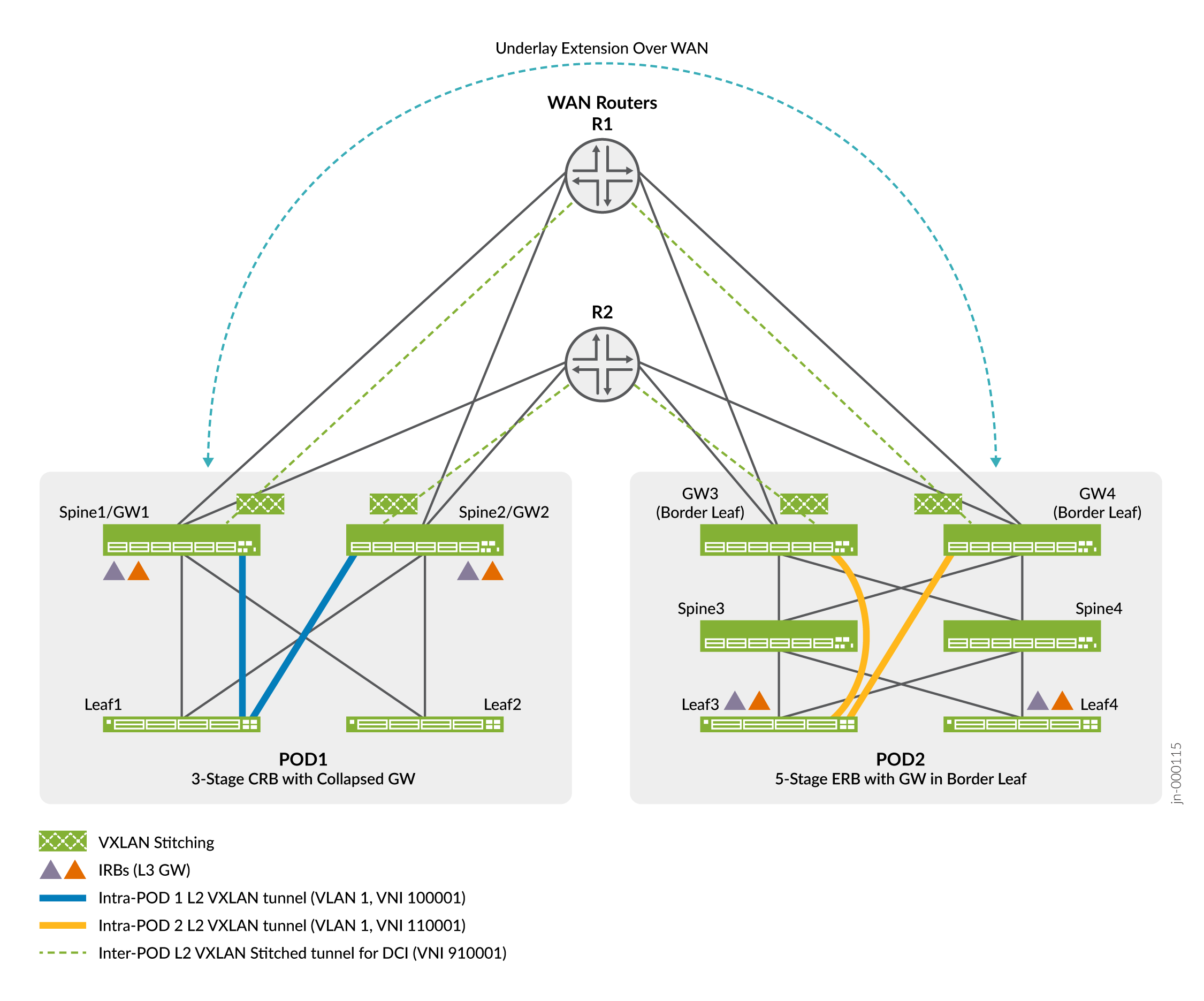
In Figure 1, each WAN router connects to each gateway device in both PODs. These connections and the related BGP peer sessions serve to extend the underlay between the two PODs. Specifically, the devices advertise the loopback addresses of the gateway devices between the PODs. This loopback reachability establishes an EBGP based peering session to extend the overlay between the gateway devices in both pods.
POD 1 represents a 3-stage CRB architecture with the gateway function collapsed into the spine devices. Thus, in POD 1 the terms spine and gateway are each applicable. In general we’ll use the term gateway when describing the spine devices as the focus here is on their gateway functionality.
POD 2, in contrast, is a 5-stage ERB architecture with lean spines and discrete gateway devices. The gateway devices in POD 2 can also be called super-spine or border leaf devices. In the context of this example, they perform the VXLAN stitching functionality and so we refer to them as gateway devices.
Table 1 outlines the POD architectures we validated as part of this reference design.
|
POD 1 |
POD 2 |
|---|---|
|
Edge-Routed Bridging |
Edge-Routed Bridging |
|
Centrally-Routed Bridging |
Edge-Routed Bridging |
|
Centrally-Routed Bridging |
Centrally-Routed Bridging |
|
Bridged Overlay |
Bridged Overlay |
|
3 or 5 stage fabric |
3 or 5 stage fabric |
Other items to note when using VXLAN stitching include:
-
You can combine the role of spine and gateway into a collapsed design as shown for POD 1.
-
The stitched VNI can have the same value (global stitching) when the PODs have overlapping VLAN to VNI assignments, or can be translated between the two PODs. The latter capability is useful when merging PODs (DCs) that don’t have overlapping VNI to VLAN assignments.
-
We support VXLAN stitching in the default-switch EVPN instance (EVI) and in MAC-VRF routing instances.
-
We support Layer 2 stitching for unicast and BUM traffic only. With BUM traffic, the designated forwarder (DF) for the local gateway ESI LAG performs ingress replication and forwards a copy of the BUM traffic to each remote gateway. At the remote gateway devices, the DF for the remote ESI LAG performs ingress replication and sends a copy of the BUM traffic to all leaf nodes in the local POD.
-
We recommend that you configure the IRB interfaces on the spine devices in a CRB fabric with the
proxy-macip-advertisementconfiguration statement. This option ensures correct ARP operation over a CRB EVPN-VXLAN fabric and is part of the CRB reference architecture. See proxy-mac-ip-advertisement for more information on this option.
Note the following about the EVPN–VXLAN fabric reference design:
-
This example assumes that the tiers of spine and leaf devices in the two PODs already exist and are up and running. As a result, this topic provides the configuration for the gateway to WAN router EBGP underlay peering, the inter-POD EBGP overlay peering, and the configuration needed for VXLAN stitching.
For information about configuring the spine and leaf devices in the two PODs, see the following:
-
This example integrates the WAN routers into an existing two POD EVPN-VXLAN fabric. To keep the focus on VXLAN stitching, both PODs in the example use the same 3-stage Clos fabric based on a CRB architecture. In addition to their role as Layer 3 VXLAN gateways, the spines also perform the VXLAN stitching function. The result is an example of a collapsed gateway architecture.
Figure 2 shows the collapsed gateway CRB based VXLAN stitching example topology.
Figure 2: VXLAN Stitching Example Topology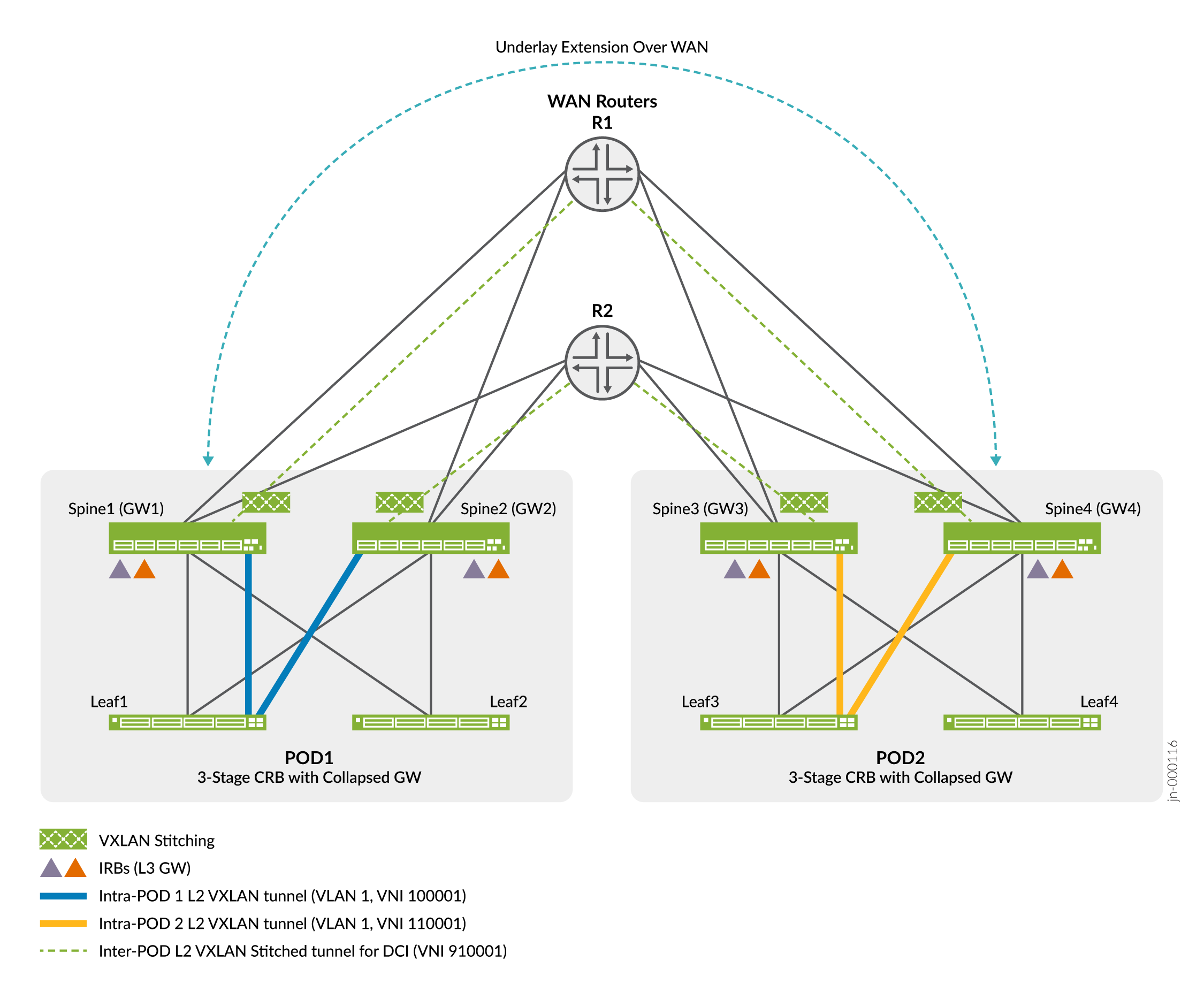
In this example, you add the gateway functionality to a pre-existing CRB spine configuration. As noted above, we also support 5-stage architectures with the super-spine layer performing the gateway peering and stitching functions. We recommend using a discrete gateway device for maximum scaling and performance. With a 3-stage or 5-stage ERB architecture, you add the gateway configuration to the lean spine or super spine devices, respectively.
-
When configuring the overlay BGP peering between the PODs, you can use either IBGP or EBGP. Typically, you use IBGP if your data centers (PODs) use the same autonomous system (AS) number and EBGP if your PODs use different AS numbers. Our example uses different AS numbers in each POD, therefore EBGP peering is used to extend the overlay between the PODs.
-
After you integrate the WAN routers to extend the underlay and overlay between the two PODs, you configure translational VXLAN stitching to extend a given VLAN between the PODs. Translational VXLAN stitching translates the VNI value used locally in each POD to a common VNI value used across the WAN segment. Note that in our example, we assign VLAN 1 a different (non-overlapping) VNI value in each POD. This is why we use translational stitching in this case. You normally use global mode stitching when the same VNI value is mapped to the same VLAN in both PODS.
Configure Gateway Devices to Extend the Underlay Over the WAN
This section shows you how to configure the collapsed gateway devices (a CRB spine with added VXLAN stitching gateway functionality) so they can communicate with the WAN devices. Recall that each POD already has a fully functional underlay and CRB overlay based on the reference implementation for a 3-stage CRB architecture. See Centrally-Routed Bridging Overlay Design and Implementation for details.
You configure the spine/gateway devices to peer with the WAN routers to extend the underlay between the two PODs. This involves configuring EBGP peering and policy to tag and advertise the loopback routes from each gateway. These routes establish the inter-POD EBGP peering sessions that extend the fabric overlay in the next section.
Configuring the WAN routers is outside the scope of this document. They simply need to support aggregate Ethernet interfaces and EBGP peering to the gateway devices. In this example the WAN routers must re-advertise all routes received from one POD to the other. In the case of a Junos device, this is the default policy for the EBGP underlay peering in this example.
Figure 3 provides the details regarding interfaces, IP addressing, and AS numbering for the DCI portion of the POD networks.
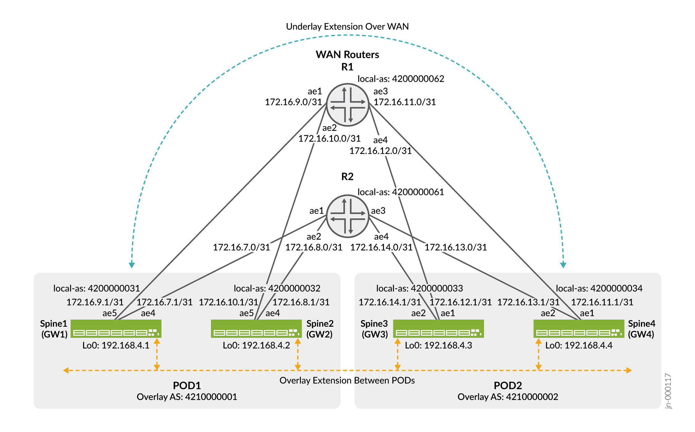
The configuration on all the gateway devices is similar. We’ll walk you through configuring the gateway 1 device and then provide the full configuration delta for the other 3 gateways.
Gateway 1
Configure Gateway Devices to Extend the Overlay Over the WAN
This section show how to extend the EVPN overlay between the two PODs using EBGP. Recall that in this example the two PODs have unique AS numbers, so EBGP is used.
As is typical for 3-stage CRB fabric, our spine devices (gateways) function as route reflectors in the overlay for the leaf devices in their respective PODs. In this section you define a new EBGP peering group that extends the overlay between the PODs. See Figure 3 for details about the AS numbering and spine device loopback addresses.
The configuration on all the gateway devices is similar. Once again, we’ll walk you through configuring the gateway 1 device, and provide the full configuration delta for the other 3 gateways.
Gateway 1
Gateway Device Configurations for Underlay and Overlay Extension
This section provides the configuration delta for all four gateway devices. You add this delta to the initial CRB baseline to extend the POD underlay and overlay over the WAN.
The final two statements modify the existing fabric underlay policy to block re-advertisement of routes tagged with the wan_underlay_comm community from the other leaf devices.
Gateway 1 (POD 1)
set interfaces et-0/0/1 ether-options 802.3ad ae4 set interfaces ae4 unit 0 family inet address 172.16.7.1/31 set interfaces et-0/0/2 ether-options 802.3ad ae5 set interfaces ae5 unit 0 family inet address 172.16.9.1/31 set protocols bgp group underlay-bgp-wan type external set protocols bgp group underlay-bgp-wan local-as 4200000031 set protocols bgp group underlay-bgp-wan neighbor 172.16.7.0 peer-as 4200000061 set protocols bgp group underlay-bgp-wan neighbor 172.16.9.0 peer-as 4200000062 set policy-options policy-statement wan_import from community wan_underlay_comm set policy-options policy-statement wan_import then local-preference subtract 10 set protocols bgp group underlay-bgp-wan import wan-import set policy-options policy-statement underlay-clos-export-wan term loopback from interface lo0.0 set policy-options policy-statement underlay-clos-export-wan term loopback then community add wan_underlay_comm set policy-options policy-statement underlay-clos-export-wan term loopback then accept set policy-options policy-statement underlay-clos-export-wan term def then reject set policy-options community wan_underlay_comm members 12345:12345 set protocols bgp group underlay-bgp-wan export underlay-clos-export-wan set protocols bgp group underlay-bgp-wan multipath multiple-as set protocols bgp group underlay-bgp-wan bfd-liveness-detection minimum-interval 1000 set protocols bgp group underlay-bgp-wan bfd-liveness-detection multiplier 3 set protocols bgp group underlay-bgp-wan bfd-liveness-detection session-mode automatic set protocols bgp group overlay-ebgp-extn-dci type external set protocols bgp group overlay-ebgp-extn-dci multihop no-nexthop-change set protocols bgp group overlay-ebgp-extn-dci local-address 192.168.4.1 set protocols bgp group overlay-ebgp-extn-dci family evpn signaling delay-route-advertisements minimum-delay routing-uptime 400 set protocols bgp group overlay-ebgp-extn-dci family route-target external-paths 2 set protocols bgp group overlay-ebgp-extn-dci local-as 4210000001 set protocols bgp group overlay-ebgp-extn-dci multipath multiple-as set protocols bgp group overlay-ebgp-extn-dci neighbor 192.168.4.3 peer-as 4210000002 set protocols bgp group overlay-ebgp-extn-dci neighbor 192.168.4.4 peer-as 4210000002 set protocols bgp group overlay-ebgp-extn-dci bfd-liveness-detection minimum-interval 4000 set protocols bgp group overlay-ebgp-extn-dci bfd-liveness-detection multiplier 3 set protocols bgp group overlay-ebgp-extn-dci bfd-liveness-detection session-mode automatic set policy-options policy-statement underlay-clos-export term from_wan from community underlay-clos-export set policy-options policy-statement underlay-clos-export term from_wan then reject
Gateway 2 (Pod 1)
set interfaces et-0/0/1 ether-options 802.3ad ae4
set interfaces ae4 unit 0 family inet address 172.16.8.1/31
set interfaces et-0/0/2 ether-options 802.3ad ae5
set interfaces ae5 unit 0 family inet address 172.16.10.1/31
set protocols bgp group underlay-bgp-wan type external
set protocols bgp group underlay-bgp-wan local-as 4200000032
set protocols bgp group underlay-bgp-wan neighbor 172.16.8.0 peer-as 4200000061
set protocols bgp group underlay-bgp-wan neighbor 172.16.10.0 peer-as 4200000062
set policy-options policy-statement wan_import from community wan_underlay_comm
set policy-options policy-statement wan_import then local-preference subtract 10
set protocols bgp group underlay-bgp-wan import wan-import
set policy-options policy-statement underlay-clos-export-wan term loopback from interface lo0.0
set policy-options policy-statement underlay-clos-export-wan term loopback then community add wan_underlay_comm
set policy-options policy-statement underlay-clos-export-wan term loopback then accept
set policy-options policy-statement underlay-clos-export-wan term def then reject
set policy-options community wan_underlay_comm members 12345:12345
set protocols bgp group underlay-bgp-wan export underlay-clos-export-wan
set protocols bgp group underlay-bgp-wan multipath multiple-as
set protocols bgp group underlay-bgp-wan bfd-liveness-detection minimum-interval 1000
set protocols bgp group underlay-bgp-wan bfd-liveness-detection multiplier 3
set protocols bgp group underlay-bgp-wan bfd-liveness-detection session-mode automatic

set protocols bgp group overlay-ebgp-extn-dci type external
set protocols bgp group overlay-ebgp-extn-dci multihop no-nexthop-change
set protocols bgp group overlay-ebgp-extn-dci local-address 192.168.4.2
set protocols bgp group overlay-ebgp-extn-dci family evpn signaling delay-route-advertisements minimum-delay routing-uptime 400
set protocols bgp group overlay-ebgp-extn-dci family route-target external-paths 2
set protocols bgp group overlay-ebgp-extn-dci local-as 4210000001
set protocols bgp group overlay-ebgp-extn-dci multipath multiple-as
set protocols bgp group overlay-ebgp-extn-dci neighbor 192.168.4.3 peer-as 4210000002
set protocols bgp group overlay-ebgp-extn-dci neighbor 192.168.4.4 peer-as 4210000002
set protocols bgp group overlay-ebgp-extn-dci bfd-liveness-detection minimum-interval 4000
set protocols bgp group overlay-ebgp-extn-dci bfd-liveness-detection multiplier 3
set protocols bgp group overlay-ebgp-extn-dci bfd-liveness-detection session-mode automatic

set policy-options policy-statement underlay-clos-export term from_wan from community underlay-clos-export
set policy-options policy-statement underlay-clos-export term from_wan then reject
Gateway 3 (POD 2)
set interfaces et-0/0/1 ether-options 802.3ad ae1
set interfaces ae1 unit 0 family inet address 172.16.12.1/31
set interfaces et-0/0/2 ether-options 802.3ad ae2
set interfaces ae2 unit 0 family inet address 172.16.14.1/31
set protocols bgp group underlay-bgp-wan type external
set protocols bgp group underlay-bgp-wan local-as 4200000033
set protocols bgp group underlay-bgp-wan neighbor 172.16.12.0 peer-as 4200000062
set protocols bgp group underlay-bgp-wan neighbor 172.16.14.0 peer-as 4200000061
set policy-options policy-statement wan_import from community wan_underlay_comm
set policy-options policy-statement wan_import then local-preference subtract 10
set protocols bgp group underlay-bgp-wan import wan-import
set policy-options policy-statement underlay-clos-export-wan term loopback from interface lo0.0
set policy-options policy-statement underlay-clos-export-wan term loopback then community add wan_underlay_comm
set policy-options policy-statement underlay-clos-export-wan term loopback then accept
set policy-options policy-statement underlay-clos-export-wan term def then reject
set policy-options community wan_underlay_comm members 12345:12345
set protocols bgp group underlay-bgp-wan export underlay-clos-export-wan
set protocols bgp group underlay-bgp-wan multipath multiple-as
set protocols bgp group underlay-bgp-wan bfd-liveness-detection minimum-interval 1000
set protocols bgp group underlay-bgp-wan bfd-liveness-detection multiplier 3
set protocols bgp group underlay-bgp-wan bfd-liveness-detection session-mode automatic

set protocols bgp group overlay-ebgp-extn-dci type external
set protocols bgp group overlay-ebgp-extn-dci multihop no-nexthop-change
set protocols bgp group overlay-ebgp-extn-dci local-address 192.168.4.3
set protocols bgp group overlay-ebgp-extn-dci family evpn signaling delay-route-advertisements minimum-delay routing-uptime 400
set protocols bgp group overlay-ebgp-extn-dci family route-target external-paths 2
set protocols bgp group overlay-ebgp-extn-dci local-as 4210000002
set protocols bgp group overlay-ebgp-extn-dci multipath multiple-as
set protocols bgp group overlay-ebgp-extn-dci neighbor 192.168.4.1 peer-as 4210000001
set protocols bgp group overlay-ebgp-extn-dci neighbor 192.168.4.2 peer-as 4210000001
set protocols bgp group overlay-ebgp-extn-dci bfd-liveness-detection minimum-interval 4000
set protocols bgp group overlay-ebgp-extn-dci bfd-liveness-detection multiplier 3
set protocols bgp group overlay-ebgp-extn-dci bfd-liveness-detection session-mode automatic

set policy-options policy-statement underlay-clos-export term from_wan from community underlay-clos-export
set policy-options policy-statement underlay-clos-export term from_wan then reject
Gateway 4 (POD 2)
set interfaces et-0/0/1 ether-options 802.3ad ae1
set interfaces ae1 unit 0 family inet address 172.16.11.1/31
set interfaces et-0/0/2 ether-options 802.3ad ae2
set interfaces ae2 unit 0 family inet address 172.16.13.1/31
set protocols bgp group underlay-bgp-wan type external
set protocols bgp group underlay-bgp-wan local-as 4200000034
set protocols bgp group underlay-bgp-wan neighbor 172.16.11.0 peer-as 4200000062
set protocols bgp group underlay-bgp-wan neighbor 172.16.12.0 peer-as 4200000061
set policy-options policy-statement wan_import from community wan_underlay_comm
set policy-options policy-statement wan_import then local-preference subtract 10
set protocols bgp group underlay-bgp-wan import wan-import
set policy-options policy-statement underlay-clos-export-wan term loopback from interface lo0.0
set policy-options policy-statement underlay-clos-export-wan term loopback then community add wan_underlay_comm
set policy-options policy-statement underlay-clos-export-wan term loopback then accept
set policy-options policy-statement underlay-clos-export-wan term def then reject
set policy-options community wan_underlay_comm members 12345:12345
set protocols bgp group underlay-bgp-wan export underlay-clos-export-wan
set protocols bgp group underlay-bgp-wan multipath multiple-as
set protocols bgp group underlay-bgp-wan bfd-liveness-detection minimum-interval 1000
set protocols bgp group underlay-bgp-wan bfd-liveness-detection multiplier 3
set protocols bgp group underlay-bgp-wan bfd-liveness-detection session-mode automatic

set protocols bgp group overlay-ebgp-extn-dci type external
set protocols bgp group overlay-ebgp-extn-dci multihop no-nexthop-change
set protocols bgp group overlay-ebgp-extn-dci local-address 192.168.4.4
set protocols bgp group overlay-ebgp-extn-dci family evpn signaling delay-route-advertisements minimum-delay routing-uptime 400
set protocols bgp group overlay-ebgp-extn-dci family route-target external-paths 2
set protocols bgp group overlay-ebgp-extn-dci local-as 4210000002
set protocols bgp group overlay-ebgp-extn-dci multipath multiple-as
set protocols bgp group overlay-ebgp-extn-dci neighbor 192.168.4.1 peer-as 4210000001
set protocols bgp group overlay-ebgp-extn-dci neighbor 192.168.4.2 peer-as 4210000001
set protocols bgp group overlay-ebgp-extn-dci bfd-liveness-detection minimum-interval 4000
set protocols bgp group overlay-ebgp-extn-dci bfd-liveness-detection multiplier 3
set protocols bgp group overlay-ebgp-extn-dci bfd-liveness-detection session-mode automatic

set policy-options policy-statement underlay-clos-export term from_wan from community underlay-clos-export
set policy-options policy-statement underlay-clos-export term from_wan then reject
Verify Underlay and Overlay Extension Over the WAN
This section shows how you verify the gateway devices are properly integrated into the WAN to extend the underlay and overlay networks between the two PODs.
Configure Translational VXLAN Stitching DCI in the Default Switch Instance
In this section you configure VXLAN stitching in the gateway devices to provide Layer 2 stretch between the two PODs using the default switch instance. We support VXLAN stitching in the default switch instance and in MAC-VRF instances. We begin with the default switch instance, and later show the delta for the MAC-VRF instance case.
VXLAN stitching supports both a global mode and a translational mode. In the global mode, the VNI remains the same end-to-end, that is, across both the PODs and the WAN network. You use global mode when the VLAN and VNI assignments overlap between the PODs. In translational mode, you map a local POD VNI value to a VNI used across the WAN.
You configure VXLAN stitching only on the gateway devices. The leaf devices don’t require any changes. In ERB fabrics, the lean spine devices also don’t require any changes if you have a super-spine layer performing the gateway function.
Table 2 outlines the POD VLAN and VNI assignments. In this example, the PODs use a different VNI for the same VLAN. This is why you configure translational stitching in this case. With translational stitching, the VNI can be unique to each POD and still be stitched to a shared VNI assignment over the WAN.
|
POD 1 |
POD 2 |
WAN DCI |
|---|---|---|
|
VLAN 1 |
||
|
VNI: 100001 |
VNI: 110001 |
VNI: 910001 |
|
VLAN 2 |
||
|
VNI: 100002 |
VNI: 110002 |
VNI: 910002 |
Figure 4 provides a high-level view of the VXLAN stitching plan for VLAN 1 in our example.
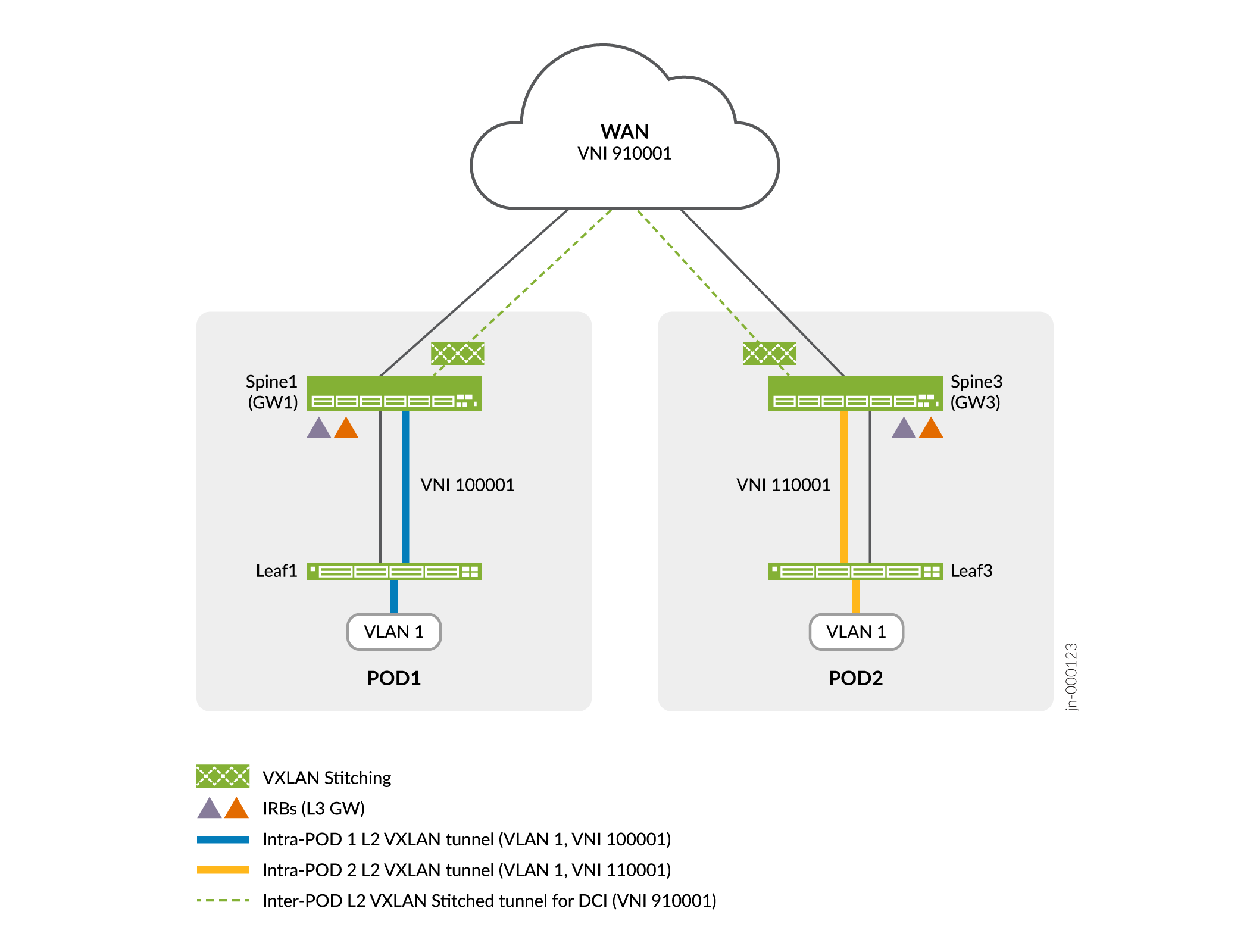
Figure 4 shows VLAN 1 in POD 1 uses VNI 100001, while the same VLAN in POD 2 maps to 11000. You stitch both VLANs to a common VNI 910001 for transport over the WAN. When received from the WAN, the gateway translates the stitched VNI back to the VNI used locally within its POD.
Once again, the configuration on the gateway devices is similar. We walk you through the steps needed on the gateway 1 device, and provide the configuration delta for the other gateway nodes.
Perform these steps to configure translational VXLAN stitching on gateway 1.
Gateway 1
Gateway Device Configurations for Translational VXLAN Stitching in Default Switch Instance
This section provides the configuration delta for all four gateway devices. You add this delta to the CRB baseline that you have modified for DCI over the WAN. Once you have extended the underlay and overlay, the following configurations perform translational VXLAN stitching between the local POD’s VNI and the VNI on the WAN.
Gateway 1 (POD 1)
set protocols evpn interconnect vrf-target target:60001:60001 set protocols evpn interconnect route-distinguisher 192.168.4.1:30000 set protocols evpn interconnect esi 00:00:ff:ff:00:11:00:00:00:01 set protocols evpn interconnect esi all-active set protocols evpn interconnect interconnected-vni-list 910001 set protocols evpn interconnect interconnected-vni-list 910002 set vlans EP-TYPE-2-VLAN-1 vxlan translation-vni 910001 set vlans EP-TYPE-2-VLAN-2 vxlan translation-vni 910002
Gateway 2 (Pod 1)
set protocols evpn interconnect vrf-target target:60001:60001
set protocols evpn interconnect route-distinguisher 192.168.4.2:30000
set protocols evpn interconnect esi 00:00:ff:ff:00:11:00:00:00:01
set protocols evpn interconnect esi all-active

set protocols evpn interconnect interconnected-vni-list 910001
set protocols evpn interconnect interconnected-vni-list 910002

set vlans EP-TYPE-2-VLAN-1 vxlan translation-vni 910001
set vlans EP-TYPE-2-VLAN-2 vxlan translation-vni 910002
Gateway 3 (POD 2)
set protocols evpn interconnect vrf-target target:60001:60001
set protocols evpn interconnect route-distinguisher 192.168.4.3:30000
set protocols evpn interconnect esi 00:00:ff:ff:00:22:00:00:00:01
set protocols evpn interconnect esi all-active

set protocols evpn interconnect interconnected-vni-list 910001
set protocols evpn interconnect interconnected-vni-list 910002

set vlans EP-TYPE-2-VLAN-1 vxlan translation-vni 910001
set vlans EP-TYPE-2-VLAN-2 vxlan translation-vni 910002
Gateway 4 (POD 2)
set protocols evpn interconnect vrf-target target:60001:60001
set protocols evpn interconnect route-distinguisher 192.168.4.4:30000
set protocols evpn interconnect esi 00:00:ff:ff:00:22:00:00:00:01
set protocols evpn interconnect esi all-active

set protocols evpn interconnect interconnected-vni-list 910001
set protocols evpn interconnect interconnected-vni-list 910002

set vlans EP-TYPE-2-VLAN-1 vxlan translation-vni 910001
set vlans EP-TYPE-2-VLAN-2 vxlan translation-vni 910002
Verify Translational VXLAN Stitching in Default Switch Instance
VXLAN Stitching in a MAC-VRF Routing Instance
We support both global and translational VXLAN stitching in MAC-VRF routing instances. Because we demonstrated translational stitching for the previous default switch instance, for the MAC-VRF case we show global mode VXLAN stitching.
Coverage of MAC-VRF routing instances is beyond the scope of this document. Once again, we assume you have a working CRB fabric with MAC-VRF instances configured as per the reference baseline. For details on configuring MAC-VRF, see MAC-VRF Routing Instance Type Overview and a sample use case at EVPN-VXLAN DC IP Fabric MAC VRF L2 services.
To keep the focus on the VXLAN stitching feature, we call out the delta for adding VXLAN
stitching to an existing MAC-VRF. As with the default switch instance, we apply the
stitching configuration only to the gateway devices. In the case of MAC-VRF, however, you
configure the VLAN to VNI mapping in the MAC-VRF instance, rather than at the
[edit vlans] hierarchy. Another difference in the MAC-VRF case is that
you configure the interconnected-vni-list statement in the routing
instance instead of at the [edit protocols evpn interconnect
interconnected-vni-list] hierarchy.
The goal in this example is to perform global VXLAN stitching for VLANs 1201 and 1202, which map to VXLAN VNIs 401201 and 401201, respectively. You configure the same VLAN to VNI mapping in both PODS. You can use global mode stitching because the VLAN to VNI assignments overlap in both PODs.
You add the following commands to the gateway devices for the MAC-VRF instance that will perform stitching. The configuration defines the ESI LAG used between the local gateways and specifies the list of interconnected VNIs.
You need a similar configuration on all gateway devices. As before, we walk though the configuration details for the gateway 1 device and then provide the complete configuration delta for the other gateways.
In the below example you configure VNIs 401201 and 401202 for VXLAN stitching over the WAN segment.
set routing-instances MACVRF-mac-vrf-ep-t2-stchd-1 protocols evpn interconnect vrf-target target:60005:60001
set routing-instances MACVRF-mac-vrf-ep-t2-stchd-1 protocols evpn interconnect route-distinguisher 192.168.4.1:46000
set routing-instances MACVRF-mac-vrf-ep-t2-stchd-1 protocols evpn interconnect esi 00:00:ff:ff:00:11:00:04:00:01
set routing-instances MACVRF-mac-vrf-ep-t2-stchd-1 protocols evpn interconnect esi all-active
set routing-instances MACVRF-mac-vrf-ep-t2-stchd-1 protocols evpn interconnect interconnected-vni-list 401201
set routing-instances MACVRF-mac-vrf-ep-t2-stchd-1 protocols evpn interconnect interconnected-vni-list 401202
When configuring VXLAN stitching in a MAC-VRF context, you must include the set
forwarding-options evpn-vxlan shared-tunnels option on all leaf nodes in the
QFX5000 line of switches running Junos OS. After adding this statement, you must reboot
the switch. We don’t recommend using the shared tunnels statement on
gateway nodes in the QFX10000 line of switches running Junos OS with VXLAN stitching in
MAC-VRF routing instances.
Shared tunnels are enabled by default on devices running Junos OS Evolved (which supports EVPN-VXLAN only with MAC-VRF configurations).
As noted, a complete MAC-VRF routing instance configuration is beyond our scope. The configuration block below uses a pre-existing MAC-VRF instance based on the MAC-VRF reference design. We show this configuration snip to better illustrate why this is an example of global mode VXLAN stitching (for a MAC-VRF instance). The sample is from the CRB spine 1 device, which is also a gateway in our collapsed gateway example topology. For brevity, we only show the configuration for VLAN 1201.
user@Spine-1> show configuration routing-instances MACVRF-mac-vrf-ep-t2-stchd-1 vlans EP-TYPE-2-VLAN-1201
vlan-id 1201;
l3-interface irb.1201;
vxlan {
    vni 401201;
}
In the above, the MAC-VRF definition for VLAN 1201 specifies the same VNI (401201) listed
at the [edit routing-instances MACVRF-mac-vrf-ep-t2-stchd-1 protocols evpn
interconnect interconnected-vni-list] hierarchy. This results in end-to-end
(global) significance for that VNI.
As with the default switch instance, it is trivial to invoke translational VXLAN stitching in the MAC-VRF context.
For example, to translate from local VNI 300801 for VLAN 801 to a WAN VNI of 920001, you
simply modify the VLAN definition in the related MAC-VRF instance to include the
translation-vni 920001 statement.
user@Spine-1>show routing-instances MACVRF-mac-vrf-ep-t2-stchd-transl-1 vlans EP-TYPE-2-VLAN-801
vlan-id 801;
l3-interface irb.801;
vxlan {
    vni 300801;
    translation-vni 920001
}
By adding the translation-vni 920001 statement to the MAC-VRF VLAN
configuration, you tell the gateway device to translate from local VNI 300801 to VNI
920001 when sending over the WAN.
Gateway Device Configurations for Global VXLAN Stitching With MAC-VRF
This section provides the configuration delta for all four gateway devices to support
global mode VXLAN stitching in a MAC-VRF context. You add this delta is added to the CRB
baseline you modified for DCI over the WAN. After you extend the underlay and overlay, the
configurations below perform global VXLAN stitching for VNIs 401201 and 401202. Because
this is global mode example, you don’t include the translation-vni
statement. The VLAN and interconnect VNI values are the same.
Gateway 1 (POD 1)
set routing-instances MACVRF-mac-vrf-ep-t2-stchd-1 protocols evpn interconnect vrf-target target:60005:60001
set routing-instances MACVRF-mac-vrf-ep-t2-stchd-1 protocols evpn interconnect route-distinguisher 192.168.4.1:46000
set routing-instances MACVRF-mac-vrf-ep-t2-stchd-1 protocols evpn interconnect esi 00:00:ff:ff:00:11:00:04:00:01
set routing-instances MACVRF-mac-vrf-ep-t2-stchd-1 protocols evpn interconnect esi all-active

set routing-instances MACVRF-mac-vrf-ep-t2-stchd-1 protocols evpn interconnect interconnected-vni-list 401201
set routing-instances MACVRF-mac-vrf-ep-t2-stchd-1 protocols evpn interconnect interconnected-vni-list 401202

set routing-instances MACVRF-mac-vrf-ep-t2-stchd-1 vlans EP-TYPE-2-VLAN- vlan-id 1201
set routing-instances MACVRF-mac-vrf-ep-t2-stchd-1 vlans EP-TYPE-2-VLAN-1201 l3-interface irb.1201
set routing-instances MACVRF-mac-vrf-ep-t2-stchd-1 vlans EP-TYPE-2-VLAN-1201 vxlan vni 401201
set routing-instances MACVRF-mac-vrf-ep-t2-stchd-1 vlans EP-TYPE-2-VLAN-1202 vlan-id 1202
set routing-instances MACVRF-mac-vrf-ep-t2-stchd-1 vlans EP-TYPE-2-VLAN-1202 l3-interface irb.1202
set routing-instances MACVRF-mac-vrf-ep-t2-stchd-1 vlans EP-TYPE-2-VLAN-1202 vxlan vni 401202
Gateway 2 (Pod 1)
set routing-instances MACVRF-mac-vrf-ep-t2-stchd-1 protocols evpn interconnect vrf-target target:60005:60001
set routing-instances MACVRF-mac-vrf-ep-t2-stchd-1 protocols evpn interconnect route-distinguisher 192.168.4.2:46000
set routing-instances MACVRF-mac-vrf-ep-t2-stchd-1 protocols evpn interconnect esi 00:00:ff:ff:00:11:00:04:00:01
set routing-instances MACVRF-mac-vrf-ep-t2-stchd-1 protocols evpn interconnect esi all-active

set routing-instances MACVRF-mac-vrf-ep-t2-stchd-1 protocols evpn interconnect interconnected-vni-list 401201
set routing-instances MACVRF-mac-vrf-ep-t2-stchd-1 protocols evpn interconnect interconnected-vni-list 401202

set routing-instances MACVRF-mac-vrf-ep-t2-stchd-1 vlans EP-TYPE-2-VLAN- vlan-id 1201
set routing-instances MACVRF-mac-vrf-ep-t2-stchd-1 vlans EP-TYPE-2-VLAN-1201 l3-interface irb.1201
set routing-instances MACVRF-mac-vrf-ep-t2-stchd-1 vlans EP-TYPE-2-VLAN-1201 vxlan vni 401201
set routing-instances MACVRF-mac-vrf-ep-t2-stchd-1 vlans EP-TYPE-2-VLAN-1202 vlan-id 1202
set routing-instances MACVRF-mac-vrf-ep-t2-stchd-1 vlans EP-TYPE-2-VLAN-1202 l3-interface irb.1202
set routing-instances MACVRF-mac-vrf-ep-t2-stchd-1 vlans EP-TYPE-2-VLAN-1202 vxlan vni 401202
Gateway 3 (POD 2)
set routing-instances MACVRF-mac-vrf-ep-t2-stchd-1 protocols evpn interconnect vrf-target target:60005:60001
set routing-instances MACVRF-mac-vrf-ep-t2-stchd-1 protocols evpn interconnect route-distinguisher 192.168.4.3:46000
set routing-instances MACVRF-mac-vrf-ep-t2-stchd-1 protocols evpn interconnect esi 00:00:ff:ff:00:22:00:04:00:01
set routing-instances MACVRF-mac-vrf-ep-t2-stchd-1 protocols evpn interconnect esi all-active

set routing-instances MACVRF-mac-vrf-ep-t2-stchd-1 protocols evpn interconnect interconnected-vni-list 401201
set routing-instances MACVRF-mac-vrf-ep-t2-stchd-1 protocols evpn interconnect interconnected-vni-list 401202

set routing-instances MACVRF-mac-vrf-ep-t2-stchd-1 vlans EP-TYPE-2-VLAN- vlan-id 1201
set routing-instances MACVRF-mac-vrf-ep-t2-stchd-1 vlans EP-TYPE-2-VLAN-1201 l3-interface irb.1201
set routing-instances MACVRF-mac-vrf-ep-t2-stchd-1 vlans EP-TYPE-2-VLAN-1201 vxlan vni 401201
set routing-instances MACVRF-mac-vrf-ep-t2-stchd-1 vlans EP-TYPE-2-VLAN-1202 vlan-id 1202
set routing-instances MACVRF-mac-vrf-ep-t2-stchd-1 vlans EP-TYPE-2-VLAN-1202 l3-interface irb.1202
set routing-instances MACVRF-mac-vrf-ep-t2-stchd-1 vlans EP-TYPE-2-VLAN-1202 vxlan vni 401202
Gateway 4 (POD 2)
set routing-instances MACVRF-mac-vrf-ep-t2-stchd-1 protocols evpn interconnect vrf-target target:60005:60001
set routing-instances MACVRF-mac-vrf-ep-t2-stchd-1 protocols evpn interconnect route-distinguisher 192.168.4.4:46000
set routing-instances MACVRF-mac-vrf-ep-t2-stchd-1 protocols evpn interconnect esi 00:00:ff:ff:00:22:00:04:00:01
set routing-instances MACVRF-mac-vrf-ep-t2-stchd-1 protocols evpn interconnect esi all-active

set routing-instances MACVRF-mac-vrf-ep-t2-stchd-1 protocols evpn interconnect interconnected-vni-list 401201
set routing-instances MACVRF-mac-vrf-ep-t2-stchd-1 protocols evpn interconnect interconnected-vni-list 401202

set routing-instances MACVRF-mac-vrf-ep-t2-stchd-1 vlans EP-TYPE-2-VLAN- vlan-id 1201
set routing-instances MACVRF-mac-vrf-ep-t2-stchd-1 vlans EP-TYPE-2-VLAN-1201 l3-interface irb.1201
set routing-instances MACVRF-mac-vrf-ep-t2-stchd-1 vlans EP-TYPE-2-VLAN-1201 vxlan vni 401201
set routing-instances MACVRF-mac-vrf-ep-t2-stchd-1 vlans EP-TYPE-2-VLAN-1202 vlan-id 1202
set routing-instances MACVRF-mac-vrf-ep-t2-stchd-1 vlans EP-TYPE-2-VLAN-1202 l3-interface irb.1202
set routing-instances MACVRF-mac-vrf-ep-t2-stchd-1 vlans EP-TYPE-2-VLAN-1202 vxlan vni 401202
When configuring VXLAN stitching in a MAC-VRF context, you must include the set
forwarding-options evpn-vxlan shared-tunnels option on all leaf nodes in the
QFX5000 line of switches. After adding this statement you must reboot the switch. We
don’t recommend configuring the shared tunnel statement on gateway nodes in the QFX10000
line of switches running Junos OS with VXLAN stitching in MAC-VRF routing instances.
Shared tunnels are enabled by default on devices running Junos OS Evolved (which supports EVPN-VXLAN only with MAC-VRF configurations).
Verify Global VXLAN Stitching in a MAC-VRF Instance
Virtual Machine Traffic Optimization (VMTO) with VXLAN Stitching
In some environments you may want to install /32 or /128 host routes to optimize traffic to a specific VM. When you use VXLAN stitching, configure the following on all gateway nodes to enable installation of host routes.
The first command adds host route support to the default switch instance. The second adds host route support for a specific MAC-VRF instance. You must configure both if you are using a mix of instance types.
set protocols evpn remote-ip-host-routes
set routing-instances MACVRF-mac-vrf-ep-t2-stchd-1 protocols evpn remote-ip-host-routes
Verify Host Route Support
Purpose
Confirm that /32 host routes are imported into a Layer 3 VRF table when using the default switch instance or a MAC-VRF table when using MAC-VRF.
Action
Display the related routing instance’s route table and look for routes with a /32 (or /128) bit prefix. We begin with the display of a Layer 3 VRF table used with VXLAN stitching, the default switch instance:
user@Spine-1> show route table VRF-ep-t2-stchd-transl-1.inet.0 protocol evpn
VRF-ep-t2-stchd-transl-1.inet.0: 52 destinations, 56 routes (52 active, 0 holddown, 0 hidden)
+ = Active Route, - = Last Active, * = Both

10.0.1.1/32        *[EVPN/7] 23:54:12
                    >  via irb.1
10.0.1.11/32       *[EVPN/7] 23:54:12
                    >  via irb.1
10.0.1.101/32      *[EVPN/7] 23:54:12
                    >  via irb.1
10.0.1.111/32      *[EVPN/7] 23:54:12

. . .
Next, we display a MAC-VRF instance route table.
user@Spine-1> show route table VRF-mac-vrf-ep-t2-stchd-1.inet.0 protocol evpn
VRF-mac-vrf-ep-t2-stchd-1.inet.0: 52 destinations, 52 routes (52 active, 0 holddown, 0 hidden)
+ = Active Route, - = Last Active, * = Both

10.4.177.1/32      *[EVPN/7] 20:39:31
                    >  via irb.1201
10.4.177.11/32     *[EVPN/7] 23:57:20
                    >  via irb.1201
10.4.177.101/32    *[EVPN/7] 23:57:20
. . .