Help us improve your experience.

Let us know what you think.

Do you have time for a two-minute survey?


Bridged Overlay Design and Implementation

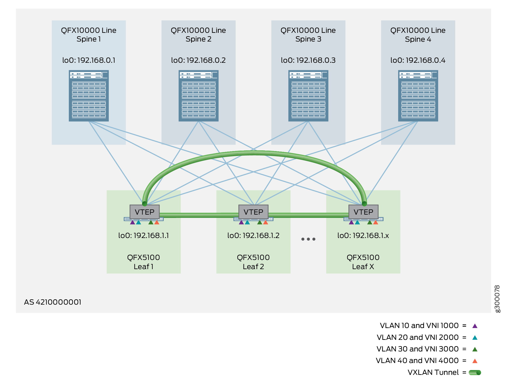
A bridged overlay provides Ethernet bridging between leaf devices in an EVPN network, as shown in Figure 1. This overlay type simply extends VLANs between the leaf devices across VXLAN tunnels. Bridged overlays provide an entry level overlay style for data center networks that require Ethernet connectivity but do not need routing services between the VLANs.

In this example, loopback interfaces on the leaf devices act as VXLAN tunnel endpoints (VTEPs). The tunnels enable the leaf devices to send VLAN traffic to other leaf devices and Ethernet-connected end systems in the data center. The spine devices only provide basic EBGP underlay and IBGP overlay connectivity for these leaf-to-leaf VXLAN tunnels.

Figure 1: Bridged OverlayBridged Overlay
Note:

If inter-VLAN routing is required for a bridged overlay, you can use an MX Series router or SRX Series security device that is external to the EVPN/VXLAN fabric. Otherwise, you can select one of the other overlay types that incorporate routing (such as an edge-routed bridging overlay, a centrally-routed bridging overlay, or a routed overlay) discussed in this Cloud Data Center Architecture Guide.

The following sections provide the detailed steps of how to configure a bridged overlay:

Configuring a Bridged Overlay

Bridged overlays are supported on all platforms included in this reference design. To configure a bridged overlay, you configure VNIs, VLANs, and VTEPs on the leaf devices, and BGP on the spine devices. We support either an IPv4 Fabric or an IPv6 Fabric (with supported platforms) as the fabric infrastructure with bridged overlay architectures.

When you implement this style of overlay on a spine device, the focus is on providing overlay transport services between the leaf devices. Consequently, you configure an IP Fabric underlay and IBGP overlay peering with IPv4, or an IPv6 Fabric underlay with EBGP IPv6 overlay peering. There are no VTEPs or IRB interfaces needed, because the spine device does not provide any routing functionality or EVPN/VXLAN capabilities in a bridged overlay.

On the leaf devices, you can configure a bridged overlay using the default switch instance or using MAC-VRF instances.

Note:

We support EVPN-VXLAN on devices running Junos OS Evolved only with MAC-VRF instance configurations.

In addition, we support the IPv6 Fabric infrastructure design only with MAC-VRF instance configurations.

Some configuration steps that affect the Layer 2 configuration differ with MAC-VRF instances. Likewise, one or two steps might differ for IPv6 Fabric configurations compared to IPv4 Fabric configurations. The leaf device configuration includes the following steps:

  • Enable EVPN with VXLAN encapsulation to connect to other leaf devices, and configure the loopback interface as a VTEP source interface. If you are using MAC-VRF instances instead of the default switching instance, configure a MAC-VRF instance with these parameters in the MAC-VRF instance. If your fabric uses an IPv6 Fabric, you configure the VTEP source interface as an IPv6 interface.

  • Establish route targets and route distinguishers. If you are using MAC-VRF instances instead of the default switching instance, configure a MAC-VRF instance with these parameters in the MAC-VRF instance.

  • Configure Ethernet Segment Identifier (ESI) settings.

  • Map VLANs to VNIs.

Again, you do not include IRB interfaces or routing on the leaf devices for this overlay method.

The following sections provide the detailed steps of how to configure and verify the bridged overlay:

Configuring a Bridged Overlay on the Spine Device

To configure a bridged overlay on a spine device, perform the following steps:

Note:

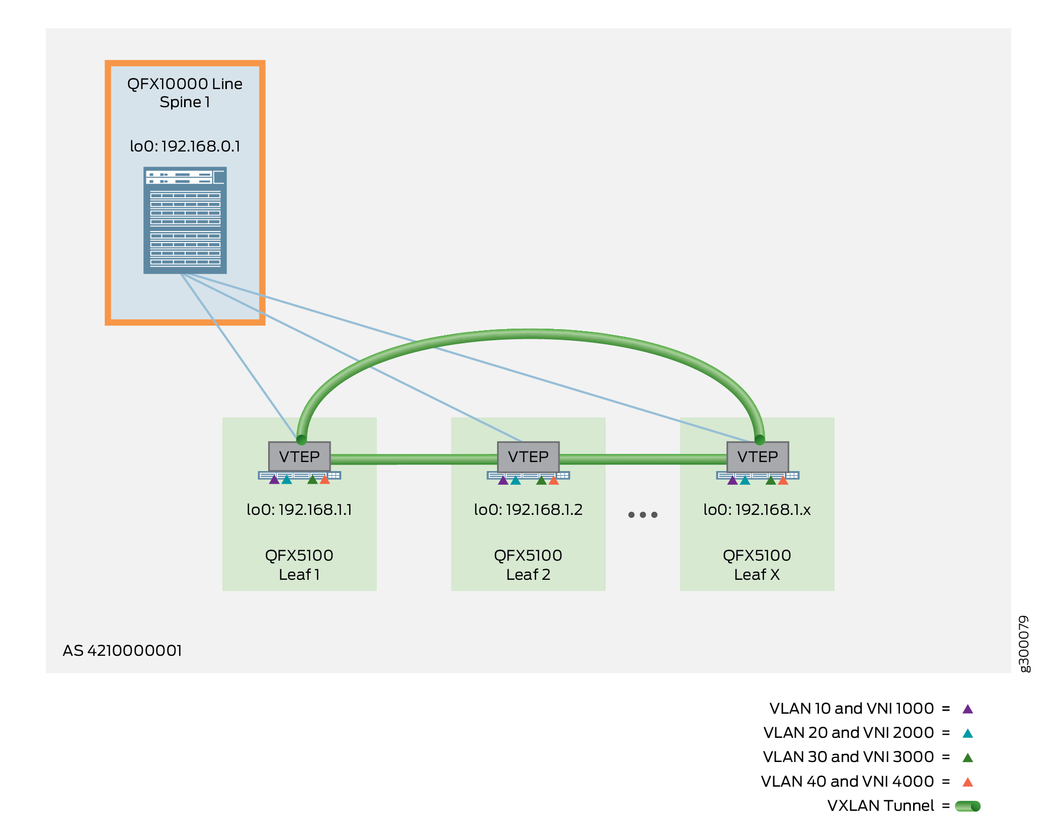
The following example shows the configuration for Spine 1, as shown in Figure 2.

Figure 2: Bridged Overlay – Spine DeviceBridged Overlay – Spine Device
  1. Ensure the IP fabric underlay is in place. To configure an IP fabric on a spine device, see IP Fabric Underlay Network Design and Implementation.

    If you are using an IPv6 Fabric, see IPv6 Fabric Underlay and Overlay Network Design and Implementation with EBGP instead. Those instructions include how to configure the IPv6 underlay connectivity with EBGP and IPv6 overlay peering.

  2. Confirm that your IBGP overlay is up and running. To configure an IBGP overlay on your spine devices, see Configure IBGP for the Overlay.

    If you are using an IPv6 Fabric, you don’t need this step. Step 1 also covers how to configure the EBGP IPv6 overlay peering that corresponds to the IPv6 underlay connectivity configuration.

Verifying a Bridged Overlay on the Spine Device

Issue the following commands to verify that the overlay is working properly on your spine devices:

  1. Verify that the spine device has reachability to the leaf devices. This output shows the possible routes to Leaf 1.

    (With an IPv6 Fabric, enter this command with the IPv6 address of the spine device instead of an IPv4 address.)

  2. Verify that IBGP is functional on the spine devices acting as a route reflector cluster. You should see peer relationships with all spine device loopback interfaces (192.168.0.1 through 192.168.0.4) and all leaf device loopback interfaces (192.168.1.1 through 192.168.1.96).

    Use the same command if you have an IPv6 Fabric with EBGP IPv6 overlay peering. In the output, look for the IPv6 addresses of the peer device interconnecting interfaces to verify underlay EBGP connectivity. Look for peer device loopback addresses to verify overlay EBGP peering. Ensure that the state is Establ (established).

Configuring a Bridged Overlay on the Leaf Device

To configure a bridged overlay on a leaf device, perform the following:

Note:
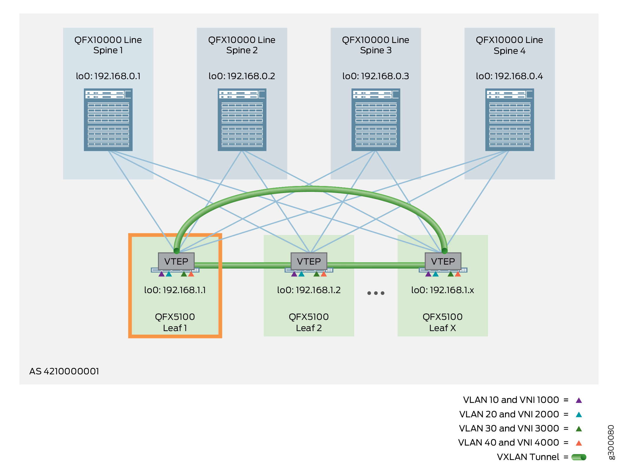
  • The following example shows the configuration for Leaf 1, as shown in Figure 3.

Figure 3: Bridged Overlay – Leaf DeviceBridged Overlay – Leaf Device
  1. Configure the IP Fabric underlay and overlay:

    For an IP Fabric underlay using IPv4:

    For an IPv6 Fabric underlay with EBGP IPv6 overlay peering:

  2. Configure the EVPN protocol with VXLAN encapsulation, and specify the VTEP source interface (in this case, the loopback interface of the leaf device).

    If your configuration uses the default instance, you configure EVPN-VXLAN at the global level. You also specify the VTEP source interface at the [edit switch-options] hierarchy level:

    Leaf 1 (Default Instance):

    If your configuration uses MAC-VRF instances, define a routing instance of type mac-vrf. Then configure EVPN-VXLAN and the VTEP source interface at that MAC-VRF routing instance hierarchy level. You also must configure a service type for the MAC-VRF instance. We configure the vlan-aware service type so you can associate multiple VLANs with the MAC-VRF instance. This setting is consistent with the alternative configuration that uses the default instance.

    Leaf 1 (MAC-VRF Instance):

    If you have an IPv6 Fabric infrastructure (supported only with MAC-VRF instances), in this step you include the inet6 option when you configure the VTEP source interface to use the device loopback address. This option enables IPv6 VXLAN tunneling in the fabric. This is the only difference in the MAC-VRF instance configuration with an IPv6 Fabric as compared to the MAC-VRF instance configuration with an IPv4 Fabric.

    Leaf 1 (MAC-VRF Instance with an IPv6 Fabric):

  3. Define an EVPN route target and route distinguisher, and use the auto option to derive route targets automatically. Setting these parameters specifies how the routes are imported and exported. The import and export of routes from a bridging table is the basis for dynamic overlays. In this case, members of the global BGP community with a route target of target:64512:1111 participate in the exchange of EVPN/VXLAN information.

    If your configuration uses the default instance, you use statements in the [edit switch-options] hierarchy, as follows:

    Leaf 1 (Default Instance):

    The main difference with a MAC-VRF configuration is that you configure these statements in the MAC-VRF instance at the [edit routing-instances mac-vrf-instance-name] hierarchy level, as follows:

    Leaf 1 (MAC-VRF Instance):

    Note:

    A specific route target processes EVPN Type 1 routes, while an automatic route target processes Type 2 routes. This reference design requires both route targets.

  4. (MAC-VRF instances only) Enable shared tunnels on devices in the QFX5000 line running Junos OS.

    A device can have problems with VTEP scaling when the configuration uses multiple MAC-VRF instances. As a result, to avoid this problem, we require that you enable the shared tunnels feature on the QFX5000 line of switches running Junos OS with a MAC-VRF instance configuration. When you configure the shared tunnels option, the device minimizes the number of next-hop entries to reach remote VTEPs. This statement is optional on the QFX10000 line of switches running Junos OS because those devices can handle higher VTEP scaling than QFX5000 switches. You also don’t need to configure this option on devices running Junos OS Evolved, where shared tunnels are enabled by default.

    Include the following statement to globally enable shared VXLAN tunnels on the device:

    Note:

    This setting requires you to reboot the device.

  5. (Required on PTX10000 Series routers only) Enable tunnel termination globally (in other words, on all interfaces) on the device:
  6. Configure ESI settings. Because the end systems in this reference design are multihomed to three leaf devices per device type cluster (such as QFX5100), you must configure the same ESI identifier and LACP system identifier on all three leaf devices for each unique end system. Unlike other topologies where you would configure a different LACP system identifier per leaf device and have VXLAN select a single designated forwarder, use the same LACP system identifier to allow the 3 leaf devices to appear as a single LAG to a multihomed end system. In addition, use the same aggregated Ethernet interface number for all ports included in the ESI.

    The configuration for Leaf 1 is shown below, but you must replicate this configuration on both Leaf 2 and Leaf 3 per the topology shown in Figure 4.

    Tip:

    When you create an ESI number, always set the high order octet to 00 to indicate the ESI is manually created. The other 9 octets can be any hexadecimal value from 00 to FF.

    Figure 4: ESI Topology for Leaf 1, Leaf 2, and Leaf 3
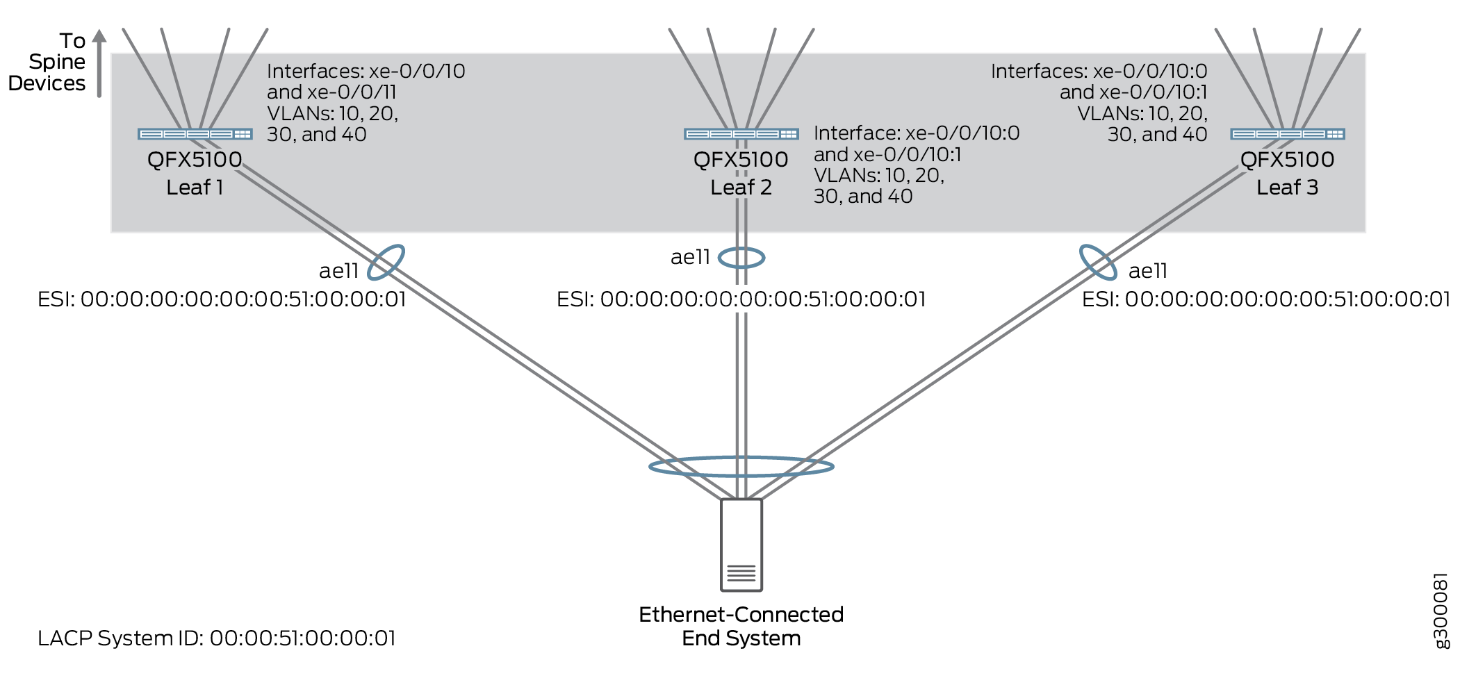
ESI Topology for Leaf 1, Leaf 2, and Leaf 3

    Leaf 1:

    If your configuration uses MAC-VRF instances, you must also add the configured aggregated Ethernet interface to the MAC-VRF instance:

  7. Configure VLANs and map them to VNIs. This step enables the VLANs to participate in VNIs across the EVPN/VXLAN domain.

    This step shows the VLAN to VNI mapping either in the default instance or in a MAC-VRF instance configuration.

    Leaf 1 (Default Instance):

    Leaf 1 (MAC-VRF Instance):

    The only difference with a MAC-VRF instance configuration is that you configure these statements in the MAC-VRF instance at the [edit routing-instances mac-vrf-instance-name] hierarchy level, as follows:

Verifying the Bridged Overlay on the Leaf Device

Run the following commands to verify that the overlay is working properly on your leaf devices.

The commands here show output for a default instance configuration. With a MAC-VRF instance configuration, you can alternatively use:

  • show mac-vrf forwarding commands that are aliases for the show ethernet-switching commands in this section.

  • The show mac-vrf routing instance command, which is an alias for the show evpn instance command in this section.

See MAC-VRF Routing Instance Type Overview for tables of show mac-vrf forwarding and show ethernet-switching command mappings, and show mac-vrf routing command aliases for show evpn commands.

The output with a MAC-VRF instance configuration displays similar information for MAC-VRF routing instances as this section shows for the default instance. One main difference you might see is in the output with MAC-VRF instances on devices where you enable the shared tunnels feature. With shared tunnels enabled, you see VTEP interfaces in the following format:

where:

  • index is the index associated with the MAC-VRF routing instance.

  • shared-tunnel-unit is the unit number associated with the shared tunnel remote VTEP logical interface.

For example, if a device has a MAC-VRF instance with index 26 and the instance connects to two remote VTEPs, the shared tunnel VTEP logical interfaces might look like this:

If your configuration uses an IPv6 Fabric, you provide IPv6 address parameters where applicable. Output from the commands that display IP addresses reflect the IPv6 device and interface addresses from the underlying fabric. See IPv6 Fabric Underlay and Overlay Network Design and Implementation with EBGP for the fabric parameters reflected in command outputs in this section with an IPv6 Fabric.

  1. Verify the interfaces are operational. Interfaces xe-0/0/10 and xe-0/0/11 are dual homed to the Ethernet-connected end system through interface ae11, while interfaces et-0/0/48 through et-0/0/51 are uplinks to the four spine devices.
  2. Verify that the leaf devices have reachability to their peer leaf devices.

    For example, on Leaf 1 with an IPv6 Fabric, view the possible routes to remote Leaf 2 using the show route address command with device IPv6 address 2001:db8::192:168:1:2 for Leaf 2.

  3. Verify on Leaf 1 and Leaf 3 that the Ethernet switching table has installed both the local MAC addresses and the remote MAC addresses learned through the overlay.
    Note:

    To identify end systems learned remotely from the EVPN overlay, look for the MAC address, ESI logical interface, and ESI number. For example, Leaf 1 learns about an end system with the MAC address of 02:0c:10:03:02:02 through esi.1885. This end system has an ESI number of 00:00:00:00:00:00:51:10:00:01. Consequently, this matches the ESI number configured for Leaf 4, 5, and 6 (QFX5110 switches), so we know that this end system is multihomed to these three leaf devices.

  4. Verify the remote EVPN routes from a specific VNI and MAC address.
    Note:

    The format of the EVPN routes is EVPN-route-type:route-distinguisher:vni:mac-address.

    For example, with an IPv4 Fabric, view the remote EVPN routes from VNI 1000 and MAC address 02:0c:10:01:02:02. In this case, the EVPN routes come from Leaf 4 (route distinguisher 192.168.1.4) by way of Spine 1 (192.168.0.1).

    Or with an IPv6 Fabric, for example, view the remote EVPN routes from VNI 1000 and MAC address c8:fe:6a:e4:2e:00. In this case, the EVPN routes come from Leaf 2 (route distinguisher 192.168.1.2) by way of Spine 1 (2001:db8::192:168:0:1).

  5. Verify the source and destination address of each VTEP interface and view their status. Use the show ethernet-switching vxlan-tunnel-end-point source and show interfaces vtep commands.
    Note:

    A scaled-out reference design can have 96 leaf devices, which corresponds to 96 VTEP interfaces - one VTEP interface per leaf device. The output here is truncated for readability.

    The following example shows these commands with an IPv4 Fabric:

    Or the following example shows these commands with an IPv6 Fabric:

  6. Verify that each VNI maps to the associated VXLAN tunnel.

    For example, with an IPv4 Fabric:

    Or for example, with an IPv6 Fabric:

  7. Verify that MAC addresses are learned through the VXLAN tunnels.

    For example, with an IPv4 Fabric:

    Or for example, with an IPv6 Fabric:

  8. Verify multihoming information of the gateway and the aggregated Ethernet interfaces.

    For example, with an IPv4 Fabric:

    Or for example, with an IPv6 Fabric:

  9. Verify that the VXLAN tunnel from one leaf to another leaf is load balanced with equal cost multipathing (ECMP) over the underlay.
  10. Verify that remote MAC addresses are reachable through ECMP.

    For example, with an IPv4 Fabric:

    Note:

    Though the MAC address is reachable over multiple VTEP interfaces, QFX5100, QFX5110, QFX5120-32C, and QFX5200 switches do not support ECMP across the overlay because of a merchant ASIC limitation. Only the QFX10000 line of switches contain a custom Juniper Networks ASIC that supports ECMP across both the overlay and the underlay.

    Or for example, with an IPv6 Fabric:

  11. Verify which device is the Designated Forwarder (DF) for broadcast, unknown, and multicast (BUM) traffic coming from the VTEP tunnel.

    For example, with an IPv4 Fabric:

    Note:

    Because the DF IP address is listed as 192.168.1.2, Leaf 2 is the DF.

    Or, for example, with an IPv4 Fabric:

    Note:

    Because the DF IPv6 address is listed as 2001:db8::192:168:1:1, Leaf 1 is the DF.

Bridged Overlay — Release History

Table 1 provides a history of all of the features in this section and their support within this reference design.

Table 1: Bridged Overlay in the Cloud Data Center Reference Design– Release History

Release

Description

19.1R2

QFX10002-60C and QFX5120-32C switches running Junos OS Release 19.1R2 and later releases in the same release train support all features documented in this section.

18.4R2

QFX5120-48Y switches running Junos OS Release 18.4R2 and later releases in the same release train support all features documented in this section.

18.1R3-S3

QFX5110 switches running Junos OS Release 18.1R3-S3 and later releases in the same release train support all features documented in this section.

17.3R3-S2

All devices in the reference design that support Junos OS Release 17.3R3-S2 and later releases in the same release train also support all features documented in this section.