Help us improve your experience.

Let us know what you think.

Do you have time for a two-minute survey?


Routed Overlay Design and Implementation

A third overlay option for this Cloud Data Center reference design is a routed overlay, as shown in Figure 1.

Figure 1: Routed OverlayRouted Overlay

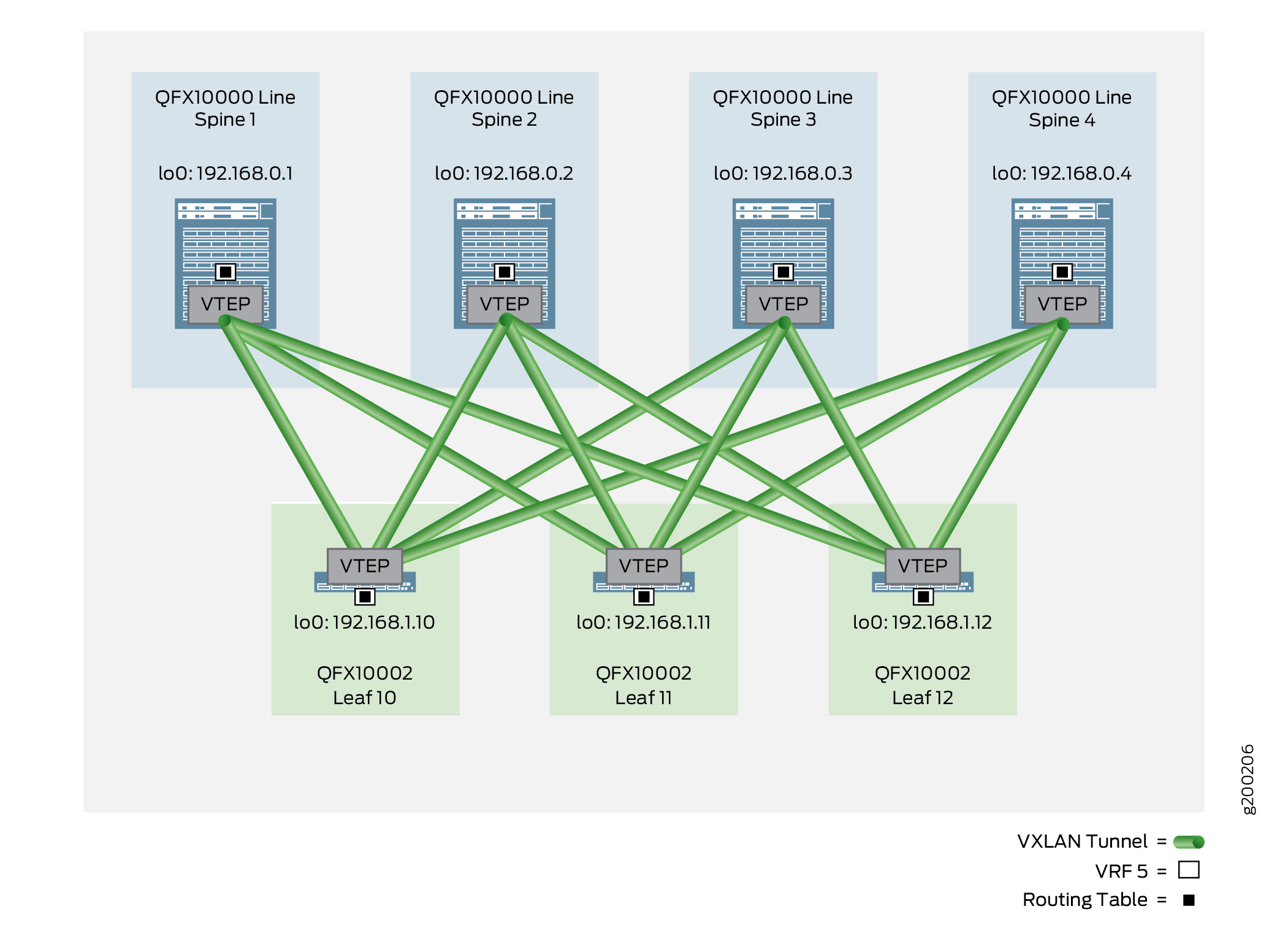
The routed overlay service supports IP-connected end systems that interconnect with leaf devices using IP (not Ethernet). The end systems can use dynamic routing protocols to exchange IP routing information with the leaf devices. The IP addresses and prefixes of the end systems are advertised as EVPN type-5 routes and imported by other EVPN/VXLAN-enabled spine and leaf devices into a corresponding VRF routing instance.

To implement a routed overlay, you must use one of the QFX10000 line of switches as the leaf devices. (The QFX5110 is planned to be verified in a future revision of this guide.)

On the spine devices, create a VRF routing instance to accept the EVPN type-5 routes. Include route distinguishers and route targets, use the advertise direct-nexthop option, and configure the same VNI used by the leaf devices.

To configure the leaf devices, create a policy that matches on the BGP routes received from the end systems, and send these routes into a VRF routing instance enabled for EVPN type-5 routes so they can be shared with other leaf and spine devices in the same IP VNI.

For an overview of routed overlays, see the Routed Overlay section in Data Center Fabric Blueprint Architecture Components.

The following sections show the detailed steps of how to configure and verify the routed overlay:

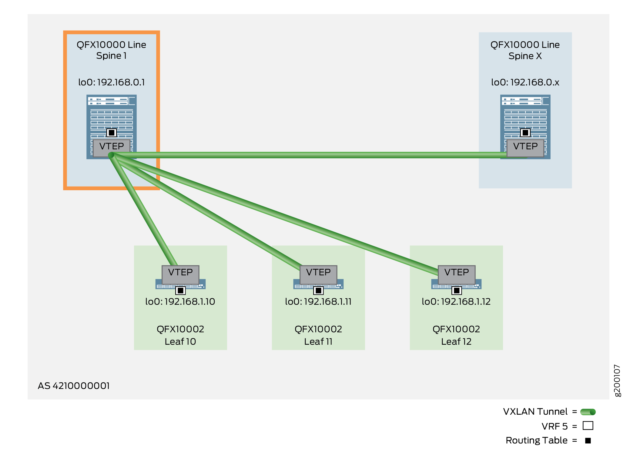
Configuring the Routed Overlay on a Spine Device

To configure the routed overlay on a spine device, perform the following:

Note:

The following example shows the configuration for Spine 1, as shown in Figure 2.

Figure 2: Routed Overlay – Spine DevicesRouted Overlay – Spine Devices
  1. Ensure the IP fabric underlay is in place. To see the steps required to configure an IP fabric on a spine device, see IP Fabric Underlay Network Design and Implementation.
  2. Confirm that your IBGP overlay is up and running. To configure an IBGP overlay on your spine device, see Configure IBGP for the Overlay.
  3. Create a VRF routing instance that enables the EVPN type-5 option (also known as IP prefix routes). Configure a route distinguisher and route target, provide load balancing for EVPN type-5 routes with the multipath ECMP option, enable EVPN to advertise direct next hops, specify VXLAN encapsulation, and assign the VNI.
    Note:

    This VRF can be used for north-south traffic flow and will be explained in a future version of this guide.

    Spine 1:

Verifying the Routed Overlay on a Spine Device

To verify that the routed overlay on a spine device is working, perform the following:

  1. Verify that the EVPN type-5 routes are being advertised and received for IPv4 and IPv6.

    EVPN to IPv4 Imported Prefixes

  2. Verify that the end system is multihomed to all three QFX10000 leaf devices for both IPv4 and IPv6.

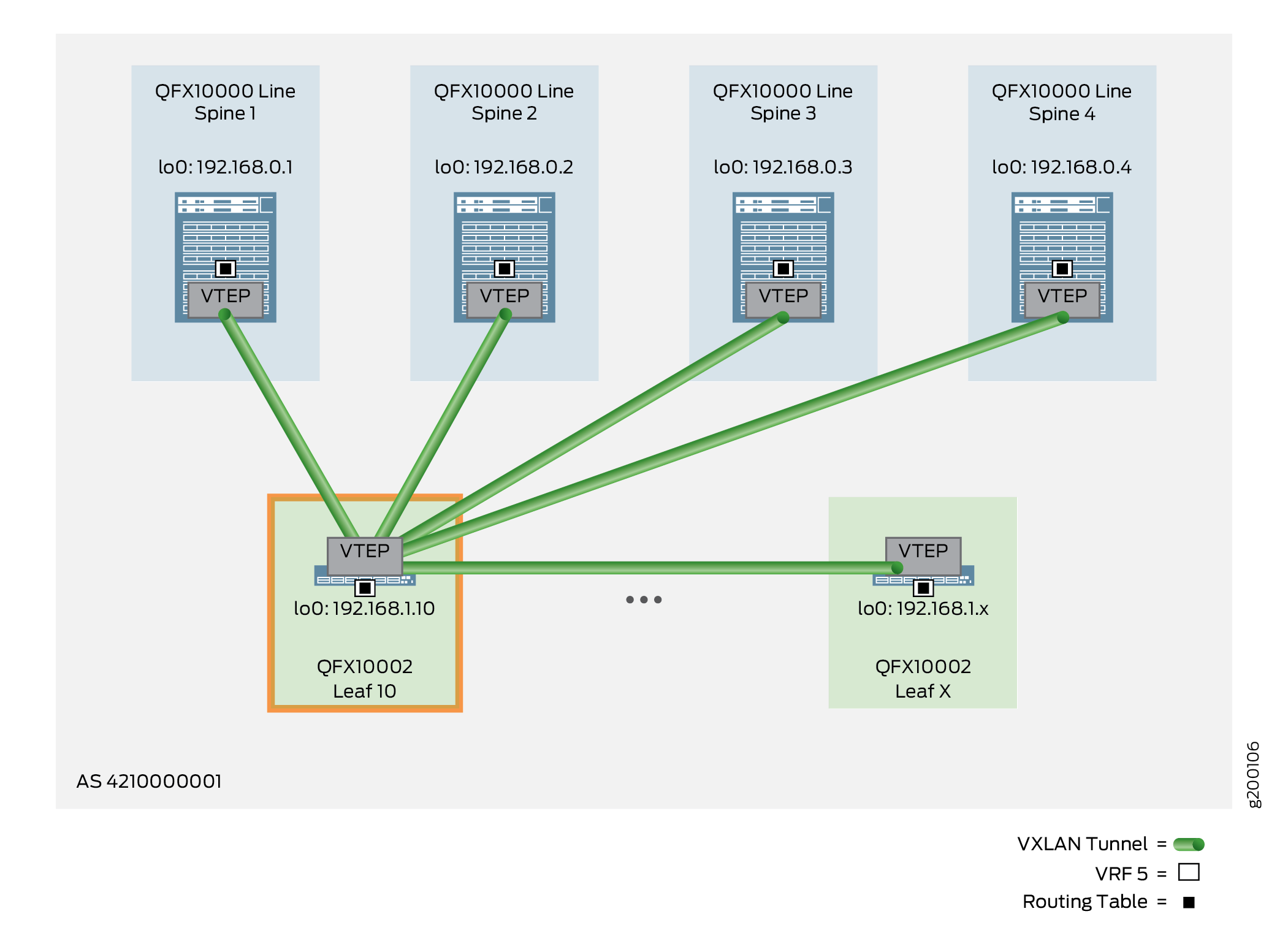
Configuring the Routed Overlay on a Leaf Device

To configure the routed overlay on a leaf device, perform the following:

Note:

The following example shows the configuration for Leaf 10, as shown in Figure 3.

Figure 3: Routed Overlay – Leaf DevicesRouted Overlay – Leaf Devices
  1. Ensure the IP fabric underlay is in place. To see the steps required to configure an IP fabric on a leaf device, see IP Fabric Underlay Network Design and Implementation.
  2. Confirm that your IBGP overlay is up and running. To configure an IBGP overlay on your leaf device, see Configure IBGP for the Overlay.
  3. Configure a VRF routing instance to extend EBGP peering to an end system. Specify a route target, route distinguisher, and the IP address and ASN (AS 4220000001) of the IP-connected end system to allow the leaf device and end system to become BGP neighbors. To learn how to implement IP multihoming, see Multihoming an IP-Connected End System Design and Implementation.
    Note:

    Each VRF routing instance in the network should have a unique route distinguisher. In this reference design, the route distinguisher is a combination of the loopback interface IP address of the device combined with a unique identifier to signify the device. For VRF 5, the loopback interface IP address on Leaf 10 is 192.168.1.10 and the ID is 15, making the route distinguisher 192.168.1.10:15.

    Leaf 10:

  4. Create a policy to match direct routes and BGP routes.

    Leaf 10:

  5. Complete your configuration of the VRF routing instance by configuring the EVPN type-5 option. To implement this feature, configure EVPN to advertise direct next hops such as the IP-connected end system, specify VXLAN encapsulation, assign the VNI, and export the BGP policy that accepts the end system routes.

    Leaf 10:

Verifying the Routed Overlay on a Leaf Device

Note:

The operational mode command output included in the following sections assumes you have configured IP multihoming as explained in Multihoming an IP-Connected End System Design and Implementation.

To verify that the routed overlay on a leaf device is working, perform the following:

  1. Verify that the IPv4 routes from the VRF are converted to EVPN type-5 routes are advertised to EVPN peers.

    IPv4 to EVPN Exported Prefixes

    IPv6 to EVPN Exported Prefixes

    EVPN to IPv6 Imported Prefixes

  2. View the VRF route table for IPv4, IPv6, and EVPN to verify that the end system routes and spine device routes are being exchanged.

    This is the IPv4 section

    This is the IPv6 section

    This is the EVPN section. EVPN routes use the following convention:

    Type:Route Distinguisher::0::IP Address::Prefix/NLRI Prefix

Routed Overlay — Release History

Table 1 provides a history of all of the features in this section and their support within this reference design.

Table 1: Routed Overlay in the Cloud Data Center Reference Design – Release History

Release

Description

19.1R2

QFX10002-60C and QFX5120-32C switches running Junos OS Release 19.1R2 and later releases in the same release train support all features documented in this section.

18.4R2

QFX5120-48Y switches running Junos OS Release 18.4R2 and later releases in the same release train support all features documented in this section.

18.1R3-S3

QFX5110 switches running Junos OS Release 18.1R3-S3 and later releases in the same release train support all features documented in this section.

17.3R3-S1

All devices in the reference design that support Junos OS Release 17.3R3-S1 and later releases in the same release train also support all features documented in this section.