Upgrading the PTX5000 FPCs
Preparing to Upgrade the FPCs in a PTX5000
When you upgrade a PTX5000 to use second-generation or third-generation FPCs, the forwarding capacity increases. See FPCs Supported on the PTX5000 for more information about the forwarding capacity for each type of FPC.
To prepare to upgrade the FPCs in a PTX5000:
Ensure the site still meets the requirements—such as weight and power—when using the new components. See Overview of Preparing the Site for the PTX5000
Determine the model numbers of the following components already installed:
SIBs
FPCs
Power distribution units (PDUs)
Power supply modules (PSMs)
Ensure you have the required new components.
Up to eight FPCs
Nine SIBs
PDUs
PSMs
Fan trays
Note:For the specific hardware requirements for each type of FPC, see PTX5000 FPC Upgrade Kit.
Review all safety guidelines and warnings for the PTX5000.
Warning:To avoid harm to yourself or the router as you install and maintain it, you must follow the safety procedures for working with Internet routers, as well as the guidelines and warnings for working with and near electrical equipment. However, providing an exhaustive set of guidelines for working with electrical equipment is beyond the scope of this documentation.
Upgrade the software on the PTX5000.
To accommodate the change in the addressing scheme with eight Packet Forwarding Engines in the new FPC, you must upgrade the Junos OS on the PTX5000 to Junos OS Release 14.1. The upgrade to Junos OS Release 14.1 requires a reboot of the PTX5000.
PTX5000 FPC Upgrade Kit
The following components are required to upgrade the FPCs to FPC2-PTX-P1A in a PTX5000:
FPC2-PTX-P1A FPCs
SIB2-I-PTX5K SIBs
PDU2-PTX-DC power distribution unit
PSM2-PTX-DC power supply module
Note:PTX5K-PSM2TRAY is used only if you are upgrading the power supplies to high capacity PDUs and PSMs.
Note:To install all eight FPC2-PTX-P1A FPCs, you must upgrade the PDUs and PSMs with PDU2-PTX-DC and PSM2-PTX-DC, respectively. Otherwise, you can only install a maximum of six FPC2-PTX-P1A FPCs. Refer to Calculating PTX5000 Power Consumption for more details.
The following components are required to upgrade the FPCs to FPC3-PTX-U2 in a PTX5000:
FPC3-PTX-U2 FPCs
SIB3-PTX5K SIBs
FAN3-PTX-H fan tray
Note:When upgrading to FPC3-PTX-U2 FPCs, you are not required to upgrade to the PDU2-PTX-DC power distribution unit or the PSM2-PTX-DC power supply module.
The following components are required to upgrade the FPCs to FPC3-PTX-U3 in a PTX5000:
FPC3-PTX-U3 FPCs
SIB3-PTX5K SIBs
FAN3-PTX-H fan tray
PDU2-PTX-DC power distribution unit
PSM2-PTX-DC power supply module
Note:PTX5K-PSM2TRAY is used only if you are upgrading the power supplies to high capacity PDUs and PSMs.
Note:The PTX5000 supports two midplanes. The FPC3-PTX-U3 FPC must be installed in the PTX5000BASE2 model midplane.
Upgrading the FPCs in an Operational PTX5000
This topic describes the steps you take to upgrade your operational PTX5000 with new FPCs.
This topic does not describe the steps required to update an offline router with FPCs. See Upgrading the FPCs in an Offline PTX5000 for more information.
When upgrading to third-generation FPCs (see FPCs Supported on the PTX5000), be aware of the following:
When you are upgrading the FPCs on an operational PTX5000, make sure that the router is running Junos OS Release 15.1F5.
If the PTX5000 is running Junos OS Release 15.1F3 or 15.1F4, you must use the offline upgrade procedure. See Upgrading the FPCs in an Offline PTX5000.
Before you begin to upgrade:
Ensure that you understand how to prevent electrostatic discharge (ESD) damage.
Unpack the upgrade components and verify the parts received.
Gather the following tools required for the upgrade and integration:
Antistatic mat or antistatic bag for any components you remove from the chassis
Dust-free resealable plastic bags for temporary storage of port dust covers
ESD grounding wrist strap
Phillips (+) screwdriver, number 2
To avoid harm to yourself or the PTX5000 as you install and maintain it, you must follow the safety procedures for working with Internet routers, as well as the guidelines and warnings for working with and near electrical equipment. However, providing an exhaustive set of guidelines for working with electrical equipment is beyond the scope of this documentation.
See General Safety Guidelines and Warnings.
To upgrade your operational PTX5000 with new FPCs follow these procedures:
- Upgrading Junos OS on an Operational PTX5000
- Upgrading to the High Capacity Power System
- Upgrading the Horizontal Fan Tray
- Removing and Replacing SIBs in an Operational PTX5000
- Upgrading the FPCs in an Operational PTX5000
Upgrading Junos OS on an Operational PTX5000
Upgrade Junos OS on the PTX5000 to the appropriate Junos OS Release for the FPC being upgraded to (see FPCs Supported on the PTX5000). For Junos OS upgrade information, see the Installation and Upgrade Guide.
Upgrading to the High Capacity Power System
The FPC that you are upgrading to might require you to upgrade your PTX5000 with the High Capacity power system. To determine whether an upgrade to the High Capacity power system is required, see PTX5000 FPC Upgrade Kit. To upgrade the power supply system, see Upgrading to the High Capacity DC Power System and Upgrading to the High Capacity AC Power System.
Upgrading the Horizontal Fan Tray
The FPC that you are upgrading to might require an upgraded horizontal fan tray. To determine wether an upgrade to the horizontal fan tray is required, see PTX5000 FPC Upgrade Kit. To upgrade the horizontal fan tray, see Replacing a PTX5000 Horizontal Fan Tray.
Removing and Replacing SIBs in an Operational PTX5000
To remove a SIB:
- Remove the offline SIB:
- Grasp both ejector handles, pull firmly, and slide the
SIB about three-quarters of the way out of the chassis.Figure 1: Removing a SIB from the PTX5000
- Grasp both ejector handles, pull firmly, and slide the
SIB about three-quarters of the way out of the chassis.
- Install the new SIB:Figure 2: Installing a SIB into the PTX5000
- Attach an ESD grounding strap to your bare wrist, and connect the strap to one of the ESD points on the chassis.
- Place one hand underneath the SIB to support it. With the other hand, hold one of the ejector handles on the SIB faceplate.
- Carefully align the sides of the SIB with the guides inside the chassis.
- Slide the SIB into the chassis, carefully ensuring that it is correctly aligned.
- Twist the ejector handles clockwise until they stop.
Upgrading the FPCs in an Operational PTX5000
Before you begin upgrading the FPCs, use the show chassis hardware command to verify the following:
That the correct SIBs are installed.
That the correct PDUs and PSMs are installed.
That the correct fan trays are installed.
To determine which hardware is required for the FPC that you are upgrading to, see PTX5000 FPC Upgrade Kit.
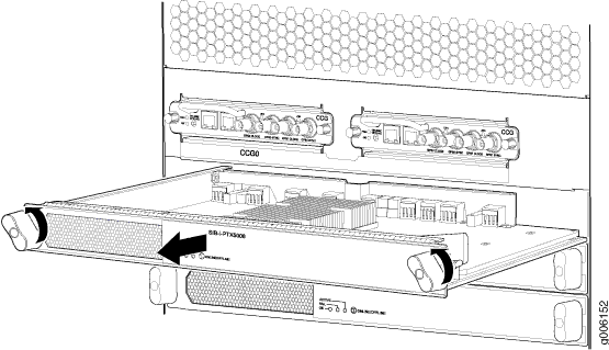
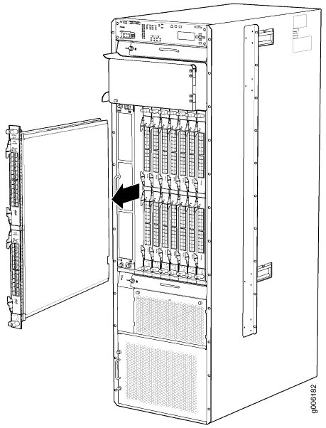
To remove an existing FPC:
- Grasp the handles and slide the FPC straight out of the
card cage halfway.Figure 3: Removing an FPC from the PTX5000
To install an FPC:
The FPC power connector is located in the corner where the bottom and the connector edges meet. If a power connector prong becomes bent, it no longer aligns with the socket connector on the midplane, and the FPC no longer functions.
Attach an ESD grounding strap to your bare wrist, and connect the strap to one of the ESD points on the chassis.
Place the FPC on an antistatic mat.
Take each PIC to be installed in the replacement FPC out of its electrostatic bag and identify the slot on the FPC where it will be installed.
Verify that each fiber-optic transceiver has a rubber safety cap covering the transceiver. If it does not, cover the transceiver with a safety cap.
Install each PIC into the appropriate slot on the FPC. See PTX Series PIC/FPC Compatibility for installing the supported PICs on the FPC. For information about installing a PIC, see the installation instructions in Replacing a PTX5000 PIC.
Locate the slot in the FPC card cage in which you plan to install the FPC.
Inspect the slot in the FPC card cage to verify that there are no missing or bent pins on the midplane.
Inspect the FPC to verify that the connectors are not misaligned or damaged.
Orient the FPC vertically with the component side facing to the right. Be sure the FPC is right-side up, with the components on the right of the FPC.
CAUTION:When the FPC is out of the chassis, do not hold it by the ejector handles, bus bars, or edge connectors. These components cannot support its weight.
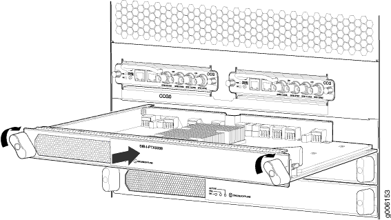
Carefully align the connector edge of the FPC with the appropriate empty slot in the chassis.
Lift the FPC into place and carefully align the bottom and top of the FPC with the guides inside the card cage.
Figure 4: Installing an FPC into the PTX5000
Gently rest the bottom edge of the FPC on the bottom edge of the slot opening, making contact a short distance forward of the power connector.
CAUTION:Take care not to bend or otherwise damage the power connector prongs.
Slowly slide the FPC into the slot until you feel resistance.
Align the ejector handles on the FPC faceplate in a position close to horizontal.
Simultaneously turn both ejector handles clockwise until you cannot turn them further.
Remove the rubber safety cap from each fiber-optic transceiver and fiber-optic cable.
Laser Warning:Do not look directly into a fiber-optic transceiver or into the ends of fiber-optic cables. Fiber-optic transceivers and fiber-optic cable connected to a transceiver emit laser light that can damage your eyes.
Insert the appropriate cable into the cable connector ports on each PIC on the FPC. Secure the cables so that they are not supporting their own weight. Place excess cable out of the way in a neatly coiled loop, using the cable management system. Placing fasteners on a loop helps to maintain its shape.
CAUTION:Do not let fiber-optic cable hang free from the connector. Do not allow fastened loops of cable to dangle, which stresses the cable at the fastening point.
CAUTION:Avoid bending fiber-optic cable beyond its minimum bend radius. An arc smaller than a few inches in diameter can damage the cable and cause problems that are difficult to diagnose.
Use one of the following methods to bring the FPC online:
Press and hold the FPC ONLINE/OFFLINE button until the green OK LED next to the button begins to blink, in about 5 seconds.
Issue the following CLI command:
user@host> request chassis fpc slot slot-number online
CAUTION:After the OK LED lights steadily, wait at least 30 seconds before removing the FPC again, removing an FPC from a different slot, or inserting an FPC in a different slot.
Verify that all the eight FPCs are installed properly and working by using the
show chassis fpccommand. The replaced FPCs are displayed asFPC Ein the command output.
You can also verify correct FPC and PIC functioning by issuing
the show chassis fpc and show chassis fpc
pic-status commands, as described in Maintaining
the PTX5000 FPCs.
Upgrading the FPCs in an Offline PTX5000
This topic describes the steps you take to upgrade your offline PTX5000 with new FPCs.
This topic does not describe the steps required to update an operational router with new FPCs. See Upgrading the FPCs in an Operational PTX5000 for more information.
Before you begin to upgrade:
Perform the tasks described inPreparing to Upgrade the FPCs in a PTX5000 .
Ensure that you understand how to prevent ESD damage.
Unpack the upgrade components and verify the parts received.
Gather the tools required for the upgrade and integration.
Antistatic mat or antistatic bag for any components you remove from the chassis
Dust-free resealable plastic bags for temporary storage of port dust covers
ESD grounding wrist strap
Phillips (+) screwdriver, number 2
To avoid harm to yourself or the PTX5000 as you install and maintain it, you must follow the safety procedures for working with Internet routers, as well as the guidelines and warnings for working with and near electrical equipment. However, providing an exhaustive set of guidelines for working with electrical equipment is beyond the scope of this documentation.
See General Safety Guidelines and Warnings.
To upgrade your offline PTX5000 with new FPCs:
- Upgrading Junos OS on an Offline PTX5000
- Powering Off the PTX5000 During FPC Upgrade
- Removing and Replacing SIBs in a PTX5000
- Powering On the PTX5000
- Verifying the Replaced SIBs
- Upgrading the FPCs
Upgrading Junos OS on an Offline PTX5000
Upgrade Junos OS on the PTX5000 to the appropriate Junos OS Release for the FPC being upgraded to (see FPCs Supported on the PTX5000). See the Installation and Upgrade Guide.
Powering Off the PTX5000 During FPC Upgrade
To power off the PTX5000, follow these steps:
Removing and Replacing SIBs in a PTX5000
To remove a SIB:
- Grasp both ejector handles, pull firmly, and slide the
SIB about three-quarters of the way out of the chassis.Figure 5: Removing a SIB
To install the new SIBs:
Attach an ESD grounding strap to your bare wrist, and connect the strap to one of the ESD points on the chassis.
Press and hold the ONLINE/OFFLINE button on the SIB faceplate. The green OK LED on the faceplate turns off. Hold the button down until the LED completely turns off.
Place one hand underneath the SIB to support it. With the other hand, hold one of the ejector handles on the SIB faceplate.
Carefully align the sides of the SIB with the guides inside the chassis.
Slide the SIB into the chassis, carefully ensuring that it is correctly aligned.
Twist the ejector handles clockwise until they stop.
Install all the SIBs one by one.
Powering On the PTX5000
Verifying the Replaced SIBs
Upgrading the FPCs
Before you begin upgrading the FPCs, use the show chassis hardware command to verify the following:
That the correct SIBs are installed.
That the correct PDU and PSM are installed.
That the correct fan tray is installed.
To determine which hardware is required for the FPC that you are upgrading to, see PTX5000 FPC Upgrade Kit.
To upgrade the FPCs:
- Verify that all the SIBs on the PTX5000 are correct, by
using the
show chassis hardwarecommand. - Replace the FPCs on the PTX5000 with the new FPCs. Follow the replacement procedure in Replacing a PTX5000 FPC.
- Verify that all eight FPCs are installed properly and
working by using the
show chassis fpccommand.