PTX10008 System Overview
PTX10008 Hardware Overview
The Juniper Networks PTX10008 Packet Transport Router helps network operators achieve their business goals while effectively handling current and future traffic demands. For more information, read the following topics:
- System Overview
- Benefits of the PTX10008 Router
- Chassis Description
- Switch Fabric
- Routing and Control Board
- Line Cards
- Cooling System
- Power Supplies
- Software
System Overview
The Juniper Networks PTX10008 Packet Transport Router enables cloud and data center operators to smoothly transition from 10-Gigabit and 40-Gigabit Ethernet networks to 100-Gigabit, 400-Gigabit, and 800 Gigabit Ethernet high-performance networks. This flexible, 13 rack unit (13-U) modular chassis has eight line card slots.
The switch fabric consists of six Switch Interface Boards (SIBs). There are two models of SIBs that correspond to the two types of switch fabric that support two different types of line cards. The JNP10008-SF SIB supports five standard line cards and operates in standard Junos OS. PTX10008 routers with JNP10008-SF switch fabric has a forwarding capacity of 42 Tbps. The JNP10008-SF3 SIB and JNP10008-SF5 SIB support PTX10K-LC1201-36CD, PTX10K-LC1202-36MR, and PTX10K-LC1301-36DD line cards and operate in Junos OS Evolved systems. PTX10008 routers with JNP10008-SF3 switch fabric has a forwarding capacity of 115 Tbps. PTX10008 routers with JNP10008-SF5 switch fabric has a forwarding capacity of 230.4 Tbps.
The PTX10008 (IP core) router is available in both base and redundant configurations for both AC and DC operation. All systems feature front-to-back airflow.
You can manage and monitor PTX10008 router by using the CLI. In addition to the CLI, you can manage and monitor the PTX10008 router by using Juniper Routing Director (formerly Juniper Paragon Automation) or Juniper Paragon Automation.
Benefits of the PTX10008 Router
-
System capacity—The PTX10008 Packet Transport Router has a 13-U form factor and supports 115.2 Tbps per chassis.
-
Full-scale IP and MPLS routing—PTX10008 software scales to thousands of BGP peers, tens of millions of routes in the routing tables,and supports high forwarding table scale suitable for internet peering deployments.
-
Source Packet Routing in Networking (SPRING)—SPRING on PTX10008 supports the latest SPRING innovations such as path provisioning via BGP SR-TE, and PCED protocols. It also supports many more features such as Topology independent loop free alternates (TI-LFA) and Operation, Administration, and Maintenance (OAM).
-
Always-on infrastructure base—The PTX10008 is engineered with full hardware redundancy for cooling, power, switch fabric, and control plane.
-
Nondisruptive software upgrades—The Junos operating system (Junos OS) on the PTX10008 supports high availability (HA) features such as graceful Routing Engine switchover (GRES), and nonstop active routing (NSR), providing software upgrades and changes without disrupting network traffic.
Chassis Description
The PTX10008 router is 13 U tall. Up to three PTX10008 routers can fit in a standard 42-U rack with adequate cooling and power. All key PTX10008 router components are field-replaceable units (FRUs). Figure 1 illustrates the key components visible from the front of the chassis, Figure 2 illustrates the components that are visible from the rear of the chassis, and Figure 3 illustrates the components that are internal to the chassis.
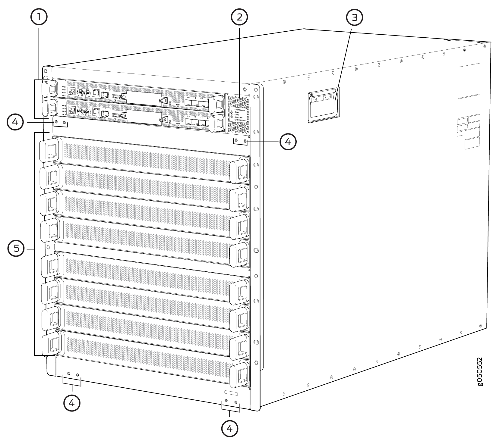
1 — Routing and Control Boards | 4 — Installation holes for the front panel |
2 — Status panel | 5 — Line card slots 0–7 (numbered top to bottom) |
3 — Handle |
Some chassis ship with an enhanced power bus to future-proof the chassis beyond the current generation of line cards. If you are using any of the line cards compatible with JNP10008-SF3 or JNP10008-SF5, the standard chassis is sufficient for your operation. You can determine the chassis you have by markings on the status panel (see PTX10008 Status Panel).
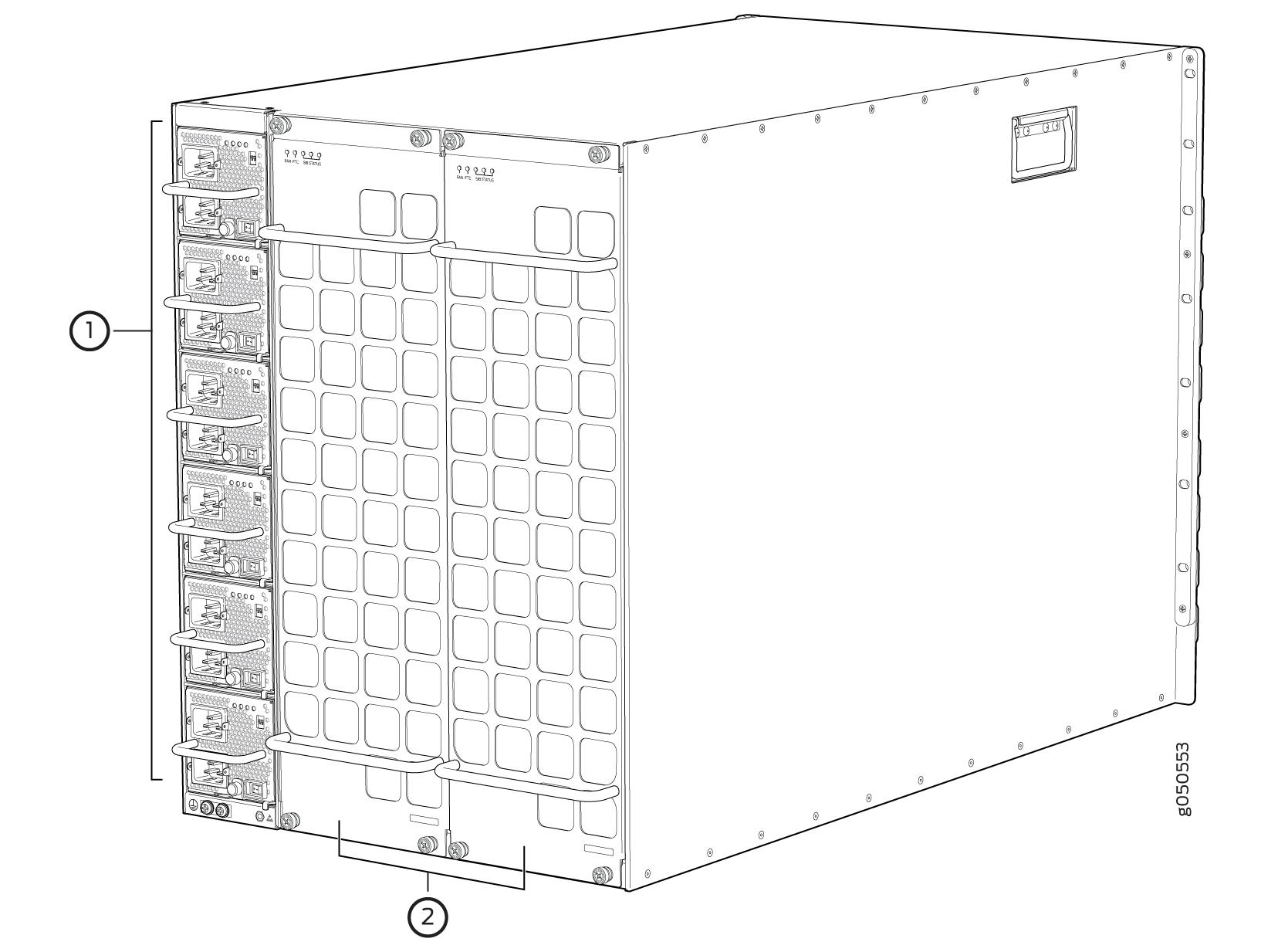
1 — AC or DC power supplies numbered 0–5 (top to bottom) | 2 — Fan trays with redundant fans |
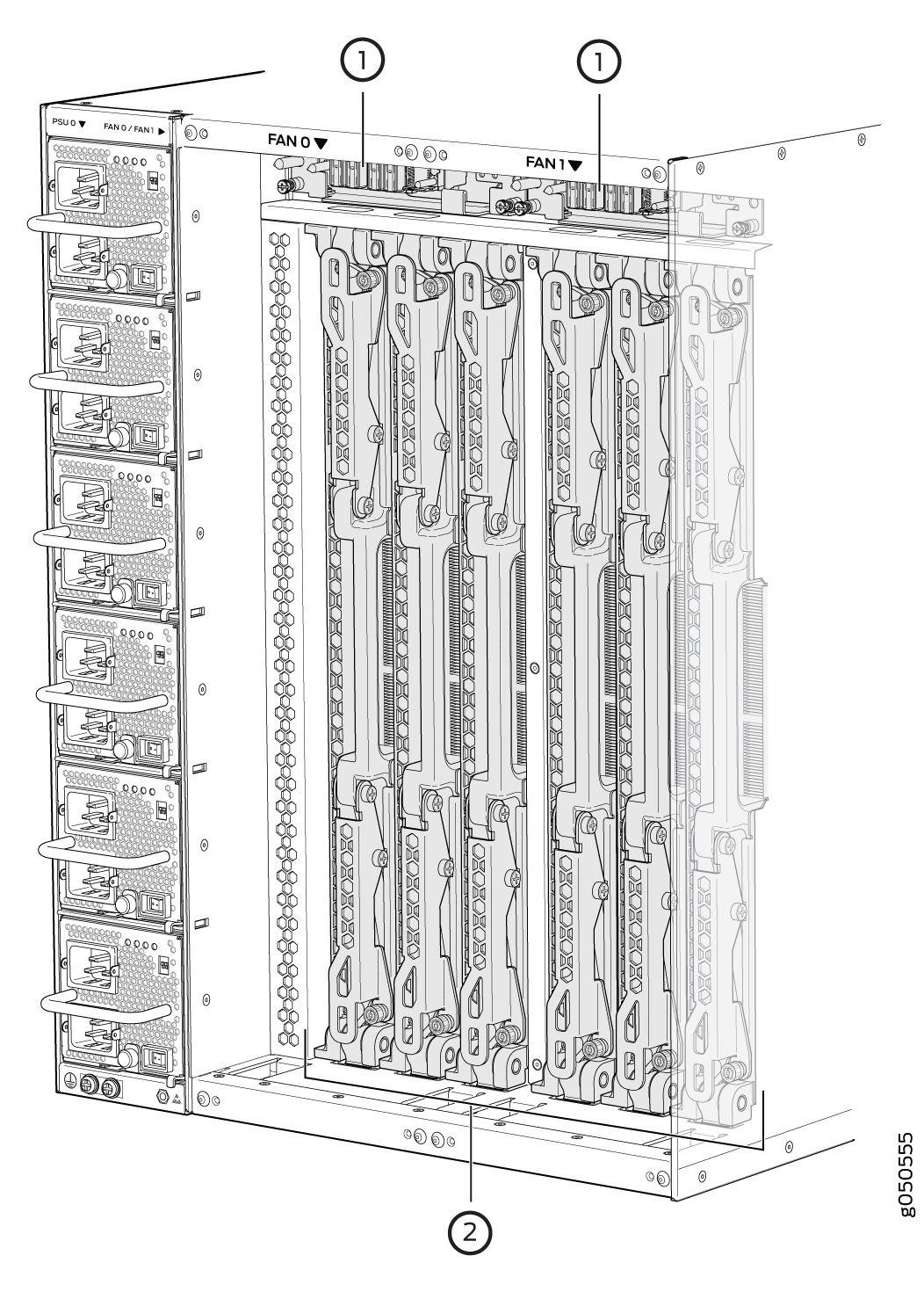
1 — Fan tray controllers | 2 — Switch fabric |
See PTX10008 Chassis Physical Specifications and PTX10008 Field-Replaceable Units.
Switch Fabric
Switch Interface Boards (SIBs) create the switch fabric for the PTX10008. There are three SIB models: JNP10008-SF, JNP10008-SF3, and JNP10008-SF5. Each SIB model has a set of unique connectors to mate the line cards and the RCB to the switch fabric. Some system components are also designed to operate with a specific switch fabric. See Table 1 for the components that each switch fabric supports.
For the JNP10008-SF switch fabric, five SIBs provide the necessary switching functionality to a PTX10008 router. Up to six SIBs can be installed to provide n+1 redundancy. For the JNP10008-SF3 and JNP10008-SF5 switch fabrics, there are three supported configurations that range from three to six SIBs. In all the switch fabric configurations, SIBs are installed between the line cards and the fan trays inside the chassis. Each PTX10008 SIB has eight connectors that match to a line-card slot, eliminating the need for a backplane. See PTX10008 Switch Interface Board Description.
Each switch fabric has designated components.
|
Component |
JNP10008-SF |
JNP10008-SF3 |
JNP10008-SF5 |
|---|---|---|---|
|
Operating system |
Junos OS Release 15.1X53-D30 and later |
Junos OS Evolved Release 19.4R1-S1 and later |
Junos OS Evolved Release 24.4R2 and later |
|
RCB |
|
|
|
|
Fan tray and fan tray controller |
JNP10008-FAN with JNP10008-FAN-CTRL or JNP10008-FAN2 with JNP10008-FAN-FTC2 or JNP10008-FAN3 with JNP10008-FAN-FTC3 |
JNP10008-FAN2 with JNP10008-FAN-FTC2 or JNP10008-FAN3 with JNP10008-FAN-FTC3 |
JNP10008-FAN2 with JNP10008-FAN-FTC2 or JNP10008-FAN3 with JNP10008-FAN-FTC3 |
|
Power supply |
|
|
|
|
Line cards |
|
|
|
Routing and Control Board
The Routing and Control Board (RCB) contains a Routing Engine and is responsible for system management and system control in the PTX10008. See PTX10008 Routing and Control Board Components and Descriptions. RCBs are FRUs that are installed in the front of the chassis in the slots labeled CB0 and CB1. The base configuration has a single RCB. The fully redundant configuration has two RCBs. The RCB also contains Precision Time Protocol (PTP) ports and four Media Access Control Security (MACsec) capable ports. See PTX10008 Configurations and Upgrade Options.
The supported models of RCB for JNP10008-SF fabric systems are:
-
JNP10K-RE0
-
JNP10K-RE1
-
JNP10K-RE1-LT
-
JNP10K-RE1-128
The supported models of RCB for For JNP10008-SF3 fabric systems are:
-
JNP10K-RE1-E
-
JNP10K-RE1-ELT (Junos OS Evolved Release 20.3R1 and later)
-
JNP10K-RE1-E128
-
JNP10K-RE2-E128 (Junos OS Evolved Release 22.4R1 and later)
The RCB comes with Trusted Platform Module (TPM) 2.0 chip that supports DevID.
DevID is an X.509 cryptographic certificate. It is programmed into the TPM 2.0 chip during manufacturing and contains the serial number of the device.
-
JNP10K-RE3-E
-
JNP10K-RE3-E-LT
The supported models of RCB for For JNP10008-SF5 fabric systems are:
-
JNP10K-RE1-E
-
JNP10K-RE1-ELT
-
JNP10K-RE1-E128
-
JNP10K-RE2-E
-
JNP10K-RE2-E128
The RCB comes with Trusted Platform Module (TPM) 2.0 chip that supports DevID.
DevID is an X.509 cryptographic certificate. It is programmed into the TPM 2.0 chip during manufacturing and contains the serial number of the device.
-
JNP10K-RE3-E
-
JNP10K-RE3-E-LT
Line Cards
The PTX10008 has eight horizontal line card slots. The line cards combine a Packet Forwarding Engine and Ethernet interfaces enclosed in a single assembly. PTX10008 line card-architecture is based on a number of identical, independent Packet Forwarding Engine slices. Line cards are FRUs that can be installed in the line-card slots labeled 0 through 7 (top to bottom) on the front of the chassis. All line cards are hot-removable and hot-insertable. After the hot insertion, you need to bring the card online.
There are three types of line cards for the PTX10008: those line cards that are compatible with the JNP10008-SF switch fabric, those that are compatible with the JNP10008-SF3 switch fabric, and those that are compatible with the JNP10008-SF5 switch fabric. The line cards that operate with the JNP10008-SF switch fabric are:
-
PTX10K-LC1101, a 30-port 100-Gigabit or 40-Gigabit Ethernet quad small form-factor 28 (QSFP28) line card. By default, the interfaces are created with 100-Gbps port speed. Using the CLI, you can set the speed to 40-Gbps that can be used as either a native 40-gigabit interface or four independent 10-gigabit interfaces using a breakout cable. With breakout cables, the line card supports a maximum of 96 logical 10-Gigabit Ethernet interfaces.
-
PTX10K-LC1102, a 36-port 40-Gigabit Ethernet line card that supports quad small form-factor plus (QSFP+) transceivers. Twelve out of the 36 ports on this line card also support the 100-Gigabit Ethernet QSFP28 transceivers. You can configure each of the QSFP+ ports as either a native 40-Gigabit Ethernet interface or channelize the port as four 10-Gigabit Ethernet interfaces by using a breakout cable. When the 40 Gigabit Ethernet port is channelized, the line card supports a maximum of 144 logical 10-Gigabit Ethernet ports.
-
PTX10K-LC1104, a 6-port coherent dense wavelength-division multiplexing (DWDM) line card with Media Access Control Security (MACsec). The line card features built-in optics that support flexible rate modulation at 100-Gbps, 150-Gbps, and 200-Gbps speeds.
-
PTX10K-LC1105, a 30-port flexible configuration line card that supports QSFP+, QSFP28, QSFP28-DD, QSFP56, and QSFP-DD transceivers. You can configure either as 100-Gigabit Ethernet interfaces or as40-Gigabit Ethernet interfaces. The PTX10K-LC1105 line card supports MACsec security features.
-
QFX10000-60S-6Q, a 66-port multiple speed line card that provides 60 small form-factor pluggable plus (SFP+) ports that support 10-Gbps or 1-Gbps port speeds. The line card also has 2 dual-speed QSFP28 ports that support either 40-Gbps or 100-Gbps port speed, and 4 QSFP+ ports that support 40-Gbps speed.
The line cards that operate with the JNP10008-SF3 switch fabric are:
-
PTX10K-LC1201-36CD, a 36-port multiple speed line card that can be configured as 400-Gigabit, 200-Gigabit, 100-Gigabit, 50-Gigabit, 25-Gigabit, or 10-Gigabit Ethernet ports.
-
PTX10K-LC1202-36MR, a 36-port line card that has thirty-two QSFP28 ports capable of supporting 100-Gbps speed, and four QSFP56-DD ports capable of supporting 400-Gbps speed.
-
PTX10KLC1301-36DD, a line card that has 36-ports and offers a line rate throughput of 28.8 Tbps. The 36 high-density 800-Gigabit Ethernet (800GbE) QSFP-DD ports support speeds of up to 800 Gbps.
The maximum throughput that the line card offers in PTX10008 routers with JNP10008-SF3 installed is 12.8 Tbps.
The line cards that operate with the JNP10008-SF5 switch fabric are:
-
PTX10K-LC1201-36CD, a 36-port multiple speed line card that can be configured as 400-Gigabit, 200-Gigabit, 100-Gigabit, 50-Gigabit, 25-Gigabit, or 10-Gigabit Ethernet ports.
-
PTX10K-LC1202-36MR, a 36-port line card that has thirty-two QSFP28 ports capable of supporting 100-Gbps speed, and four QSFP56-DD ports capable of supporting 400-Gbps speed.
-
PTX10KLC1301-36DD, a line card that has 36-ports and offers a line rate throughput of 28.8 Tbps. The 36 high-density 800-Gigabit Ethernet (800GbE) QSFP-DD ports support speeds of up to 800 Gbps.
Cooling System
The cooling system in a PTX10008 router consists of:
1 — AC or DC power supplies numbered 0–5 (top to bottom) | 2 — Fan trays with redundant fans |
1 — Fan tray controllers | 2 — Switch fabric |
The JNP10008-FAN3 fan tray uses powerful fans offering higher airflow within the system, while also supporting higher operating temperature so as not to affect the reliability of the fans.
The JNP10008-FAN fan tray contains an array of 11 fans. The JNP10008-FAN2 and JNP10008-FAN3 fan tray contains an array of 22 fans. These fan arrays operate as a single hot-removable and hot-insertable field-replaceable unit. The fan trays install vertically on the rear of the chassis and provide front-to-back chassis cooling. For model differences, see PTX10008 Cooling System and Airflow.
For each model of fan tray, there is a corresponding model of fan tray controller.
Power Supplies
PTX10008 routers support AC, DC, high-voltage alternating current (HVAC) and high-voltage direct current (HVDC), by offering the following power supplies:
-
JNP10K-PWR-AC
-
JNP10K-PWR-AC2
-
JNP10K-PWR-AC3
-
JNP10K–PWR-DC
-
JNP10K-PWR-DC2
-
JNP10K-PWR-DC3
-
JNP10K-PWR-AC3H
Power supplies for the PTX10008 router are fully redundant, load-sharing, and hot-removable and hot-insertable FRUs. Each PTX10008 router operates with a minimum of three AC power supplies to a maximum of six AC, high-voltage alternating current (HVAC), DC, or high-voltage direct current (HVDC) power supplies. Each power supply has an internal fan for cooling. You can install the power supplies in any slot
Do not mix power supply models in the same chassis in a running environment. DC and HVDC power supplies can coexist in the same chassis when you hot swap of DC for an HVDC model. The system provides 2n source redundancy and n+1 power supply redundancy. If one power source fails, the power supply switches to the alternate source.
Table 2 provides an overview of the differences among the power supplies.
|
Power Supply Model |
Input Type |
Wattage |
Minimum Junos OS Release |
Minimum Junos OS Evolved Release |
|---|---|---|---|---|
|
JNP10K-PWR AC |
AC only |
2700 W |
Junos OS 17.2R1 |
— |
|
JNP10K-PWR-AC2 |
AC, HVAC, or HVDC |
5000 W, single feed; 5500 W, dual feed |
Junos OS 19.2R1 |
Junos OS Evolved 19.4R1-S1 |
|
JNP10K-PWR-AC3 |
AC |
|
— |
Junos OS Evolved 23.4R1 |
|
JNP10K-PWR DC |
DC only |
2500 W |
Junos OS 17.2R1 |
— |
|
JNP10K-PWR-DC2 |
DC only |
2750 W, single feed; 5500 W, dual feed |
Junos OS 19.2R1 |
Junos OS Evolved 19.4R1-S1 |
|
JNP10K-PWR-DC3 |
DC only |
|
— |
Junos OS Evolved 24.2R1 |
|
JNP10K-PWR-AC3H |
HVAC or HVDC |
|
— |
Junos OS Evolved 24.2R1 |
Software
The Juniper Networks PTX10008 line of packet transport routers run the Junos operating system (Junos OS), which provides Layer 3 routing services. The same Junos OS code base that runs on the PTX10008 and PTX10016 routers also runs on all Juniper Networks ACX Series Routers, EX Series Ethernet Switches, QFX Series Switches, M Series Multiservice Edge Routers, MX Series 5G universal Routing Platforms, and SRX Series Firewalls.
See Also
PTX10008 Configurations and Upgrade Options
PTX10008 Configurations
Table 3 lists the hardware configurations for a PTX10008 modular chassis—base (AC and DC versions), redundant (AC and DC versions), and redundant (HVAC, DC, and HVDC)—and the components included in each configuration.
|
Router Configuration |
Configuration Components |
|---|---|
|
Base AC configuration PTX10008-BASE |
|
|
Base AC configuration with JNP10008-SF3-compatible components PTX10008-BASE3 |
|
|
Base DC configuration PTX10008-BASE |
|
|
Base DC configuration with JNP10008-SF3-compatible components PTX10008-BASE3 |
|
|
Redundant AC configuration PTX10008-PREMIUM |
|
|
Base AC configuration with JNP10008-SF3 compatible components PTX10008-PREM2 |
|
|
Redundant AC configuration with JNP10008-SF3 compatible components PTX10008-PREM3 |
|
|
Redundant DC configuration PTX10008-PREMIUM |
|
|
Base DC configuration with JNP10008-SF3 compatible components PTX10008-PREM2 |
|
|
Redundant DC configuration with JNP10008-SF3 compatible components PTX10008-PREM3 |
|
|
PTX10008-BASE5 |
|
|
PTX10008-PREM4 |
|
|
PTX10008-PREM5 |
|
Line cards and the cable management system are not part of the base or redundant configurations. You must order them separately.
If you want to purchase additional power supplies (AC, DC, HVAC, or HVDC), SFBs, or RCBs for your router configuration, you must order them separately.
Upgrade Kits
If you would like to be using newer technologies, you can upgrade your existing PTX10008 router to become one of the newer PTX10008 hardware offerings. You can convert your existing chassis to a PTX10008 router using an upgrade kit. Depending on whether you already have the newer fan trays and power supplies, you can determine your upgrade kit. You can use Table 4 to find the right upgrade kit.
|
Original Configuration |
Upgrading to Configuration |
Current Power and Cooling |
Order Power Supply Upgrade Kit |
|---|---|---|---|
|
PTX10008-PREM3—AC Configuration |
PTX10008-PREM5—AC Configuration |
JNP10K-PWR-AC2, JNP10K-PWR-AC3, or JNP10K-PWR-AC3H, JNP10008-FAN2 or JNP10008-FAN3, and JNP10008-FTC2 or JNP10008-FTC3 Before upgrading to PTX10008-PREM5—AC configuration, you must use the PTX10008-AC3-UPG upgrade kit to upgrade the power supplies to JNP10K-PWR-AC3 or JNP10K-PWR-AC3H, fan trays to JNP10008-FAN3, and fan tray controllers to JNP10008-FTC3 if you do not have those components in your configuration. |
PTX10008-P3-UPG288 (includes six JNP10008-SF5) |
|
PTX10008-PREM3—AC Configuration |
PTX10008-PREM5—AC Configuration |
JNP10K-PWR-AC2, JNP10K-PWR-AC3, or JNP10K-PWR-AC3H, JNP10008-FAN2 or JNP10008-FAN3, and JNP10008-FTC2 or JNP10008-FTC3 |
PTX10008-AC3-UPG |
|
PTX10008-PREM3—DC Configuration |
PTX10008-PREM5—DC Configuration |
JNP10K-PWR-DC2 or JNP10K-PWR-DC3, JNP10008-FAN2 or JNP10008-FAN3, and JNP10008-FTC2 or JNP10008-FTC3 Before upgrading to PTX10008-PREM5—DC configuration, you must use the PTX10008-DC3-UPG upgrade kit to upgrade the power supplies to JNP10K-PWR-DC3, fan trays to JNP10008-FAN3, and fan tray controllers to JNP10008-FTC3 if you do not have those components in your configuration. |
PTX10008-P3-UPG288 |
|
PTX10008-PREM3—DC Configuration |
PTX10008-PREM5—DC Configuration |
JNP10K-PWR-DC2 or JNP10K-PWR-DC3, JNP10008-FAN2 or JNP10008-FAN3, and JNP10008-FTC2 or JNP10008-FTC3 |
PTX10008-DC3-UPG |
|
PTX10008-BASE |
PTX10008-BASE3 |
JNP10K-PWR-AC and JNP10008-FAN |
PTX10008-AC-UPGKIT and PTX10008-B3-UPGKIT |
|
JNP10K-PWR-AC2 and JNP10008-FAN2 |
PTX10008-P3-UPGKIT |
||
|
JNP10K-PWR-DC and JNP10008-FAN |
PTX10008-DC-UPGKIT and PTX10008-B3-UPGKIT |
||
|
JNP10K-PWR-DC2 and JNP10008-FAN 2 |
PTX10008-B3-UPGKIT |
||
|
PTX10008-BASE |
PTX10008-PREM2 |
JNP10K-PWR-AC and JNP10008-FAN |
PTX10008-AC-UPGKIT and PTX10008-P2-UPGKIT |
|
JNP10K-PWR-AC2 and JNP10008-FAN2 |
PTX10008-P2-UPGKIT |
||
|
JNP10K-PWR-DC and JNP10008-FAN |
PTX10008-DC-UPGKIT and PTX10008-P2-UPGKIT |
||
|
JNP10K-PWR-DC2 and JNP10008-FAN 2 |
PTX10008-P2-UPGKIT |
||
|
PTX10008-BASE |
PTX10008-PREM3 |
JNP10K-PWR-AC and JNP10008-FAN |
PTX10008-AC-UPGKIT and PTX10008-P3-UPGKIT |
|
JNP10K-PWR-AC2 and JNP10008-FAN2 |
PTX10008-P2-UPGKIT |
||
|
JNP10K-PWR-DC and JNP10008-FAN |
PTX10008-DC-UPGKIT and PTX10008-P3-UPGKIT |
||
|
JNP10K-PWR-DC2 and JNP10008-FAN 2 |
PTX10008-P3-UPGKIT |
||
|
PTX10008-PREMIUM |
PTX10008-BASE3 |
JNP10K-PWR-AC and JNP10008-FAN |
PTX10008-AC-UPGKIT and PTX10008-B3-UPGKIT |
|
JNP10K-PWR-AC2 and JNP10008-FAN2 |
PTX10008-B3-UPGKIT |
||
|
JNP10K-PWR-DC and JNP10008-FAN |
PTX10008-DC-UPGKIT and PTX10008-B3-UPGKIT |
||
|
JNP10K-PWR-DC2 and JNP10008-FAN 2 |
PTX10008-B3-UPGKIT |
||
|
PTX10008-PREMIUM |
PTX10008-PREM2 |
JNP10K-PWR-AC and JNP10008-FAN |
PTX10008-AC-UPGKIT and PTX10008-P2-UPGKIT |
|
JNP10K-PWR-AC2 and JNP10008-FAN2 |
PTX10008-P2-UPGKIT |
||
|
JNP10K-PWR-DC and JNP10008-FAN |
PTX10008-DC-UPGKIT and PTX10008-P2-UPGKIT |
||
|
JNP10K-PWR-DC2 and JNP10008-FAN 2 |
PTX10008-P2-UPGKIT |
||
|
PTX10008-PREMIUM |
PTX10008-PREM3 |
JNP10K-PWR-AC and JNP10008-FAN |
PTX10008-AC-UPGKIT and PTX10008-P3-UPGKIT |
|
JNP10K-PWR-AC2 and JNP10008-FAN2 |
PTX10008-P3-UPGKIT |
||
|
JNP10K-PWR-DC and JNP10008-FAN |
PTX10008-DC-UPGKIT and PTX10008-P3-UPGKIT |
||
|
JNP10K-PWR-DC2 and JNP10008-FAN 2 |
PTX10008-P3-UPGKIT |
Line cards and the cable management system are not part of the base or redundant configurations. You must order them separately.
See Also
PTX10008 Component Redundancy
The PTX10008 router is designed so that no single point of failure can cause the entire system to fail. The following major hardware components in the redundant configuration provide redundancy:
Routing and Control Board (RCB)—The RCB consolidates the Routing Engine function with control plane function in a single unit. The PTX10008 router can have one or two RCBs. When two RCBs are installed, one functions as the primary and the other functions as the backup. If the primary RCB (or either of its components) fails, the backup can take over as the primary. See PTX10008 Routing and Control Board Components and Descriptions.
Switch Interface Boards (SIBs)—The PTX10008 routers have six SIB slots for either the JNP10008-SF, the JNP10008-SF3, or the JNP10008-SF5. You must not mix the different types of SIBs in the same chassis. For the JNP10008-SF switch fabric, five SIBs provide the necessary switching functionality to a PTX10008 router. Up to six SIBs can be installed to provide n+1 redundancy. For the JNP10008-SF3 switch fabric, all six SIBs are required for operation. All six SIBs are active and can sustain full throughput rate. With JNP10008-SF3 or JNP10008-SF5, there is no redundancy for switch fabric. Each of the six switch fabric boards provides one-sixth of the full switching fabric bandwidth. See the PTX10008 Switch Interface Board Description.
Power supplies—On systems with the JNP10008-SF fabric configuration, the system requires three JNP10K-PWR-AC power supplies for minimum operation (two RCBs, two fan trays, six SIBs, and no line cards). Additional power supplies provide n+1 redundancy for the system. DC, HVAC, and HVDC systems require six 5.5KW power supplies and can tolerate a failure of a single power supply without system interruption. If one power supply fails in a fully redundant system, the other power supplies can provide full power to the PTX10008 router indefinitely. In JNP10008-SF3 or JNP10008-SF5 fabric configurations, six JNP10K-PWR-AC2 or JNP10K-PWR-AC3 or JNP10K-PWR-DC2 power supplies are required for operation.
The PTX10008 router also supports power source redundancy. Two sets of lugs are provided for the JNP10K-PWR-DC cables, four sets of lugs are provided for the JNP10K-PWR-DC2 cables, two AC power cords are provided for each JNP10K-PWR-AC and JNP10K-PWR-AC2 power supply, and four AC power cords are provided for each JNP10K-PWR-AC3 power supply.
Cooling system—The PTX10008 has two fan trays with redundant fans, which are controlled by the fan tray controller. There are three models of fans, JNP10008-FAN,JNP10008-FAN2, and JNP10008-FAN3; each fan model has a corresponding fan tray controller (JNP10008-FAN-CTRL, JNP10008-FAN-FTC2, and JNP10008-FAN-FTC3). If one of the fans in a JNP10008-FAN fan tray fails, the host subsystem increases the speed of the remaining fans to provide sufficient cooling for the router indefinitely. Each fan module itself consists of two independently driven counter-rotating fans. It is an extremely low-probability event that both fans within a fan module will fail. If one of the fans in a JNP10008-FAN2 or JNP10008-FAN3 fan tray fails, under most conditions the fan tray will rebalance the remaining fans to continue. A system receiving half the airflow has adequate time to replace the failing fan tray, even if the temperature rises within the chassis.
Each fan tray controller drives four different fan tray power rails that are isolated from each other. In the event one rail fails, only a quarter of the fans in that fan tray are impacted. The fans driven by each rail are distributed throughout the fan tray in such a manner, that all line cards slots are equally affected. Also, unless the system is already running with all fans at maximum fan speed, other fans can increase their speed to compensate for a rail failure. See PTX10008 Cooling System and Airflow.
See Also
PTX10008 Hardware and CLI Terminology Mapping
This topic describes the hardware terms used in PTX10008 router documentation and the corresponding terms used in the Junos OS CLI. See Table 5.
Hardware Item (CLI) |
Description (CLI) |
Value (CLI) |
Item In Documentation |
Additional Information |
|---|---|---|---|---|
Chassis |
PTX10008 |
– |
Router chassis |
|
Fan tray |
JNP10008-FAN, JNP10008-FAN2, or JNP10008-FAN3 |
n is a value in the range of 0–10 for the JNP10008-FAN and 0–21 for the JNP10008-FAN2 and JNP10008-FAN3. The value corresponds to the individual fan number in the fan tray. |
Fan tray |
|
FPC (n) |
Abbreviated name of the Flexible PIC Concentrator (FPC) On PTX10008, an FPC is equivalent to a line card. |
n is a value in the range of 0–7 for the PTX10008. The value corresponds to the line-card slot number in which the line card is installed. |
Line card (The router does not have actual FPCs—the line cards are the FPC equivalents on the router.) |
|
PIC (n) |
– |
Value of n is always 0. |
– |
|
PSM (n) |
Abbreviation for power supply module One of the following:
|
n is a value in the range of 0–5. The value corresponds to the power-supply slot number. |
AC, DC, HVAC, or HVDC power supply |
One of the following: |
Routing Engine |
RE (n) |
n is a value in the range of 0–1. Multiple line items appear in the CLI if more than one RCB is installed in the chassis. |
RCB |
PTX10008 Routing and Control Board Components and Descriptions |
SIB (n) |
This field indicates:
|
n is a value in the range of 0–5. |
Fabric plane |
|
Xcvr (n) |
Abbreviated name of the transceiver |
n is a value equivalent to the number of the port in which the transceiver is installed. |
Optical transceivers |