PTX10008 Cooling System
The PTX10008 cooling system components work together to keep all components within the acceptable temperature range. If the maximum temperature specification is exceeded and the system cannot be adequately cooled, the Routing and Control Board shuts down some or all of the hardware components.
PTX10008 Cooling System and Airflow
The cooling system in a PTX10008 chassis consists of dual fan trays with matching dual fan tray controllers.
Three fan tray models (JNP10008-FAN, JNP10008-FAN2, JNP10008-FAN3) and their corresponding fan tray controllers (JNP10008-FAN-CTLR, JNP10008-FTC2, JNP10008-FTC3) are available and operate in systems with the JNP10008-SF switch fabric, the JNP10008-SF3 switch fabric, or the JNP10008-SF5 switch fabric. Each fan tray requires a companion fan controller to be installed and operational to be hot-insertable and hot-removable.
All power supplies installed in the routers have internal fans that contribute to chassis cooling. The JNP10K-PWR-AC3, JNP10K-PWR-AC2, and JNP10K-PWR-DC2 power supplies play a more substantial role in cooling the chassis than the JNP10K-PWR-AC and JNP10K-PWR-DC models. Therefore, all the power supply slots must have JNP10K-PWR-AC3, JNP10K-PWR-AC2, JNP10K-PWR-DC2, JNP10K-PWR-DC3, or JNP10K-PWR-AC3H power supplies in a running chassis to have the adequate airflow. While the power supply in each slot is required to be present in the chassis, they do not necessarily be connected to power. If a power supply is installed in a slot but not connected to a power source, it draws power from the chassis to power the internal fans in the power supplies.
Fan Trays
All three fan tray models contain an array of internal fans, a non-removable control board, and LEDs.
The fan trays install vertically, side by side, next to the power supplies on the FRU side of the chassis. Two handles on each front faceplate facilitate handling of the fan tray. See Figure 1 and Figure 2.
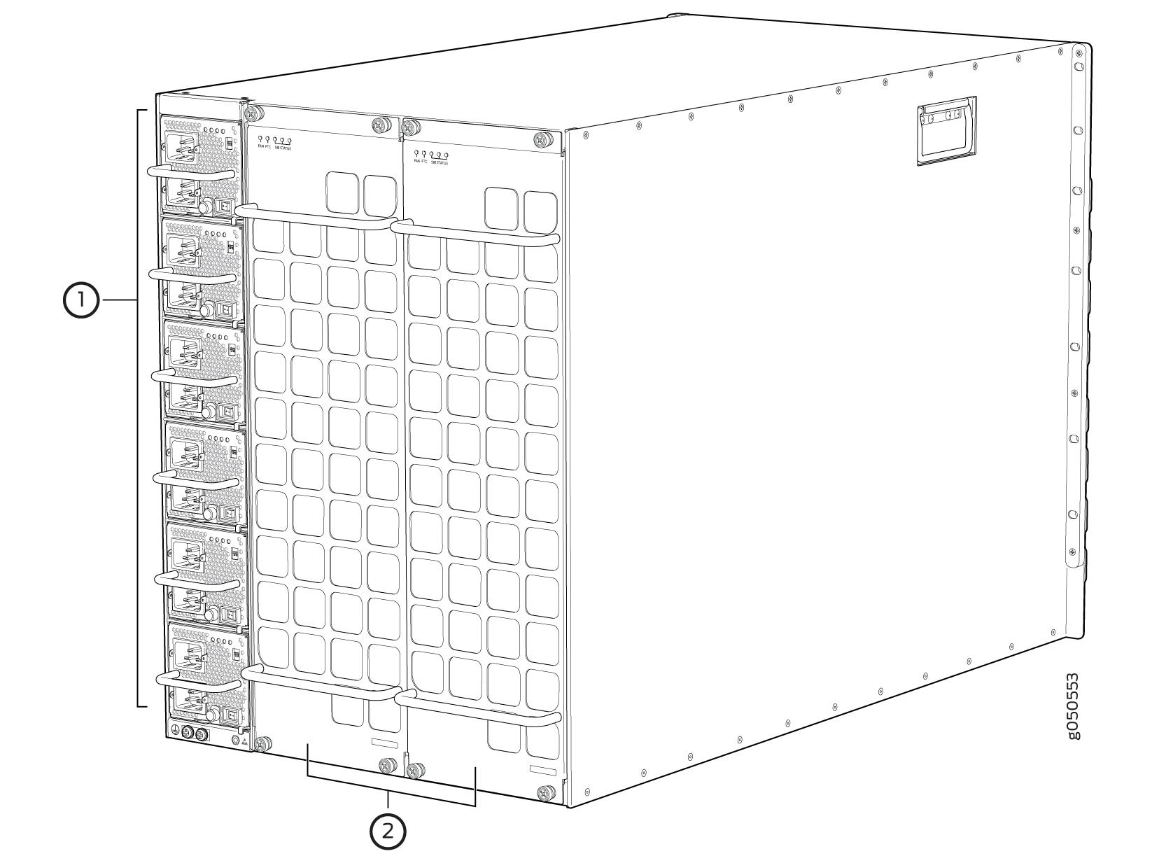
1 — Power supplies | 2 — Fan trays |
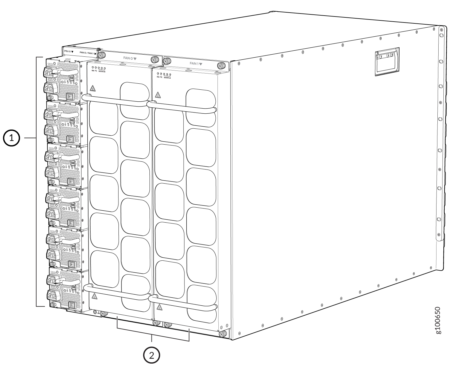
1 — Power supplies | 2 — Fan trays |
See Table 1 for the physical specifications for the fan trays.
|
Specification |
JNP10008-FAN |
JNP10008-FAN2 |
JNP10008-FAN3 |
|---|---|---|---|
|
Corresponding fan tray controller model |
JNP10008-FAN-CTLR |
JNP10008-FTC2 |
JNP10008-FTC3 |
|
Number of fan modules per fan tray |
11 |
22 |
22 |
|
Number of fan modules per chassis |
22 |
44 |
44 |
|
Fan numbering |
0 through 10 |
0 through 21 |
0 through 21 |
|
Volume flow per fan tray at 100% at 72° F |
720 cubic feet per minute (CFM) |
920 CFM |
1,080 CFM |
|
Volume flow per chassis at 100% at 72° F |
1580 CFM |
2050 CFM |
2400 CFM |
|
Switch fabric compatibility |
JNP10008-SF |
JNP10008-SF, JNP10008-SF3, or JNP10008-SF5 |
JNP10008-SF5 |
|
Introduced in Junos OS Release |
15.1X53-D30 |
19.2R1-S1 |
24.2R1 Evolved |
| Compatible power supplies | JNP10K-PWR-AC or JNP10K-PWR-DC | JNP10K-PWR-AC2 or JNP10K-PWR-DC2 |
JNP10K-PWR-AC3, JNP10K-PWR-DC3, or JNP10K-PWR-AC3H |
|
Height |
22.4 in. (56.9 cm) |
22.4 in. (56.9 cm) |
22.4 in. (56.9 cm) |
|
Width |
6.6 in. (16.8 cm) |
6.6 in. (16.8 cm) |
6.6 in. (16.8 cm) |
|
Depth |
4.0 in. (10.2 cm) without handles, 5.2 in. (13.2 cm) with handles |
5.5 in. (13.97 cm) without handles, 6.7 in. (17.01 cm) with handles |
5.8 in. (14.73 cm) without handles, 7.12 in. (18.08 cm) with handles |
|
Weight |
11.8 lb (5.4 kg) |
20 lb (9.07 kg) |
26 lb (11.8 kg) |
The array of fans in all the three models operate as a single unit. If an individual fan in the array fails, the entire fan tray must be replaced.
If you want to replace an existing fan tray while the router is running, remove only one fan tray. The router continues to operate for a limited time with a single operating fan tray without triggering a thermal alarm.
To avoid a thermal alarm, do not remove both fan trays while the router is operating.
The chassis will shut down if a thermal alarm is raised for more than three minutes.
The internal fan control board in each fan tray contains the LEDs for the associated fan tray controllers and the LEDs for the three SIBs directly behind the fan tray.
Fan Tray Controllers
The PTX10008 supports two fan tray controllers to provide the control logic and power to hot-insert and hot-remove a fan tray.
There are three fan tray controller models:
-
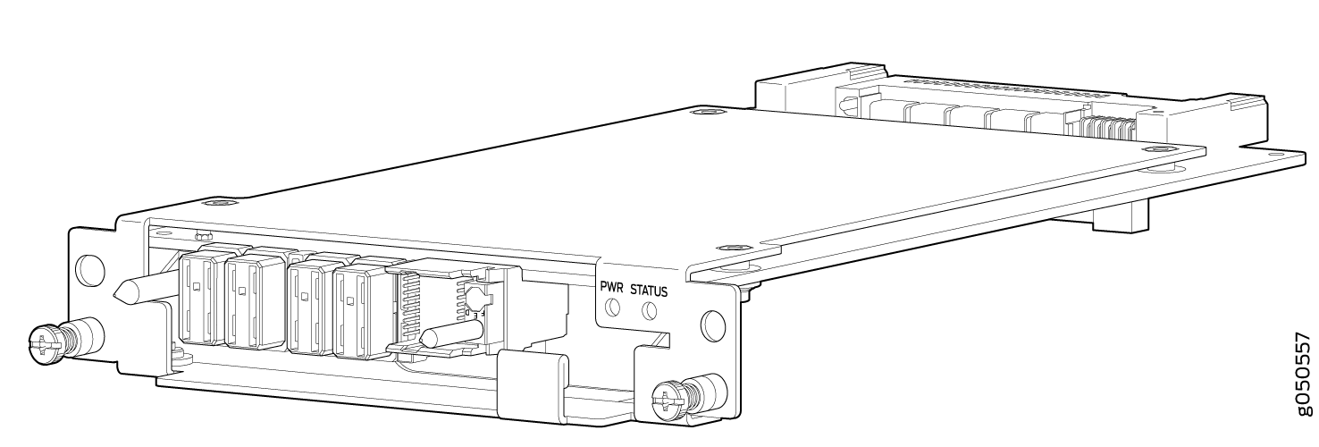
JNP10008-FAN-CTRL—Supports model JNP10008-FAN; see Figure 4.
-
JNP10008-FTC2—Supports JNP10008-FAN2 fan tray; see Figure 5.
-
JNP10008-FTC3—Supports JNP10008-FAN3 and JNP10008-FAN2 fan trays.
-
Table 2: Fan Tray Controller - Fan Tray Compatability Fan Tray Controller Compatible Fan Tray JNP10008-FAN-CTRL JNP10008-FAN JNP10008-FTC2 JNP10008-FAN2 JNP10008-FTC3 JNP10008-FAN3, JNP10008-FAN2 Warning:Do not mix the fan tray controller models. Use only the supported fan tray model for each fan tray controller model.
Note: If you are using JNP10008-FAN3 fan tray, you must use JNP10008-FTC3 fan tray controller and JNP10K-PWR-AC3, JNP10K-PWR-DC3, or JNP10K-PWR-AC3H power supplies. -
Figure 4: Fan Tray Controller JNP10008-FAN-CTRL
-
Figure 5: Fan Tray Controller JNP10008-FTC2 or JNP10008-FTC3
|
Specification |
JNP10008-FAN-CTRL |
JNP10008-FTC2 |
JNPR10008-FTC3 |
|---|---|---|---|
|
Corresponding fan tray model |
JNP10008-FAN |
JNP10008-FAN2 |
JNP10008-FAN3 |
|
Switch fabric compatibility |
JNP10008-SF |
JNP10008-SF, JNP10008-SF3, or JNP10008-SF5 |
JNP10008-SF5 |
|
Introduced in Junos OS Release |
15.1X53-D30 |
19.2R1 |
24.2R1 Evolved |
|
Height |
1.5 in. (3.81 cm) |
1.5 in. (3.81 cm) |
1.5 in. (3.81 cm) |
|
Width |
6.5 in. (15.24 cm) |
6.5 in. (15.24 cm) |
6.5 in. (15.24 cm) |
|
Depth |
9.3 in. (23.62 cm) |
9.4 in. (23.88 cm) |
9.4 in. (23.88 cm) |
|
Weight |
1.5 lb (0.68 kg) |
1.1 lb (0.5 kg) |
1.1 lb (0.5 kg) |
The system continually monitors the temperature of critical parts across the chassis and adjusts the chassis fan speed according to the temperature.
Junos OS software controls the fan speed.
Under
normal operating conditions, the fans in the fan tray run at less than full
speed. If one fan tray controller fails or appears
missing (such as when a SIB is being replaced), the other fan tray
controller sets the fans to full speed. This allows the router to continue
to operate normally as long as the remaining fans cool the chassis
sufficiently. Use the show chassis fan command to see the
status of individual fans and fan speed. The following examples of the
show chassis fan command show the fan status for a
system running JNP10008-FAN and JNP10008-FAN-CTRL:
This example shows the output from a JNP10008-SF fabric system running JNP10008-FAN and JNP10008-FAN-CTRL and standard Junos OS.
user@system> show chassis fan
      Item                      Status   RPM     Measurement
      Fan Tray 0 Fan 0          OK       6300    Spinning at normal speed
       Fan Tray 0 Fan 1          OK       6150    Spinning at normal speed
      Fan Tray 0 Fan 2          OK       6300    Spinning at normal speed
      Fan Tray 0 Fan 3          OK       6300    Spinning at normal speed
      Fan Tray 0 Fan 4          OK       6150    Spinning at normal speed
      Fan Tray 0 Fan 5          OK       6000    Spinning at normal speed
      Fan Tray 0 Fan 6          OK       6150    Spinning at normal speed
      Fan Tray 0 Fan 7          OK       6150    Spinning at normal speed
      Fan Tray 0 Fan 8          OK       6150    Spinning at normal speed
      Fan Tray 0 Fan 9          OK       6300    Spinning at normal speed
      Fan Tray 0 Fan 10         OK       6300    Spinning at normal speed
      Fan Tray 1 Fan 0          OK       6300    Spinning at normal speed
      Fan Tray 1 Fan 1          OK       6150    Spinning at normal speed
      Fan Tray 1 Fan 2          OK       6300    Spinning at normal speed
      Fan Tray 1 Fan 3          OK       6150    Spinning at normal speed
      Fan Tray 1 Fan 4          OK       6300    Spinning at normal speed
      Fan Tray 1 Fan 5          OK       6300    Spinning at normal speed
      Fan Tray 1 Fan 6          OK       6150    Spinning at normal speed
      Fan Tray 1 Fan 7          OK       6150    Spinning at normal speed
      Fan Tray 1 Fan 8          OK       6150    Spinning at normal speed
      Fan Tray 1 Fan 9          OK       6150    Spinning at normal speed
      Fan Tray 1 Fan 10         OK       6300    Spinning at normal speed
This example shows the output from a JNP10008-SF3 fabric system running JNP10008-FAN2 and JNP10008-FTC2 and standard Junos OS.
user@system> show chassis fan
Item                      Status   RPM     Measurement
      Fan Tray 0 Fan 0          OK       6450    Spinning at normal speed
      Fan Tray 0 Fan 1          OK       7950    Spinning at normal speed
      Fan Tray 0 Fan 2          OK       6450    Spinning at normal speed
      Fan Tray 0 Fan 3          OK       7950    Spinning at normal speed
      Fan Tray 0 Fan 4          OK       6450    Spinning at normal speed
      Fan Tray 0 Fan 5          OK       7950    Spinning at normal speed
      Fan Tray 0 Fan 6          OK       6600    Spinning at normal speed
      Fan Tray 0 Fan 7          OK       7950    Spinning at normal speed
      Fan Tray 0 Fan 8          OK       6450    Spinning at normal speed
      Fan Tray 0 Fan 9          OK       7800    Spinning at normal speed
      Fan Tray 0 Fan 10         OK       6450    Spinning at normal speed
      Fan Tray 0 Fan 11         OK       7950    Spinning at normal speed
      Fan Tray 0 Fan 12         OK       6450    Spinning at normal speed
      Fan Tray 0 Fan 13         OK       7800    Spinning at normal speed
      Fan Tray 0 Fan 14         OK       6450    Spinning at normal speed
      Fan Tray 0 Fan 15         OK       7800    Spinning at normal speed
      Fan Tray 0 Fan 16         OK       6450    Spinning at normal speed
      Fan Tray 0 Fan 17         OK       7950    Spinning at normal speed
      Fan Tray 0 Fan 18         OK       6450    Spinning at normal speed
      Fan Tray 0 Fan 19         OK       7800    Spinning at normal speed
      Fan Tray 0 Fan 20         OK       6300    Spinning at normal speed
      Fan Tray 0 Fan 21         OK       7800    Spinning at normal speed
      Fan Tray 1 Fan 0          OK       6450    Spinning at normal speed
      Fan Tray 1 Fan 1          OK       7950    Spinning at normal speed
      Fan Tray 1 Fan 2          OK       6600    Spinning at normal speed
      Fan Tray 1 Fan 3          OK       7950    Spinning at normal speed
      Fan Tray 1 Fan 4          OK       6600    Spinning at normal speed
      Fan Tray 1 Fan 5          OK       7950    Spinning at normal speed
      Fan Tray 1 Fan 6          OK       6600    Spinning at normal speed
      Fan Tray 1 Fan 7          OK       7950    Spinning at normal speed
      Fan Tray 1 Fan 8          OK       6600    Spinning at normal speed
      Fan Tray 1 Fan 9          OK       7950    Spinning at normal speed
      Fan Tray 1 Fan 10         OK       6450    Spinning at normal speed
      Fan Tray 1 Fan 11         OK       7950    Spinning at normal speed
      Fan Tray 1 Fan 12         OK       6450    Spinning at normal speed
      Fan Tray 1 Fan 13         OK       7800    Spinning at normal speed
      Fan Tray 1 Fan 14         OK       6450    Spinning at normal speed
      Fan Tray 1 Fan 15         OK       7800    Spinning at normal speed
      Fan Tray 1 Fan 16         OK       6450    Spinning at normal speed
      Fan Tray 1 Fan 17         OK       7950    Spinning at normal speed
      Fan Tray 1 Fan 18         OK       6450    Spinning at normal speed
      Fan Tray 1 Fan 19         OK       7800    Spinning at normal speed
      Fan Tray 1 Fan 20         OK       6450    Spinning at normal speed
      Fan Tray 1 Fan 21         OK       7650    Spinning at normal speed
This example shows the output from a JNP10008-SF3 fabric system running JNP10008-FAN2 and JNP10008-FTC2 and Junos OS Evolved.
user@system> show chassis fan
      Item                      Status   % RPM     Measurement
      Fan Tray 0 Fan 0          Ok       83%       8850 RPM
      Fan Tray 0 Fan 1          Ok       75%       10200 RPM
      Fan Tray 0 Fan 2          Ok       83%       8850 RPM
      Fan Tray 0 Fan 3          Ok       76%       10350 RPM
      Fan Tray 0 Fan 4          Ok       83%       8850 RPM
      Fan Tray 0 Fan 5          Ok       76%       10350 RPM
      Fan Tray 0 Fan 6          Ok       83%       8850 RPM
      Fan Tray 0 Fan 7          Ok       75%       10200 RPM
      Fan Tray 0 Fan 8          Ok       83%       8850 RPM
      Fan Tray 0 Fan 9          Ok       76%       10350 RPM
      Fan Tray 0 Fan 10         Ok       83%       8850 RPM
      Fan Tray 0 Fan 11         Ok       75%       10200 RPM
      Fan Tray 0 Fan 12         Ok       84%       9000 RPM
      Fan Tray 0 Fan 13         Ok       75%       10200 RPM
      Fan Tray 0 Fan 14         Ok       81%       8700 RPM
      Fan Tray 0 Fan 15         Ok       75%       10200 RPM
      Fan Tray 0 Fan 16         Ok       83%       8850 RPM
      Fan Tray 0 Fan 17         Ok       75%       10200 RPM
      Fan Tray 0 Fan 18         Ok       83%       8850 RPM
      Fan Tray 0 Fan 19         Ok       74%       10050 RPM
      Fan Tray 0 Fan 20         Ok       81%       8700 RPM
      Fan Tray 0 Fan 21         Ok       75%       10200 RPM
      Fan Tray 1 Fan 0          Ok       83%       8850 RPM
      Fan Tray 1 Fan 1          Ok       75%       10200 RPM
      Fan Tray 1 Fan 2          Ok       83%       8850 RPM
      Fan Tray 1 Fan 3          Ok       76%       10350 RPM
      Fan Tray 1 Fan 4          Ok       83%       8850 RPM
      Fan Tray 1 Fan 5          Ok       76%       10350 RPM
      Fan Tray 1 Fan 6          Ok       84%       9000 RPM
      Fan Tray 1 Fan 7          Ok       76%       10350 RPM
      Fan Tray 1 Fan 8          Ok       83%       8850 RPM
      Fan Tray 1 Fan 9          Ok       75%       10200 RPM
      Fan Tray 1 Fan 10         Ok       83%       8850 RPM
      Fan Tray 1 Fan 11         Ok       75%       10200 RPM
      Fan Tray 1 Fan 12         Ok       81%       8700 RPM
      Fan Tray 1 Fan 13         Ok       75%       10200 RPM
      Fan Tray 1 Fan 14         Ok       83%       8850 RPM
      Fan Tray 1 Fan 15         Ok       75%       10200 RPM
      Fan Tray 1 Fan 16         Ok       83%       8850 RPM
      Fan Tray 1 Fan 17         Ok       75%       10200 RPM
      Fan Tray 1 Fan 18         Ok       83%       8850 RPM
      Fan Tray 1 Fan 19         Ok       76%       10350 RPM
      Fan Tray 1 Fan 20         Ok       81%       8700 RPM
      Fan Tray 1 Fan 21         Ok       74%       10050 RPM
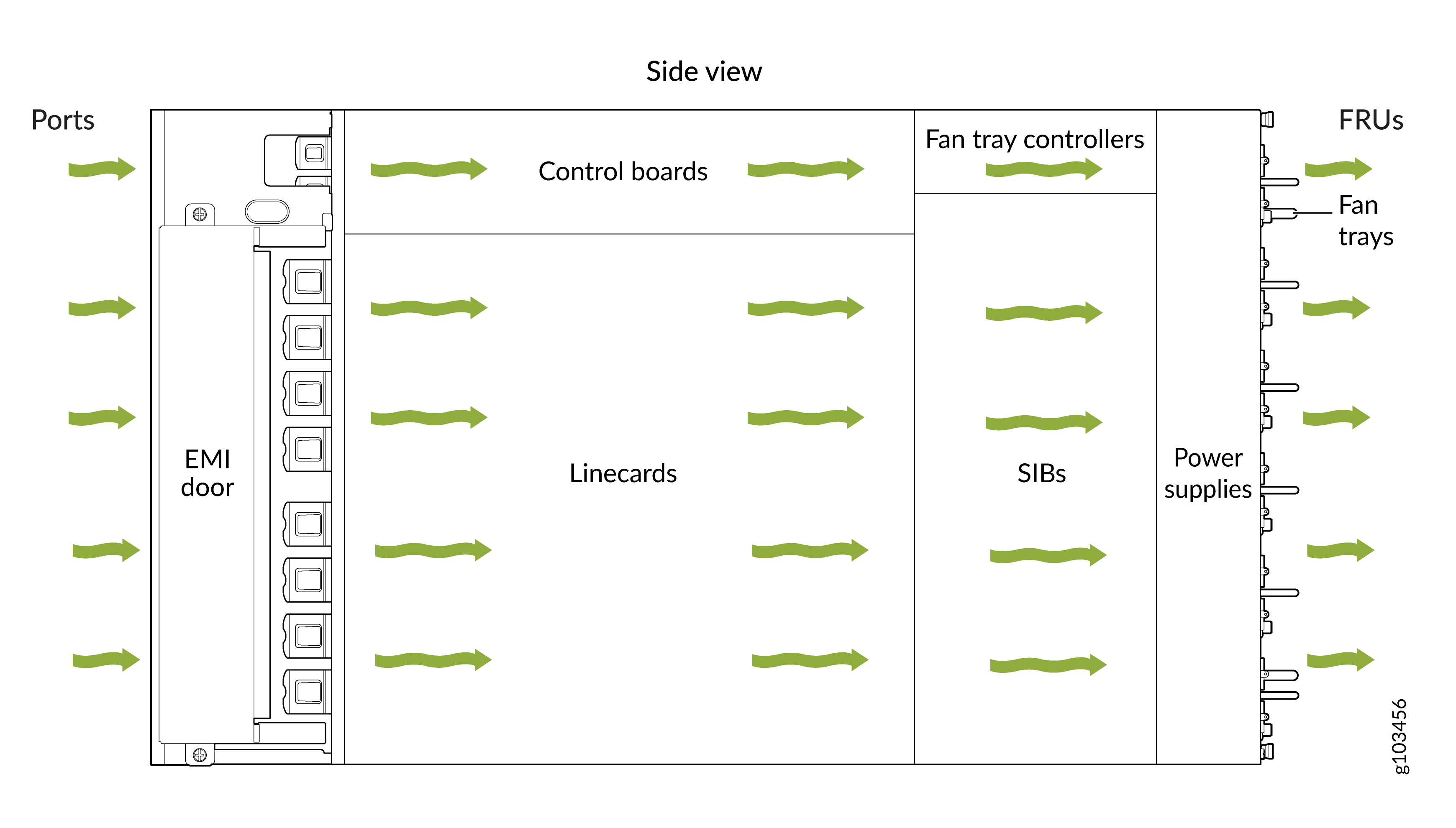
Airflow Direction in the PTX10008
The air intake to cool the chassis is located on the port (line card) side of the chassis. Air flows into the chassis from the ports in the RCBs and line cards, through the Switch Interface Boards (SIBs), and exits from the fan trays and the power supplies. See Figure 6.
The fan tray continues to operate indefinitely and provide sufficient cooling even when a single fan fails, provided the room temperature is within the operating range. You can check the status of fans by viewing the LEDs on each fan tray. See PTX10008 Fan Tray LEDs and Fan Tray Controller LEDs.
You cannot replace a single fan. If one or more fans fail, you must replace the entire fan tray.
In addition to the fans in the fan trays, there is an internal fan in each power supply that also helps to cool components, such as the line cards.
See Also
PTX10008 Fan Tray LEDs and Fan Tray Controller LEDs
Each fan tray has a set of LEDs, and each corresponding fan tray controller also has a set of LEDs.
Fan Tray LEDs
Each fan tray has a set of LEDs that represent the status of the fans in the fan tray, the fan tray controller, and the three Switch Interface Boards (SIBs). The fan tray LEDs are located in the top left corner of each fan tray. Figure 7 shows the location of the LEDs on JNP10008-FAN fan trays. See Figure 8 for the location of LEDs on the JNP10008-FAN2 fan trays.
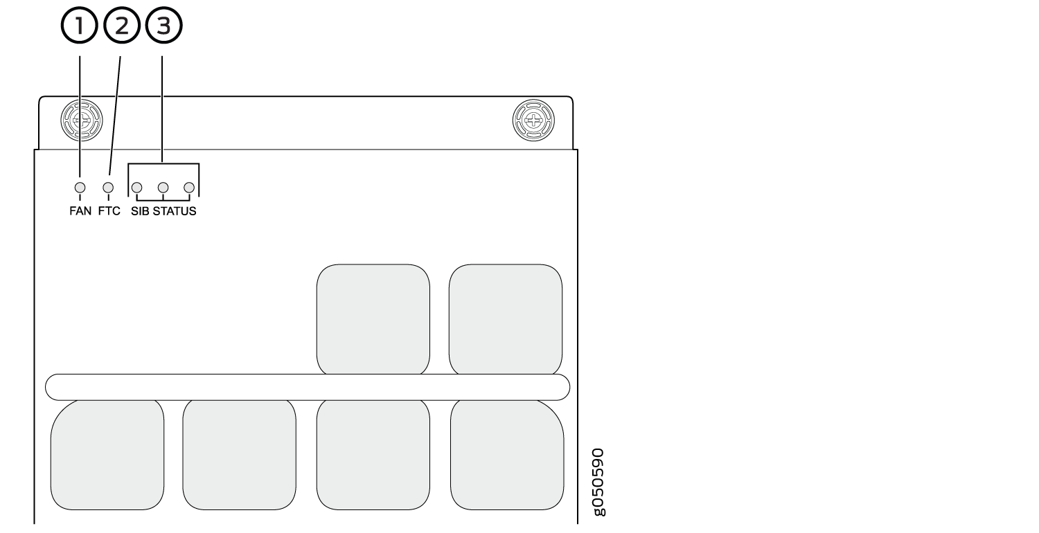
1 — Fan status LED | 3 — SIB status LEDs (SIB 0 through SIB 2 for the left fan tray and SIB 3 through SIB 5 for the right fan tray) |
2 — Fan tray controller status LED |
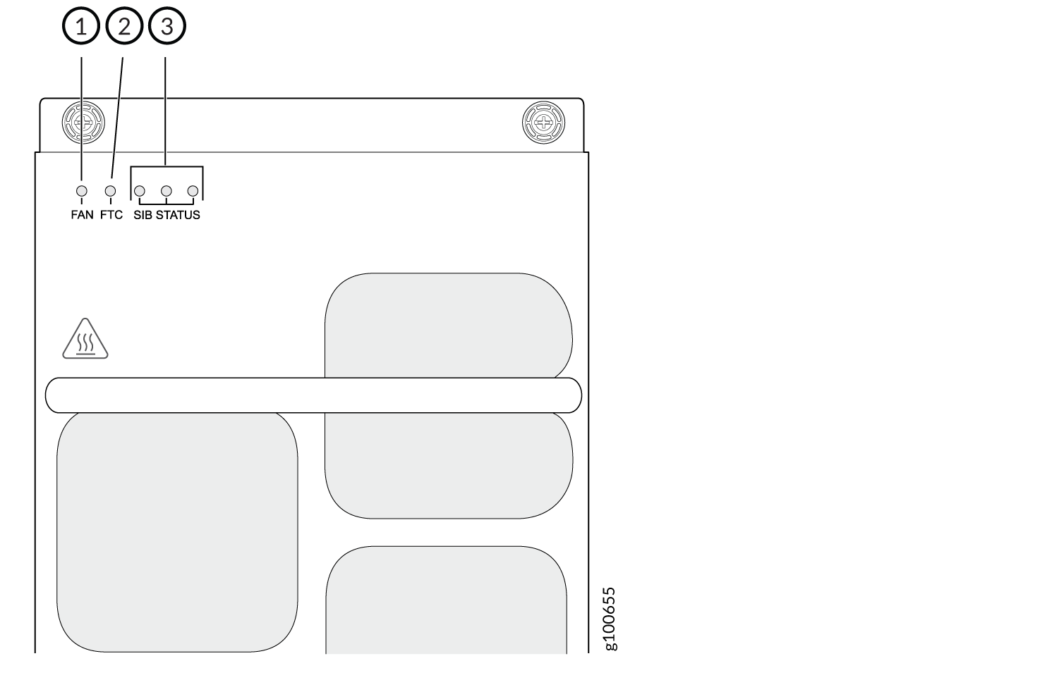
1 — Fan status LED | 3 — SIB status LEDs (SIB 0 through SIB 2 for the left fan tray and SIB 3 through SIB 5 for the right fan tray). |
2 — Fan tray controller status LED |
Table 4 describes the functions of the fan tray LEDs.
Name |
Color |
State |
Description |
|---|---|---|---|
FAN (fan status) |
Green |
On steadily |
All fans are operating normally. The system has verified that the fan tray is engaged, that the airflow is in the correct direction, and that all fans are operating correctly. |
Yellow |
Blinking |
An error has been detected in one or more fans in the fan tray. Replace the fan tray as soon as possible. Either the fan has failed or it has become disconnected. To maintain proper airflow through the chassis, leave the fan tray installed in the chassis until you are ready to replace it. |
|
None |
Off |
The fan is not receiving power from the fan tray controller. |
|
FTC (fan tray controller status) |
Green |
On steadily |
The fan tray controller is online and is operating normally. |
Yellow |
Blinking |
An error has been detected in the fan tray controller. Replace the fan tray controller as soon as possible. The fan tray controller is located behind the fan tray above the SIBs. To maintain proper airflow through the chassis, leave the fan tray installed in the chassis until you are ready to replace the fan tray controller. |
|
None |
Off |
The fan tray controller is not receiving power. |
|
SIB Status (SIB 0 status) |
Green |
On steadily |
The left-most SIB in the chassis is online. |
Yellow |
Blinking |
An error has been detected in SIB 0. Replace the SIB as soon as possible. The SIB is located behind the left fan tray and is the left-most SIB in the chassis. To maintain proper airflow through the chassis, leave the fan tray installed in the chassis until you are ready to replace the SIB. |
|
None |
Off |
The SIB is offline. |
|
SIB Status (SIB 1 status) |
Green |
On steadily |
The center SIB behind the left fan tray is online. |
Yellow |
Blinking |
An error has been detected in SIB 1. Replace the SIB as soon as possible. The SIB is located behind the left fan tray and is the middle SIB in the group of 3. To maintain proper airflow through the chassis, leave the fan tray installed in the chassis until you are ready to replace the SIB. |
|
None |
Off |
The SIB is offline. |
|
SIB Status (SIB 2 status) |
Green |
On steadily |
The right-most SIB behind the left fan tray is online. |
Yellow |
Blinking |
An error has been detected in SIB 2. Replace the SIB as soon as possible. The SIB is located behind the left fan tray and is the right-most SIB in the group of 3. To maintain proper airflow through the chassis, leave the fan tray installed in the chassis until you are ready to replace the SIB. |
|
None |
Off |
The SIB is offline. |
|
SIB Status (SIB 3 status) |
Green |
On steadily |
The left-most SIB behind the right fan tray is online. |
Yellow |
Blinking |
An error has been detected in SIB 3. Replace the SIB as soon as possible. The SIB is located behind the right fan tray and is the left-most SIB in the group of 3. To maintain proper airflow through the chassis, leave the fan tray installed in the chassis until you are ready to replace the SIB. |
|
None |
Off |
The SIB is offline. |
|
SIB Status (SIB 4 status) |
Green |
On steadily |
The center SIB behind the right fan tray is online. |
Yellow |
Blinking |
An error has been detected in SIB 4. Replace the SIB as soon as possible. The SIB is located behind the right fan tray and is the middle SIB in the group of 3. To maintain proper airflow through the chassis, leave the fan tray installed in the chassis until you are ready to replace the SIB. |
|
None |
Off |
The SIB is offline. |
|
SIB Status (SIB 5 status) |
Green |
On steadily |
The right-most SIB behind the right fan tray is online. |
Yellow |
Blinking |
An error has been detected in SIB 5. Replace the SIB as soon as possible. The SIB is located behind the right fan tray and is the right-most SIB in the group of 3. To maintain proper airflow through the chassis, leave the fan tray installed in the chassis until you are ready to replace the SIB. |
|
None |
Off |
The SIB is offline. |
Fan Tray Controller LEDs
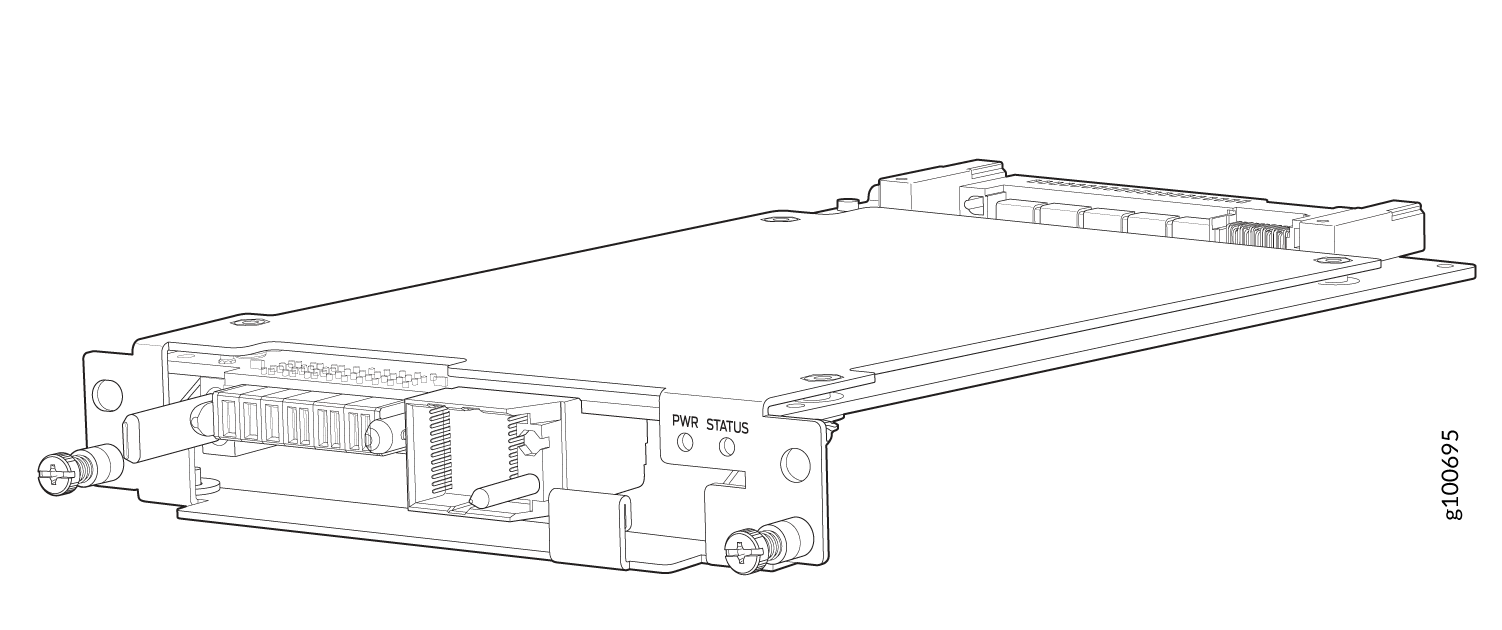
All models of fan tray controller have the same LEDs. The fan tray controller LEDs are visible only when the associated fan tray is removed. The fan tray controller LEDs are located on the right of the controller panel. Figure 9 shows the location of the LEDs on the JNP10008-FAN-CTRL or the JNP10008-FTC2 fan tray controller faceplate.
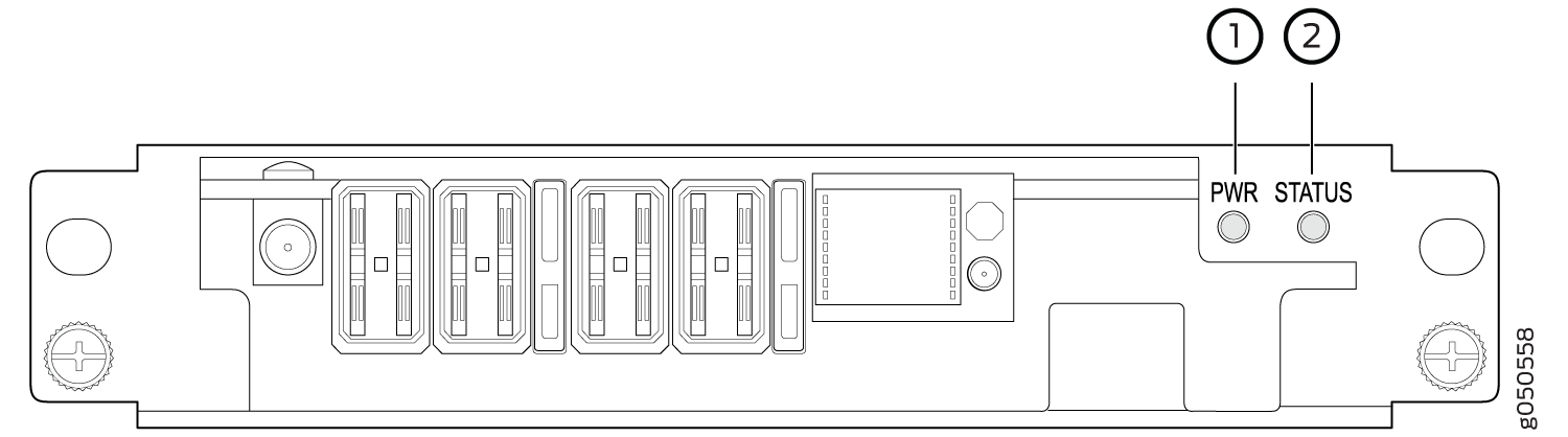
1 — Fan tray controller power | 2 — Fan tray controller status |
Table 5 describes the functions of the fan tray controller LEDs.
Name |
Color |
State |
Description |
|---|---|---|---|
PWR (fan tray controller power) |
Green |
On steadily |
The fan tray controller has power and is operating normally. |
Yellow |
Blinking |
A power error has been detected in the fan tray controller. Replace the fan tray controller as soon as possible. To maintain proper airflow through the chassis, leave the fan tray installed in the chassis until you are ready to replace the fan tray controller. |
|
None |
Off |
The fan tray controller is not powered on or is not receiving power. |
|
STATUS (fan tray controller status) |
Green |
On steadily |
The fan tray controller is online and is operating normally. |
Yellow |
Blinking |
An error has been detected in the fan tray controller. Replace the fan tray controller as soon as possible. To maintain proper airflow through the chassis, leave the fan tray installed in the chassis until you are ready to replace the fan tray controller. |
|
None |
Off |
The fan tray controller is not receiving power. |