PTX10008 Chassis
The PTX10008 chassis houses the hardware components. The chassis components include the fan trays, fan tray controllers, power supplies, Routing and Control Boards (RCBs), line cards, optional cable management system, and the status panel.
PTX10008 Chassis Physical Specifications
The PTX10008 modular chassis is a rigid sheet-metal structure that houses the other router components. You can mount up to three PTX10008 routers in a standard 19-in. 4-post rack (42 U) provided the rack can handle the combined weight and there is adequate power and cooling. Table 1 summarizes the physical specifications of the chassis. See Figure 1.
Description |
Weight |
Height |
Width |
Depth |
|---|---|---|---|---|
Chassis, spare |
145.2 lb (65.86 kg) |
22.6 in. (57.4 cm) |
17.4 in. (44.2 cm) Note:
The outer edges of the chassis flange extend the width to 19 in. (48.3 cm). |
32 in. (81.28 cm) chassis only |
Chassis base AC configuration |
273 lb (123.83 kg) |
22.6 in. (57.4 cm) |
17.4 in. (44.2 cm) Note:
The outer edges of the chassis flange extend the width to 19 in. (48.3 cm). |
35 in. (88.9 cm) with JNP10K-PWR-AC power supplies 42.4 in. (107.7 cm) with front door with EMI deflectors |
Chassis base DC configuration |
270 lb (122.47 kg) |
22.6 in. (57.4 cm) |
17.4 in. (44.2 cm) Note:
The outer edges of the chassis flange extend the width to 19 in. (48.3 cm). |
35 in. (88.9 cm) with JNP10K-PWR-DC power supplies 42.4 in. (107.7 cm) with front door with EMI deflectors |
Chassis BASE3 AC configuration |
394.05 lb (178.74 kg) |
22.6 in. (57.4 cm) |
17.4 in. (44.2 cm) Note:
The outer edges of the chassis flange extend the width to 19 in. (48.3 cm). |
36.7 in. (93.2 cm) with JNP10K-PWR-AC2 power supplies 42.8 in. (108.7 cm) with front door with EMI deflectors |
Chassis PREM2 AC configuration |
390.85 lb (177.29 kg) |
22.6 in. (57.4 cm) |
17.4 in. (44.2 cm) Note:
The outer edges of the chassis flange extend the width to 19 in. (48.3 cm). |
36.7 in. (93.2 cm) with JNP10K-PWR-AC2 power supplies 42.8 in. (108.7 cm) with front door with EMI deflectors |
Chassis PREM2 DC configuration |
375.65 (170.39 kg) |
22.6 in. (57.4 cm) |
17.4 in. (44.2 cm) Note:
The outer edges of the chassis flange extend the width to 19 in. (48.3 cm). |
36.7 in. (93.2 cm) with JNP10K-PWR-DC2 power supplies 42.8 in. (108.7 cm) with front door with EMI deflectors |
Chassis PREMIUM redundant AC configuration |
353 lb (160.12 kg) |
22.6 in. (57.4 cm) |
17.4 in. (44.2 cm) Note:
The outer edges of the chassis flange extend the width to 19 in. (48.3 cm). |
35 in. (88.9 cm) with JNP10K-PWR-AC power supplies 42.4 in. (107.7 cm) with front door with EMI deflectors |
Chassis PREMIUM redundant DC configuration |
350.6 lb (159 kg) |
22.6 in. (57.4 cm) |
17.4 in. (44.2 cm) Note:
The outer edges of the chassis flange extend the width to 19 in. (48.3 cm). |
35 in. (88.9 cm) with JNP10K-PWR-DC power supplies 42.4 in. (107.7 cm) with front door with EMI deflectors |
Chassis redundant AC PTX10008-PREM3 configuration |
421.25 lb (191.07 kg) |
22.6 in. (57.4 cm) |
17.4 in. (44.2 cm) Note:
The outer edges of the chassis flange extend the width to 19 in. (48.3 cm). |
36.7 in. (93.2 cm) with JNP10K-PWR-AC2 power supplies 42.8 in. (108.7 cm) with front door with EMI deflectors |
PTX10K-LC1101 Line Card |
27 lb (12.2 kg) |
1.89 in. (4.8 cm) |
17.2 in. (43.7 cm) |
20.54 in. (52.2 cm) |
PTX10K-LC1102 Line Card |
22.6 lb (10.2 kg) |
1.89 in. (4.8 cm) |
17.2 in. (43.7 cm) |
20.54 in. (52.2 cm) |
PTX10K-LC1104 Line Card |
32 lb (14.5 kg) |
1.89 in. (4.8 cm) |
17.2 in. (43.7 cm) |
20.54 in.(52.2 cm) |
PTX10K-LC1105 Line Card |
28.5 lb (12.9 kg) |
1.89 in. (4.8 cm) |
17.2 in. (43.7 cm) |
20.54 in.(52.2 cm) |
QFX10000-60S-6Q Line Card |
21.4 lb (9.7 kg) |
1.89 in. (4.8 cm) |
17.2 in. (43.7 cm) |
20.54 in.(52.2 cm) |
|
PTX10K-LC1201-36CD |
35 lb (15.88 kg) |
1.89 in. (4.8 cm) |
17.2 in. (43.7 cm) |
21.3 in. (54.1 cm) |
|
PTX10K-LC1202-36MR |
21 lb (9.5 kg) |
1.89 in. (4.8 cm) |
17.2 in. (43.68 cm) |
21.3 in. (54.1 cm) |
|
PTX10K-LC1301-36DD |
36.2 lb (16.5 kg) |
1.89 in. (4.8 cm) |
17.2 in. (43.7 cm) |
21.3 in. (54.1 cm) |
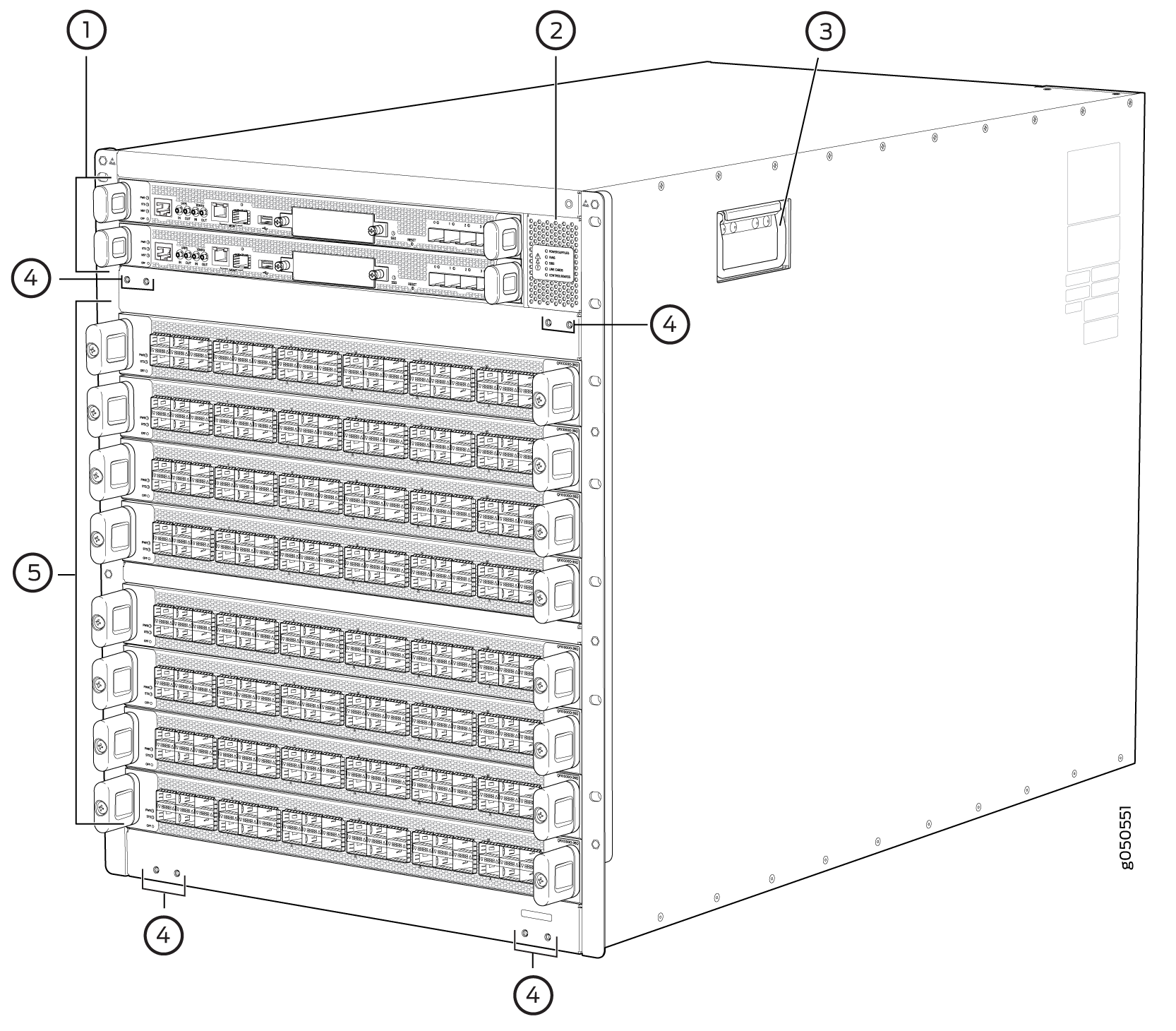
1 — RCBs | 4 — Mounting holes for front door |
2 — Status panel | 5 — Line cards |
3 — Handles |
The handles on each side of the chassis facilitate the fine-tune positioning of the chassis on the base brackets. Do not use the handles to lift the chassis, even when the chassis is empty. See Mount the PTX10008 by Using the JNP10004-RMK-4POST Rack Mount Kit, Mount the PTX10008 by Using the EX-MOD-RMK-4POST Rack Mount Kit, or Mount the PTX10008 by Using the JNP10K-RMK-4PST-XT Rack Mount Kit for instructions for properly moving a loaded chassis.
See Also
PTX10008 Field-Replaceable Units
Field-replaceable units (FRUs) are router components that you can replace at your site. The router uses the following types of FRUs:
Hot-insertable and hot-removable—You can remove and replace these components without powering off the router or disrupting the routing function.
Hot-pluggable—You can remove and replace these components without powering off the router, but the routing function is interrupted until you replace the component.
Table 2 lists the FRUs and their types for the PTX10008 routers.
FRU |
Type |
|---|---|
Power supplies |
Hot-insertable and hot-removable. |
Fan trays |
Hot-insertable and hot-removable. |
Fan tray controllers |
Hot-insertable and hot-removable. |
Routing and Control Boards (RCBs) |
Redundant configuration:
Base configuration:
|
Switch Interface Boards (SIBs) |
SIBs are hot-insertable and hot-removable. We recommend that you take SIBs offline before removing them to avoid traffic loss while the router fabric is being reconfigured. Use the following command: user@router> request chassis sib slot slot-number offline |
Line cards |
Hot-insertable. We recommend that you take line cards offline before removing them. Use the following command: user@router> request chassis fpc-slot slot-number offline |
Optical transceivers See PTX10008 Optical Transceiver and Cable Support for how to find detailed specifications and the Junos OS release in which the transceivers were introduced. |
Hot-insertable and hot-removable. |
Line cards are not part of the base or redundant configuration. You must order them separately.
If you have a Juniper Care service contract, register any addition, change, or upgrade of hardware components at https://www.juniper.net/customers/support/tools/updateinstallbase/. Failure to do so can result in significant delays if you need replacement parts. This note does not apply if you replace an existing component with the same type of component.
See Also
PTX10008 Status Panel
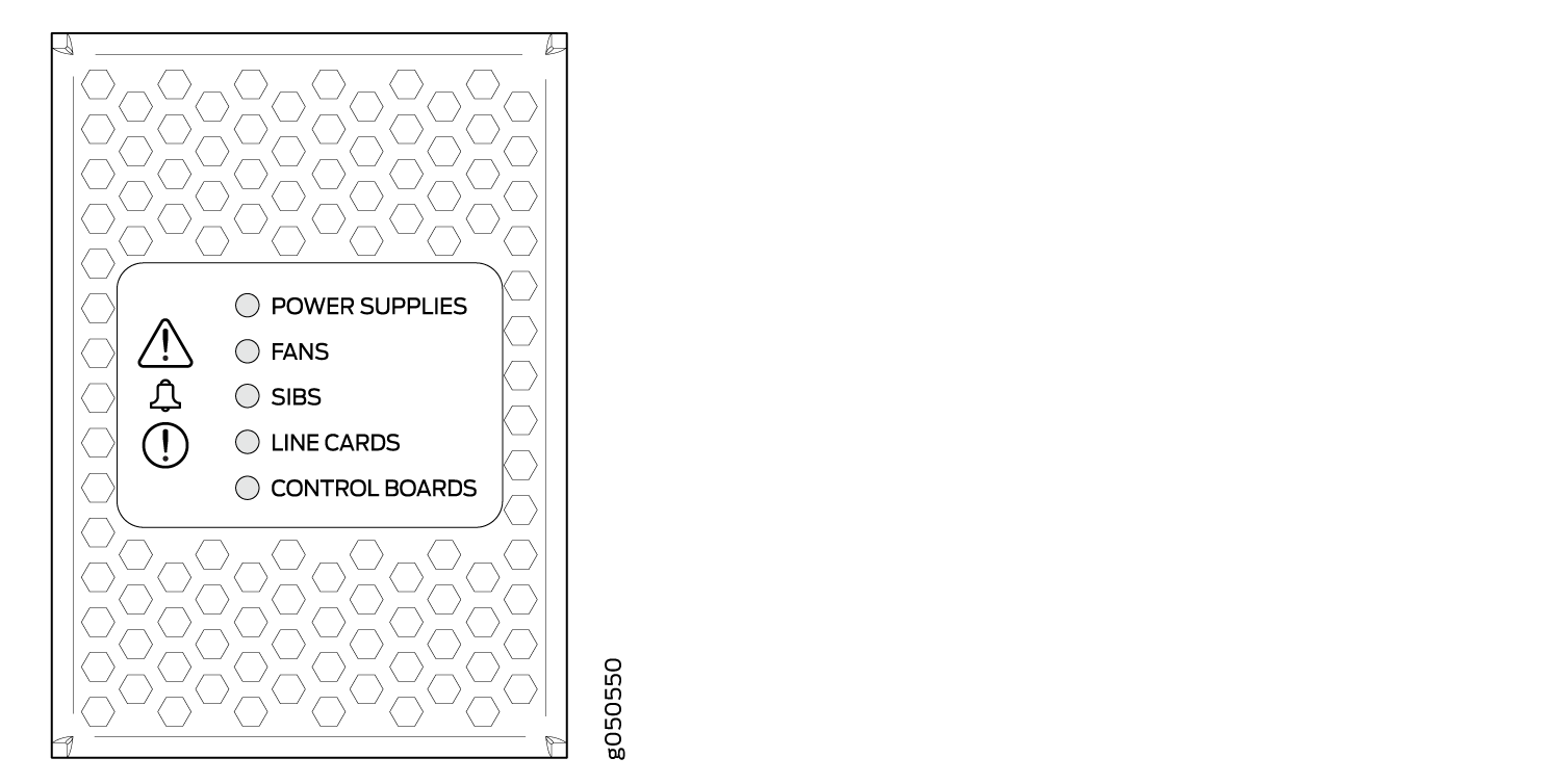
The status panel of the PTX10008 has two purposes:
Shows the overall status of the chassis
Indicates the type of power bus internal to the chassis
Some chassis ship with an enhanced power bus to future-proof the chassis for potential power growth.
The status panel indicates the chassis status through a set of five bicolor LEDs. See Figure 2 for a chassis status panel with the standard power bus.
Other chassis also have the same set of five bicolor LEDs, but also have an azure blue line to indicate the presence of the enhanced power bus (see Figure 3).
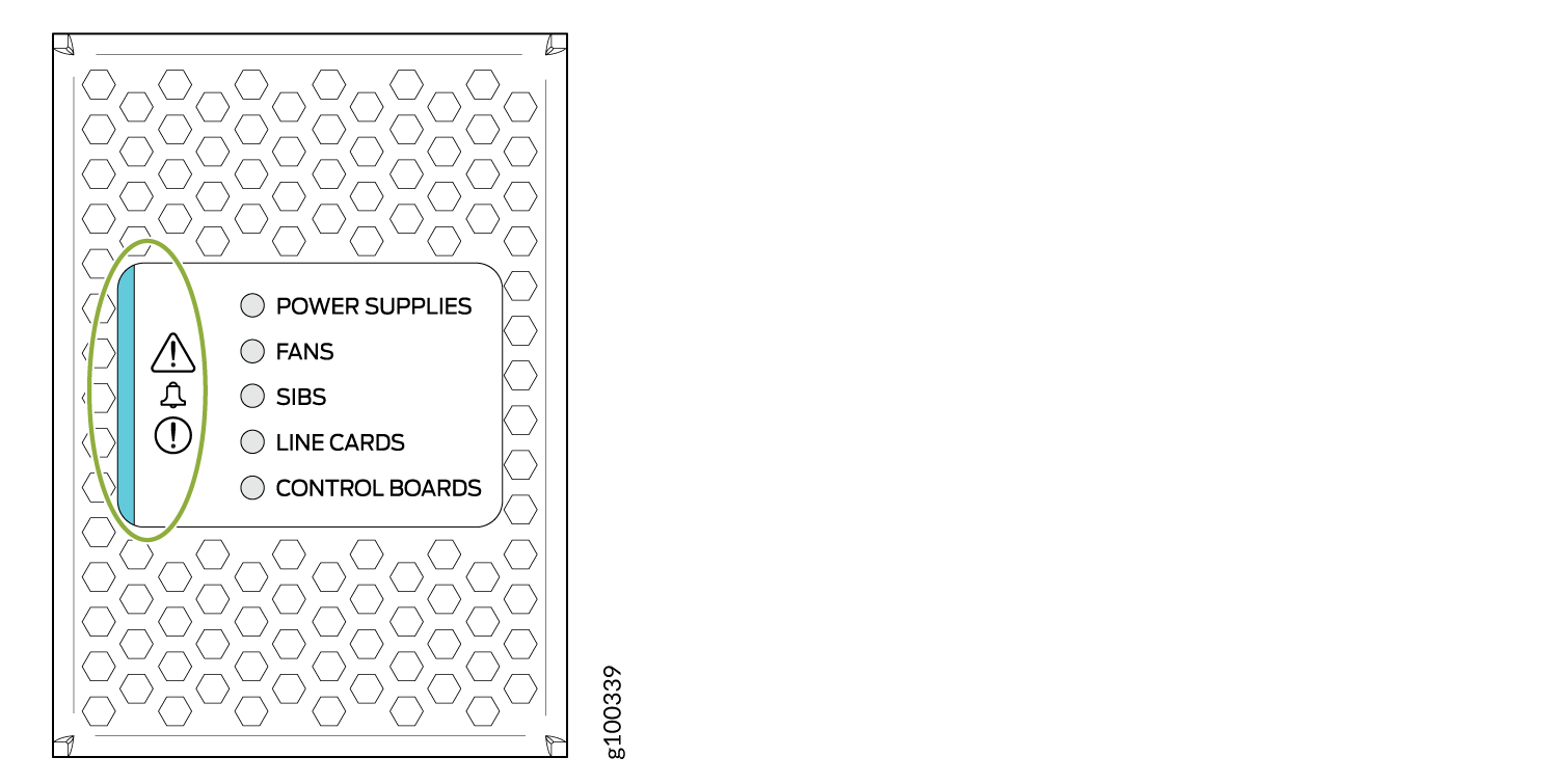
Table 3 describes the status panel LEDs.
|
Name |
Color |
State |
Description |
|---|---|---|---|
|
! Minor alarm (Triangle warning symbol) |
Yellow |
Off |
No minor alarms are active. |
|
On steadily |
A minor alarm is active. |
||
|
! Major alarm (Circle warning symbol) |
Red |
Off |
No major alarms are active. |
|
On steadily |
A major alarm is active. |
||
|
POWER SUPPLIES |
Green |
On steadily |
All of the power supplies are online and operating normally. |
|
Yellow |
On steadily (if Junos OS Evolved is installed in your router)/Blinking (if Junos OS is installed in your router) |
One or more of the power supplies has an error. |
|
|
None |
Off |
None of the power supplies is receiving power. |
|
|
FANS |
Green |
On steadily |
The fans and the fan tray controllers are online and operating normally. |
|
Yellow |
On steadily (if Junos OS Evolved is installed in your router)/Blinking (if Junos OS is installed in your router) |
There is an error in a fan or in one of the fan tray controllers. |
|
|
None |
Off |
The fan tray controllers and fan trays are not receiving power. |
|
|
SIBS |
Green |
On steadily |
At least one installed Switch Interface Board (SIB) is online. |
|
Yellow |
On steadily (if Junos OS Evolved is installed in your router)/Blinking (if Junos OS is installed in your router) |
There is a hardware error in one or more SIBs. |
|
|
None |
Off |
All the SIBs are offline. |
|
|
LINE CARDS |
Green |
On steadily |
At least one installed line card is online. |
|
Yellow |
On steadily (if Junos OS Evolved is installed in your router)/Blinking (if Junos OS is installed in your router) |
There is a hardware error in one or more line cards. |
|
|
None |
Off |
All the line cards are offline. |
|
|
CONTROL BOARDS |
Green |
On steadily |
All installed Routing and Control Boards (RCBs) are online. |
|
Yellow |
On steadily (if Junos OS Evolved is installed in your router)/Blinking (if Junos OS is installed in your router) |
One or more RCBs have an error condition. |
|
|
None |
Off |
The installed RCBs are offline. |
See Also
PTX10008 Optional Equipment
The PTX10008 routers supports the cable management system (JLC-CBL-MGMT-KIT) as an optional equipment:
PTX10008 Cable Management System
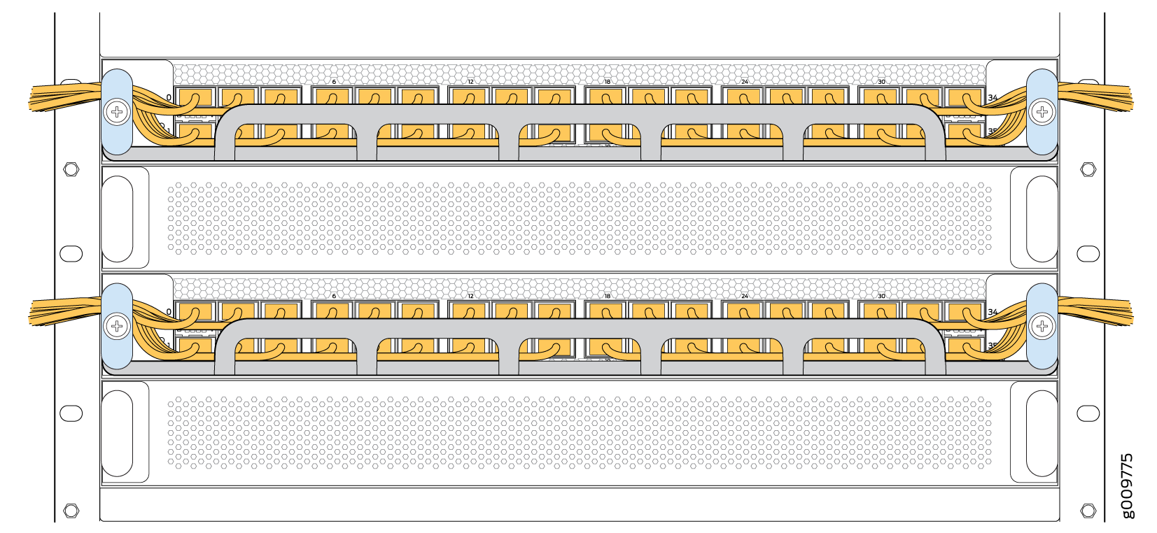
You can use the PTX10008 cable management system (see Figure 4) to route optical cables away from the line-card ports for better airflow through the chassis. Using this optional system also makes it easier to use cable ties or strips to organize the cabling.
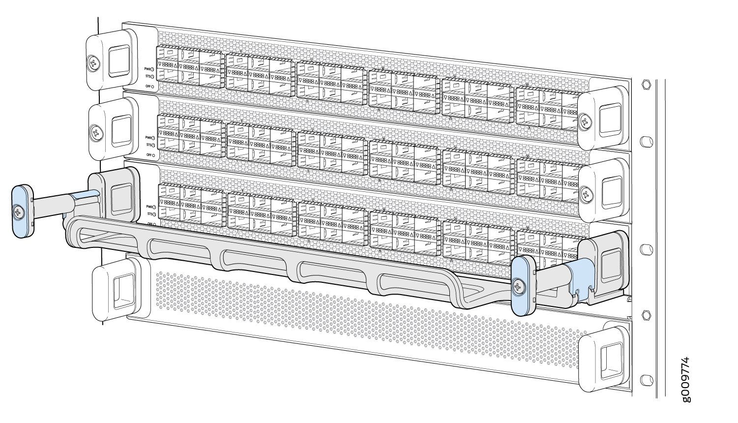
The cable management system comprises a set of handle extensions and a tray that snaps to the extensions (see Figure 5) for an individual line card. You can use the handle extensions with or without the cable tray. You don’t need to remove the handle extensions if you want to remove a line card.
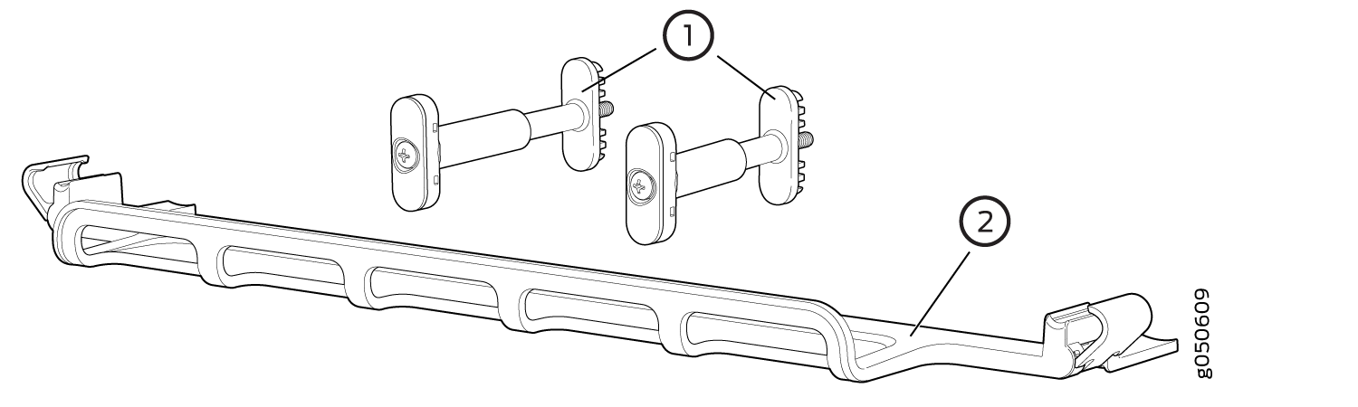
1 — Handle extensions | 2 — Cable tray |
Cables are draped across or under the handle extensions and then secured with cable wraps (see Figure 6).