PTX10008 Line Card Components and Descriptions
The line cards in PTX10008 routers combine a Packet Forwarding Engine and Ethernet interfaces in a single assembly. Line cards are field-replaceable units (FRUs) that can be installed in the line card slots on the front of the router chassis. The PTX10008 chassis supports up to eight line cards. Line cards are associated to the switch fabric for their system. See Table 1 for line cards that operate with the JNP10008-SF switch fabric, Table 2 for information about the line cards that operate with the JNP10008-SF3 switch fabric, and Table 3 for information about the line cards that operate with the JNP10008-SF5 switch fabric.
|
Line Card |
Description |
Dimensions (W x H x D) |
Net Shipping Weight |
|---|---|---|---|
|
PTX10K-LC1101 |
30-port 100-Gigabit or 40-Gigabit Ethernet |
17.2 in. x 1.89 in x 20.5 in 43.68 cm x 4.8 cm x 52.07 cm |
27 lbs 12.2 kg |
|
PTX10K-LC1102 |
36-port 40-Gigabit Ethernet; 12 ports support either 100-Gigabit or 40-Gigabit Ethernet |
17.2 in. x 1.89 in x 20.5 in 43.68 cm x 4.8 cm x 52.07 cm |
22.6 lbs 10.25 kg |
|
PTX10K-LC1104 |
6-port DWDM with MACsec with flexible modulation at 100-Gbps, 150-Gbps, and 200-Gbps |
17.2 in. x 1.89 in x 20.5 in 43.68 cm x 4.8 cm x 52.07 cm |
32 lbs 14.5 kg |
|
PTX10K-LC1105 |
30-port 100-Gigabit or 40-Gigabit Ethernet with MACsec |
17.2 in. x 1.89 in x 20.5 in 43.68 cm x 4.8 cm x 52.07 cm |
28.5 lbs 12.93 kg |
|
QFX10000-60S-6Q |
60-port 10-Gigabit or 1-Gigabit Ethernet; 2-port of 40-Gigabit or 100-Gigabit Ethernet; 4 port of 40-Gigabit |
17.2 in. x 1.89 in x 20.5 in 43.68 cm x 4.8 cm x 52.07 cm |
9.7 lb 4.39 kg |
|
Line Card |
Description |
Dimensions (W x H x D) |
Net Shipping Weight |
|---|---|---|---|
|
PTX10K-LC1201-36CD |
14.4 Tbps—36-port 400-Gigabit, 200-Gigabit, 100-Gigabit, 50-Gigabit, 25-Gigabit, or 10-Gigabit Ethernet |
17.2 in. x 1.89 in. x 21.3 in. 43.68 cm x 4.8 cm x 54.1 cm |
35 lb (15.88 kg) |
|
PTX10K-LC1202-36MR |
4.8 Tbps—32 ports capable of supporting 100-Gbps, 4 ports capable of supporting 400-Gbps speed. |
17.2 in. x 1.89 in. x 21.3 in. 43.68 cm x 4.8 cm x 54.1 cm |
21 lb (9.5 kg) |
|
PTX10K-LC1301-36DD |
28.8 Tbps—36-port line card that offers a line rate throughput of 28.8 Tbps. The 36 high-density 800-Gigabit Ethernet (800GbE) QSFP-DD ports support speeds of up to 800 Gbps. The maximum throughput that the line card offers in PTX10008 routers with JNP10008-SF3 installed is 12.8 Tbps. The support for JNP10008-SF3 is available from Junos OS Evolved Release 25.4R1-S1. |
17.2 in. x 1.89 in. x 21.3 in. 43.68 cm x 4.8 cm x 54.1 cm |
36.2 lb (16.5 kg) |
|
Line Card |
Description |
Dimensions (W x H x D) |
Net Shipping Weight |
|---|---|---|---|
|
PTX10K-LC1201-36CD |
36-port line card that provides a line rate throughput of 14.4 Tbps. The 36 QSFP56-DD ports support a speed of up to 400 Gbps. |
17.2 in. x 1.89 in. x 21.3 in. 43.68 cm x 4.8 cm x 54.1 cm |
35 lb (15.88 kg) |
|
PTX10K-LC1202-36MR |
36-port line card that provides a line rate throughput of 4.8 Tbps. The line card has 32 QSFP28 ports, each capable of supporting a maximum speed of 100 Gbps, and four QSFP56-DD ports, each capable of supporting a maximum speed of 400 Gbps. |
17.2 in. x 1.89 in. x 21.3 in. 43.68 cm x 4.8 cm x 54.1 cm |
21 lb (9.5 kg) |
|
PTX10K-LC1301-36DD |
36-port line card that offers a line rate throughput of 28.8 Tbps. The 36 high-density 800-Gigabit Ethernet (800GbE) QSFP-DD ports support speeds of up to 800 Gbps. |
17.2 in. x 1.89 in. x 21.3 in. 43.68 cm x 4.8 cm x 54.1 cm |
36.2 lb (16.5 kg) |
PTX10K-LC1101 Line Card
Overview
The PTX10K-LC1101 line card consists of 30
quad small form-factor pluggable (QSFP28)
cages that support either 40GbE or 100GbE Ethernet optical transceivers; see Figure 1. The line cards also support 10GbE
interfaces. For 10GbE, you must configure the port using the
channelization-speed command. By default, the interfaces are created with
100-Gbps port speed. If the user plugs in a 40GbE or 4x10GbE transceiver, you must configure the
appropriate port speed manually using the CLI.
Juniper Networks® PTX10008 Packet Transport Router and the PTX10016 that run Junos OS Release 17.2R1 and later support the PTX10K-LC1101 line card.
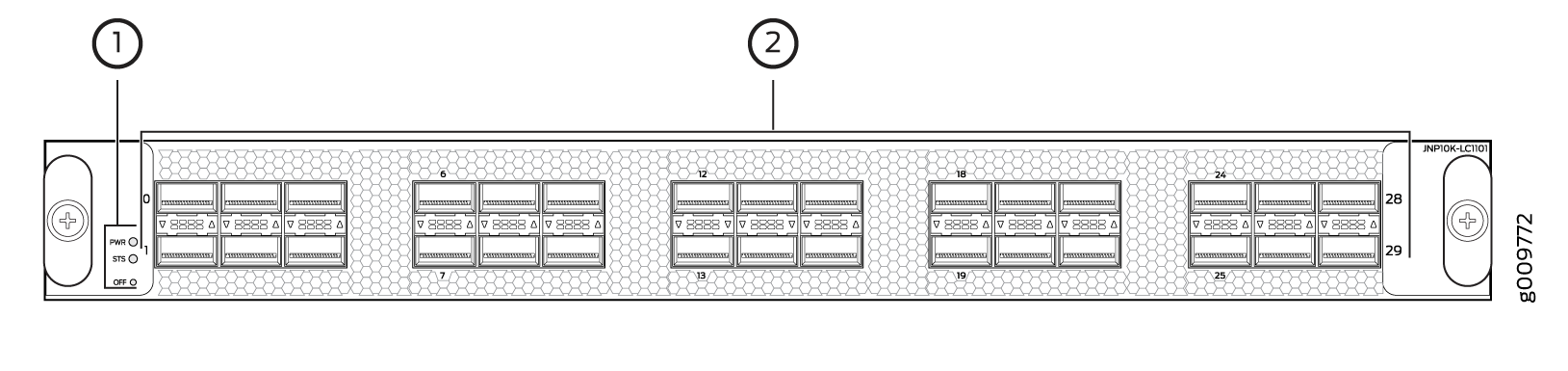
1 — Power LED (PWR), status :LED (STS), and offline/online button (OFF) | 2 — Network ports |
Each network port can operate as a:
-
100GbE port when you use QSFP28 optical transceivers.
-
40GbE port when you use QSFP+ optical transceivers.
To change from the default mode (100GbE) to 40GbE channelized mode, use the Junos OS operational command set chassis fpc slot slot-number pic 0 port port number channelization-speed 10g.
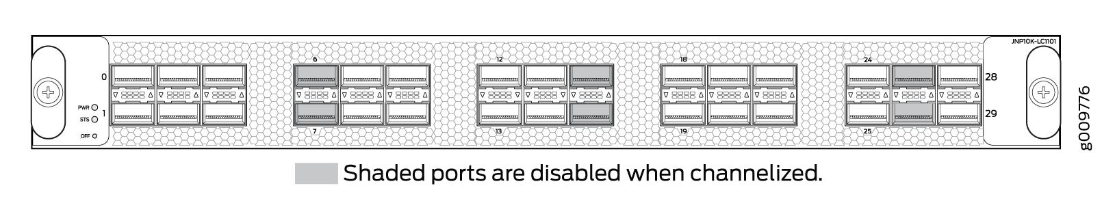
Channelizing 40GbE Ports
You can configure each of the 40GbE ports on the PTX10K-LC1101 line card into four 10GbE channels. When ports are in channelization mode, the fourth port on each Packet Forwarding Engine is disabled, and the remaining four ports that are mapped to the same Packet Forwarding Engine can be used as either 4x10GbE, 40GbE, or 100GbE ports. The channelization mode works independently for each of the Packet Forwarding Engines on the PTX10K-LC1101 line card. See Figure 2 to see which ports are disabled and see Table 4 for the maximum port configurations.
Port Speed |
Nonchannelized Mode (Mode D) |
Channelized Mode (Mode A) |
|---|---|---|
100 Gbps |
30 or |
24 or |
40 Gbps |
30 |
24 or |
10 Gbps |
0 |
96 |
Unlike the PTX10K-LC1102 line card, the PTX10K-LC1101 line card does not have port groups; instead, port behavior is tied to the ASIC associated with the port. To channelize a 40GbE port to 4 independent 10GbE ports, you must configure each port individually. For example, ASIC PE0 maps to ports 0, 2, 4, 6, and 8. The fourth port, port 6, is disabled. See Table 5 for the list of available ports and the associated ASIC mapping in Figure 2 to locate the available and disabled ports.
If you change the channelization mode (mode D to mode A or mode A to mode D), the new port speed
configuration does not cause an FPC to reboot automatically. Instead, it triggers an
FPC need bounce alarm. To ensure that the new port speed configuration takes
effect, you must manually reboot the FPC. The alarm is cleared when you manually reboot the FPC
or delete the new port speed configuration.
When you manually change the port speed from one setting to another, or when the you deactivate
the interface, the show interface interface-name command
shows the error Device interface-name not found for a brief
interval. Ensure that the transceiver is in a working condition. The interface comes up
subsequently.
ASIC |
Available Ports |
Disabled Port |
|---|---|---|
PE0 |
0, 2, 4, 8 |
6 |
PE1 |
1, 3, 5, 9 |
7 |
PE2 |
10, 12, 14, 18 |
16 |
PE3 |
11, 13, 15, 19 |
17 |
PE4 |
20, 22, 24, 28 |
26 |
PE5 |
21, 23, 25, 29 |
27 |
Network Ports
Each of the 30 QSFP28 ports supports:
100GbE using QSFP28 optical transceivers.
40GbE using QSFP+ optical transceivers.
40GbE to 10GbE or 1GbE QSFP-to-SFP adapter (QSA) (Junos OS Release 18.4R1 and later).
PTX10K-LC1102 Line Card
Overview
The PTX10K-LC1102 line card consists of 36 quad small form-factor pluggable plus (QSFP+) ports that support 40GbE optical transceivers. Out of these 36 ports, 12 ports also support 100GbE QSFP28 transceivers. The PTX10K-LC1102 line cards also support 10GbE interfaces. You can channelize 40GbE ports to four independent 10GbE interfaces by configuring the port speed and cabling the port using fiber breakout cables. See Figure 3.
PTX10008 and PTX10016 routers that run Junos OS Release 17.2R1 and later support the PTX10K-LC1102 line card.
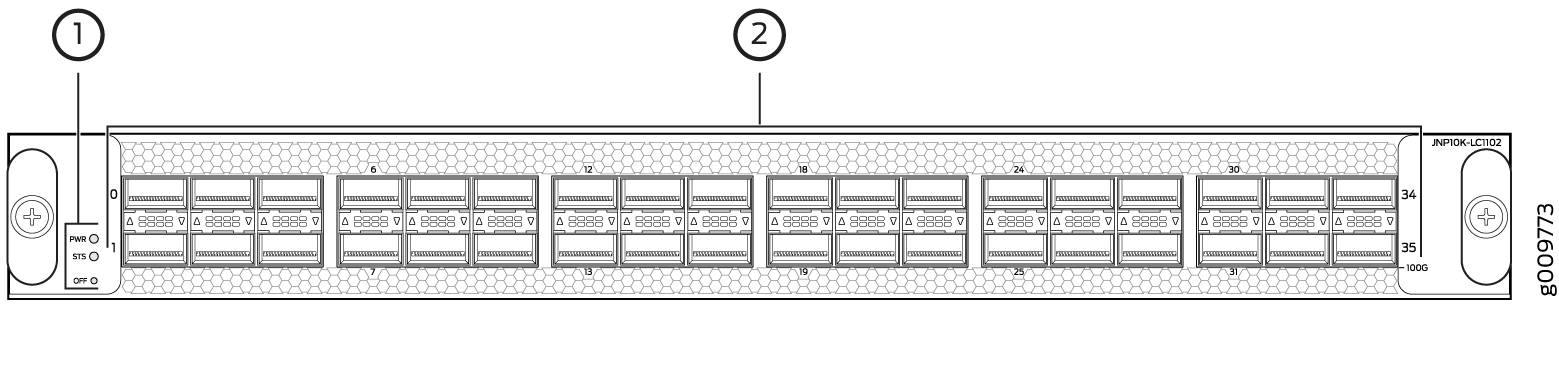
1 — Power LED (PWR), status LED (STS), and offline/online button (OFF) | 2 — Network ports |
You can configure each QSFP28 port as a:
100GbE port using QSFP28 optical transceivers. Only the ports with a fine black line underneath the port support 100GbE. When a QSFP28 transceiver is inserted into such a port and you configure the port for 100GbE, the two adjacent ports are disabled and the QSFP28 port is enabled for 100GbE.
40GbE port using QSFP+ optical transceivers.
10GbE port using breakout cabling and attached optical transceivers. When configured for channelization, the system converts the 40GbE port into four independent 10GbE channels.
Network Ports
Each of the 12 QSFP28 ports supports:
100GbE QSFP28 transceivers
40GbE QSFP+ transceivers
40GbE to 10GbE or 1GbE QSA (Junos OS Release 18.4R1 and later)
Each of the 36 QSFP+ ports supports:
40GbE QSFP+ transceivers
40GbE to 10GbE or 1GbE QSA (Junos OS Release 18.4R1 and later)
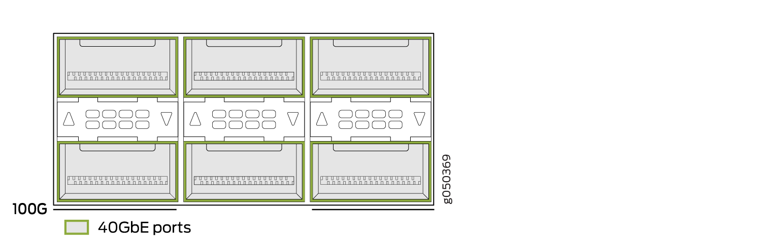
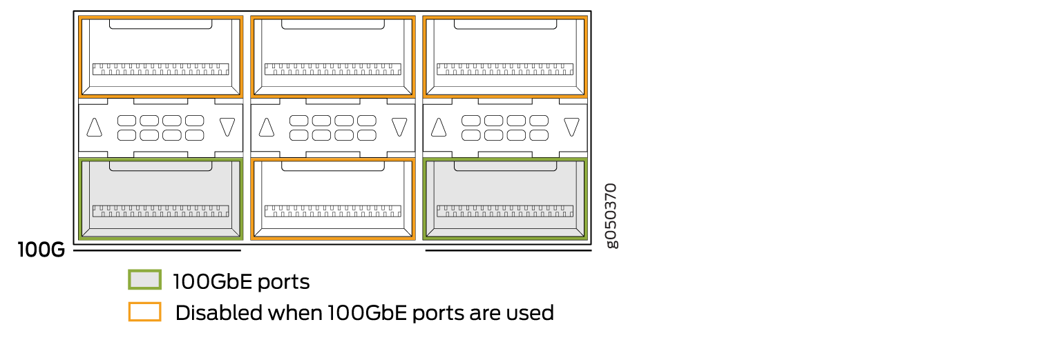
Channelization
Every second and sixth port in a 6xQSFP cage on a PTX10K-LC1102 line card supports 100GbE using QSFP28 transceivers. These 100GbE ports operate either as 100GbE ports or as 40GbE, but are recognized as channelized 4x10GbE by default. See Figure 4 for a closeup view of a 6xQSFP+ cage. When you insert a 40GbE transceiver into a 100GbE port, the port recognizes the 40 Gbps port speed. When you insert a 100GbE transceiver into the port and enable it in the CLI, the port recognizes the 100-Gbps speed and disables two adjacent 40GbE ports. See Figure 5 and Figure 6. You can also use a 100GbE transceiver and run it at 40GbE by using the CLI to set the port speed to 40GbE.
Figure 4 shows the default configuration of a cage of ports on the PTX10K-LC1102.
The 40GbE ports can operate independently, be channelized into four 10GbE ports, or bundled with
the next two consecutive ports and channelized into twelve 10GbE
ports as a port range. Only the first and fourth port in each 6xQSFP
cage are available to channelize a port range (see Figure 7). You must configure the port speed using the set chassis
fpc slot slot-number pic
slot-number port
port-number speed
speed command. For
example, to set the first router port as 40GbE (not channelized),
use the set chassis fpc slot 0 pic
0 port 0 speed
40g command.
Table 6 shows the available combinations for the ports. On the PTX10K-LC1102, the ports are enabled by default.
Port Number |
4x10GbE |
4x10GbE Channelized Port Group |
40GbE |
100GbE |
100GbE Disables |
|---|---|---|---|---|---|
0 |
✓ |
✓ |
✓ |
– |
– |
1 |
✓ |
✓ |
✓ |
0, 2 |
|
2 |
✓ |
✓ |
– |
– |
|
3 |
✓ |
✓ |
✓ |
– |
– |
4 |
✓ |
✓ |
– |
– |
|
5 |
✓ |
✓ |
✓ |
3, 4 |
|
6 |
✓ |
✓ |
✓ |
– |
– |
7 |
✓ |
✓ |
✓ |
6, 8 |
|
8 |
✓ |
✓ |
– |
– |
|
9 |
✓ |
✓ |
✓ |
– |
– |
10 |
✓ |
✓ |
– |
– |
|
11 |
✓ |
✓ |
✓ |
9, 10 |
|
12 |
✓ |
✓ |
✓ |
– |
– |
13 |
✓ |
✓ |
✓ |
12, 14 |
|
14 |
✓ |
✓ |
– |
– |
|
15 |
✓ |
✓ |
✓ |
– |
– |
16 |
✓ |
✓ |
– |
– |
|
17 |
✓ |
✓ |
✓ |
15, 16 |
|
18 |
✓ |
✓ |
✓ |
– |
– |
19 |
✓ |
✓ |
✓ |
18, 20 |
|
20 |
✓ |
✓ |
– |
– |
|
21 |
✓ |
✓ |
✓ |
– |
– |
22 |
✓ |
✓ |
– |
– |
|
23 |
✓ |
✓ |
✓ |
21, 22 |
|
24 |
✓ |
✓ |
✓ |
– |
– |
25 |
✓ |
✓ |
✓ |
24, 26 |
|
26 |
✓ |
✓ |
– |
– |
|
27 |
✓ |
✓ |
✓ |
– |
– |
28 |
✓ |
✓ |
– |
– |
|
29 |
✓ |
✓ |
✓ |
27, 28 |
|
30 |
✓ |
✓ |
✓ |
– |
– |
31 |
✓ |
✓ |
✓ |
30, 32 |
|
32 |
✓ |
✓ |
– |
– |
|
33 |
✓ |
✓ |
✓ |
– |
– |
34 |
✓ |
✓ |
– |
– |
|
35 |
✓ |
✓ |
✓ |
33, 34 |
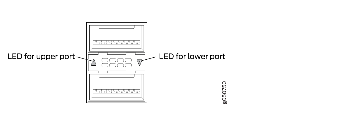
Port Status and Activity LEDs
Each network port has a bicolored up or down LED indicator that shows port status and link activity based on whether or not the port is configured for channelization. See Figure 8, Table 7, and Table 8.
Color |
State |
Description |
|---|---|---|
Unlit |
Off |
The port is administratively disabled, there is no power, the link is down, or a transceiver is not present. |
Green |
On steadily |
A link is established but there is no activity. |
Blinking |
A link is up and there is activity. |
|
Yellow or Amber |
Slow blink or blip |
The beacon function was enabled on the port. |
Blinking |
A single LED blinking indicates an interface fault. |
Color |
State |
Description |
|---|---|---|
Unlit |
Off |
The port is administratively disabled, there is no power, the link is down, or a transceiver is not present. All sub-channels are disabled. |
Green |
On steadily |
A link is established. When channelized, all sub-channels are up. When not channelized, it indicates no activity. |
Blinking |
A link is up and there is activity. When not channelized, it indicates the port is up and active in either 40GbE or 100GbE mode. When channelized, all four channels are up and active. |
|
Yellow or Amber (channelized) |
On steadily |
At least one channel link is up, but not all channels are up. There is no activity on the channel link. |
Flashing |
At least one channel link is up, but not all channels are up. There is activity on the channel link. |
|
Slow blink, or blip |
The beacon function is enabled on one or more sub-channels. |
|
Blinking |
One or more sub-channels has a fault condition. |
|
Yellow or Amber |
Blinking |
A single LED blinking indicates an interface fault. All four LEDs blink to indicate the beacon function was enabled on the port. |
PTX10K-LC1104 Line Card
- Hardware Features
- Compatibility
- Optical Transmit Specifications
- Optical Receive Specifications
- Status and Activity LEDs
- Optical and Ethernet Interface Alarms and Defects
Hardware Features
The PTX10K-LC1104 line card provides up to 1.2 Tbps of packet forwarding for cloud providers, service providers, and enterprises that need coherent dense wavelength-division multiplexing (DWDM) with Media Access Control Security (MACsec) features. The 6-port line card, with built-in optics, supports flexible rate modulation at 100-Gbps, 150-Gbps, and 200-Gbps speeds. The PTX10008 and PTX10016 routers support a maximum of four PTX10K-LC1104 coherent line cardss. See Figure 9.
PTX10008 routers that run Junos OS Release 17.4R1-S1 and later support the PTX10K-LC1104 line card. PTX10016 routers that run Junos OS Release 18.3R1 and later support the PTX10K-LC1104 line card.
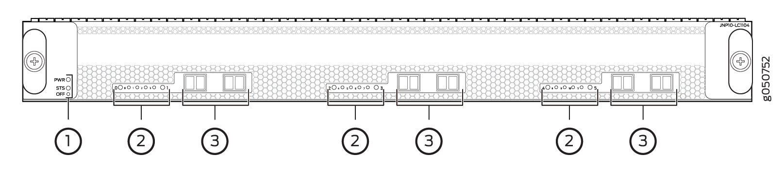
1 — Power LED (PWR), status LED (STS), and offline/online button (OFF) | 3 — Ports with embedded optics |
2 — Network link and Ethernet link LEDs |
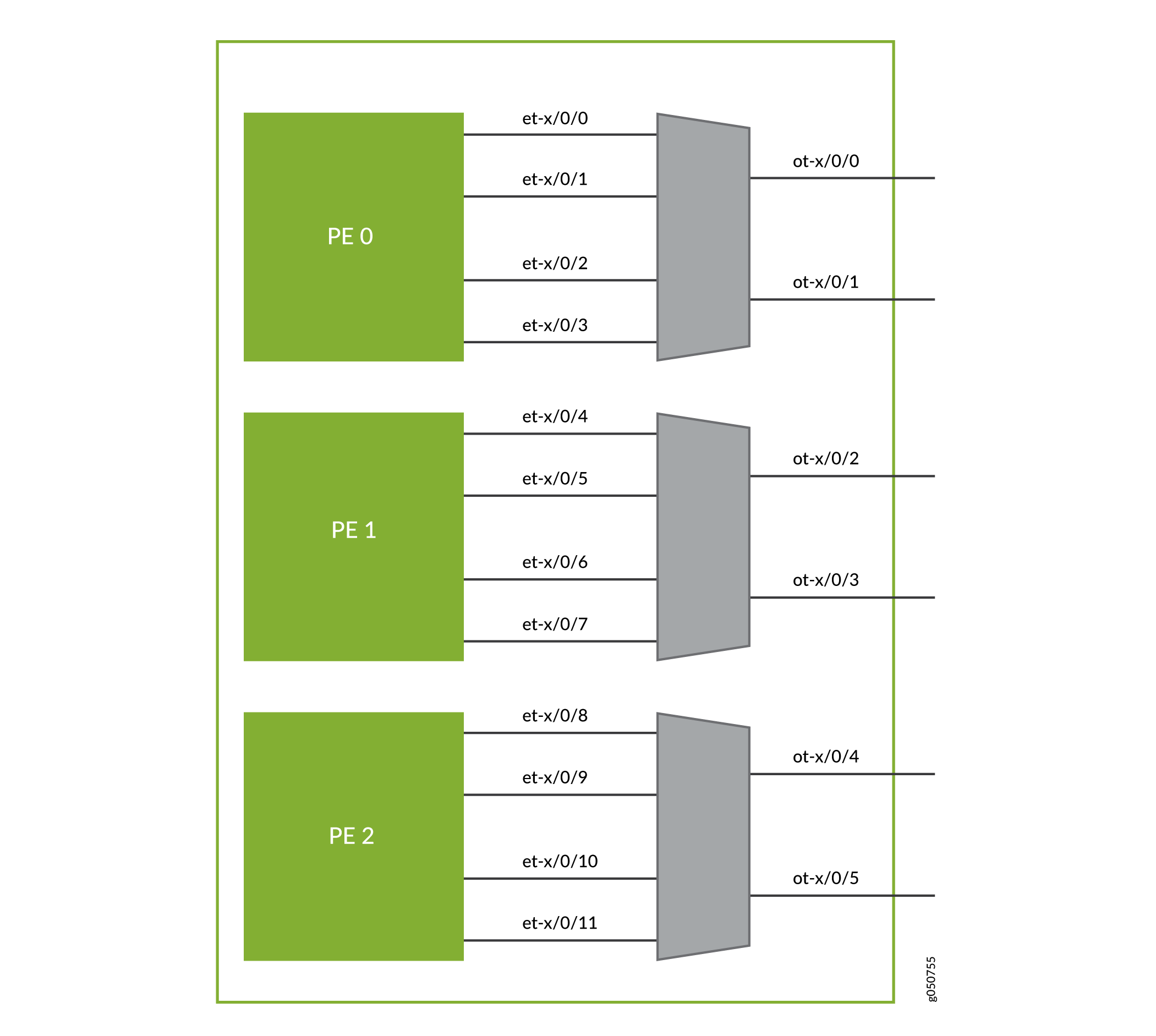
Each PTX10K-LC1104 has six physical interfaces (ot-x/x/x) that connect to one of three built-in flexible rate optical transponders for a maximum of 24 physical interfaces on a PTX10008 or PTX10016 system. Each transponder connects four 100GbE logical interfaces (et-x/x/x) to one of three forwarding ASICs. These forwarding ASICs are responsible for optional MACsec encryption on each 100GbE interface. See Figure 10.
All optical properties are configured under the ot interface. Use the
set interfaces ot-x/x/x
optics-options CLI command to set these options. Perform MACsec
configuration on the et interface using the set
security macsec connectivity-association ca-name
encryption-algorithm. Optical transport network (OTN)-related
configurations are also done on the et- interface.
Each of the six network ports can operate in one of three modulation formats; see Table 9.
Speed (Gbps) |
Modulation |
Distance |
|---|---|---|
100 |
DP-QPSK |
long haul–4000 km |
150 |
DP-8QAM |
regional or metro–2000 km |
200 |
DP-16QAM |
metro DCI–1000 km |
Compatibility
The Juniper Networks integrated DWDM solution includes integrated 100GbE coherent optics on Juniper Networks QFX Series Switches, MX Series 5G Universal Routing Platforms, PTX Series Packet Transport Routers, and Juniper Networks® BTI Series Packet Optical Platforms optimized for Data Center Interconnect (DCI). As part of the Open Cloud Interconnect (OCI) solution, the PTX10K-LC1104 coherent line card is compatible with many third-party optical products as well as Juniper Networks optical solutions and offerings. The line card is interoperable with the BTI Series Packet Optical Transport UFM6 in 100-Gbps and 200-Gbps modes. It is also compatible with the MX Series MICs and PTX Series PICs in 100-Gbps mode. See Table 10.
Platform |
Product |
Model Information |
|---|---|---|
PTX Series |
PTX-5-100-WDM |
See the Hardware Compatibility Tool, PTX-5-100-WDM. |
MX Series |
MIC3-100G-DWDM |
See the Hardware Compatibility Tool, MIC3-100G-DWDM. |
QFX Series |
QFX10K-12C-DWDM |
See the Hardware Compatibility Tool, QFX10K-12C-DWDM. |
Optical Transmit Specifications
You can connect the line card using single-mode fiber-optic (SMF) and LC connectors. See Table 11 and Table 12 for the optical transponder specifications.
Specification |
Value |
|---|---|
Standards compliance |
IEEE 802.3 IEC 60825-1 Class 1 |
Modulation format |
DP-QPSK, DP-8QAM, DP-16QAM |
Line rate |
DP-QPSK = 136.66 Gbps DP-8QAM = 205 Gbps DP-16QAM= 273.33 Gbps |
FEC types |
15% or 25% SD-FEC |
Channel-plan wavelength range |
Extended C-band, 1528.77 nm to 1566.72 nm |
Channel-plan frequency range |
196.1 THz to 191.35 THz |
Channel spacing |
37.5 GHz, 50 GHz, and 100 GHz |
Channel tunability |
12.5 GHz grid. See 1.2-Terabyte Per Second DWDM OTN Module Wavelengths. |
Optical transmitter output power (on) |
–12 to 1.5 dBm, 0.1 dB steps, +/–-1 dB accuracy |
Optical transmitter output power (off) |
≤ —40 dBM |
Optical transmitter wavelength accuracy |
+/-–1.8 GHz |
Optical transmitter channel tuning time |
≤ 90 seconds across C-band |
TX output optical signal-to-noise ratio (OSNR) |
≥ 36 dB |
Optical Receive Specifications
Specification |
100G DP-PSK |
150G DP-8QAM |
200G DP-16QAM |
|---|---|---|---|
Optical receiver input power range (low Rx OSNR) |
—18 dBm to 0 dBm |
—18 dBm to 0 dBm |
—18 dBm to 0 dBm |
Optical receiver input power range (unamplified/dark fiber applications) |
—32 dBm to 0 dBm |
—27 dBm to 0 dBm |
—25 dBm to 0 dBm |
Optical receiver damage input power threshold |
+17 dBm |
+17 dBm |
+17 dBm |
Optical receiver minimum OSNR (back-to-back), typical |
10.3 dB |
14.7 dB |
17.6 dB |
Optical receiver minimum OSNR (back-to-back), worst-case, EOL |
11.5 dB |
16.0 dB |
19.0 dB |
Optical receiver chromatic dispersion tolerance |
+/— 70,000 ps/nm |
+/— 45,000 ps/nm |
+/—30,000 ps/nm |
Optical receiver PMD tolerance |
30 ps mean DGD |
20 ps mean DGD |
15 ps mean DGD |
Optical receiver polarization tracking |
100 krad/s |
50 krad/s |
50 krad/s |
Status and Activity LEDs
There are two types of LEDs for the network ports: port LEDs and Ethernet link LEDs. The LEDs for the six physical ports indicate the link state of an ot- interface. There are four LEDs between each port pair that indicate the link state of the associated et- interfaces, (see Figure 11). To determine the link state of the ot- interface, see Table 13.
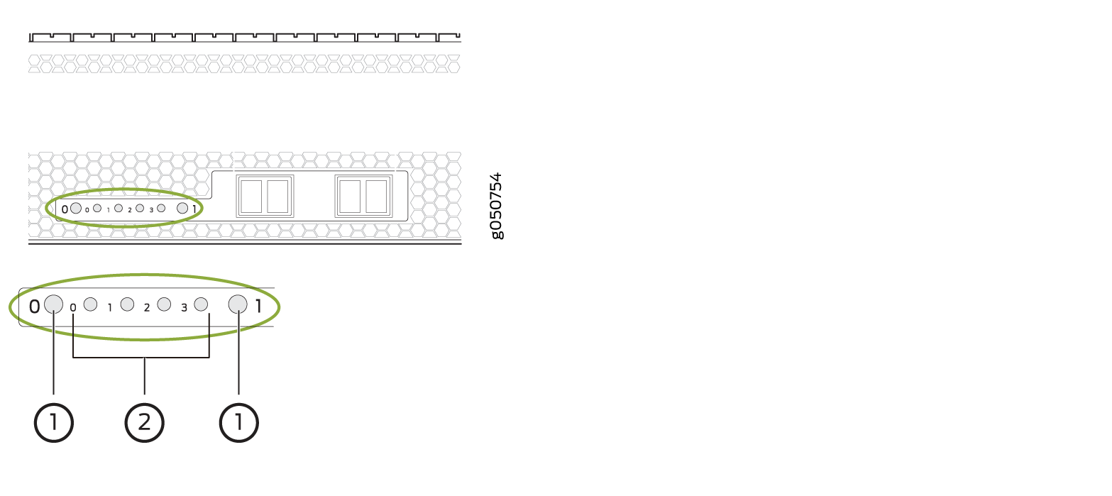
1 — Port LEDs (ot- interfaces) | 2 — Ethernet LEDs (et- link interfaces) |
Color |
Description |
|---|---|
Unlit |
The port is not configured. |
Solid green |
A link is established on the |
Solid amber |
The optical module associated with the port has a fault condition, or the port is configured but the link is down. |
You can also determine the configuration of the et interfaces by examining the pattern of the four Ethernet LEDs. See Table 14. To determine the link
status and of those et interfaces, see Table 15.
Modulation Format |
Aggregate Data Rate |
|
|
Configuration |
|
|---|---|---|---|---|---|
Ports 0, 2, 4 |
1, 3, 5 |
||||
16-QAM (x2) |
4 x 100GbE |
200 Gbps |
200 Gbps |
0, 1, 2, 3 |
2 independent 200 Gbps 16-QAM |
QPSK and 16-QAM |
3 x 100GbE |
100 Gbps |
200 Gbps |
0, 2, 3 |
Independent QPSK and 16-QAM |
16-QAM and QPSK |
3 x 100GbE |
200 Gbps |
100 Gbps |
0, 1, 2 |
Independent QPSK and 16-QAM |
8-QAM |
3 x 100GbE |
150 Gbps |
150 Gbps |
0, 1, 2 |
2 Coupled 150 Gbps 8-QAM |
QPSK and QPSK |
2 x 100GbE |
100 Gbps |
100 Gbps |
0,2 |
Independent 100 Gbps QPSK |
Color |
Description |
|---|---|
Unlit |
The et- interface is down. |
Solid green |
The et- interface is up, but there is no activity. |
Blinking green |
The link is up on the et- interface, and there is activity. |
Optical and Ethernet Interface Alarms and Defects
Table 16 and Table 17 describe the ot and et interface alarms and defects that can occur on the line card and the link status when the alarm or defect occurs.
You can view optical and Ethernet alarms and defects by using
the show interfaces interface-name extensive operational-mode CLI command.
Category |
Alarm |
Description |
Link Status |
|---|---|---|---|
OTN |
Network lane LOS |
Loss of signal |
Link down |
Network lane LOF |
Loss of frame |
Link down |
|
Network lane LOM |
Loss of multiframe |
Link down |
|
Network lane OTU-BDI |
Backward defect identification |
Link down |
|
OTN FEC |
FEC degrade (OTU-FEC-DEG) |
Forward error correction degraded |
Link down if signal degrade or backward FRR thresholds are met |
FEC excessive (OTU-FEC-EXE) |
There are uncorrected words and there are errors in the frame header. |
Possible link down |
|
Optics and Optical Channel |
Module fault |
Module fault state |
Link down |
Rx modem synch fault |
Modem sync detect fault |
Link down |
|
Rx modem loss of lock OTU-BDI |
Modem lock fault |
Link down |
|
Rx loss of alignment |
Loss of alignment fault |
Link down |
|
Network lane LOS |
Lane Rx loss of signal |
Alarm |
|
Modulator bias control loop fail |
Modulator bias control loop failed to converge. |
Alarm |
|
ITLA fault |
ITLA operation failure |
Alarm |
|
DAC calibration fault |
DAC calibration fault |
Alarm |
|
ADC calibration fault |
ACD calibration fault |
Alarm |
Category |
Alarm |
Description |
Link Status |
|---|---|---|---|
OTN |
LOS |
Loss of signal |
Alarm |
LOF |
Loss of frame |
Alarm |
|
LOM |
Loss of multiframe |
Alarm |
|
OTN OTU |
OTU-AIS |
Alarm indication signal or all ones signal |
Alarm |
OTU-BDI |
Backward defect identification |
Alarm |
|
OTU-IAE |
Incoming alignment error |
Warning |
|
OTU-TTIM |
Destination access point identifier (DAPI), source access point identifier (SAPI), or both mismatch from expected to received |
Warning |
|
OTU-BIAE |
Backward incoming alignment error |
Warning |
|
OTU-TSF |
OTU trail signal fail |
Warning |
|
OTU-SSF |
OTU server signal fail |
Warning |
|
OTN ODU |
ODU-AIS |
Alarm indication signal or all one signal |
Alarm |
ODU-OCI |
Open connection error |
Alarm |
|
ODU-LCK |
ODU lock triggers for path monitoring and TCM levels 1 through 6 |
Alarm |
|
ODU-BDI |
Backward defect indication |
Alarm |
|
ODU-TTIM |
DAPI or SAPI mismatch from expected to received |
Warning |
|
ODU-IAE |
Incoming alignment error |
Warning |
|
ODU-LTC |
Loss of tandem connection |
Warning |
|
ODU-CSF |
Client signal failure |
Warning |
|
ODU-TSF |
Trail signal failure |
Warning |
|
ODU-SSF |
Server signal failure |
Warning |
|
ODU-PTIM |
Payload type mismatch |
Alarm |
See Also
1.2-Terabyte Per Second DWDM OTN Module Wavelengths
The PTX10K-LC1104 coherent line card and the QFX10000-12C-DWDM line card provide six 200-Gbps coherent MACsec ports with built-in long-reach optics. DWDM channel frequency offsets are 0.02 THz. The QFX10000-12C-DWDM line card is available for the QFX10008 and QFX10016 switch chassis running Junos OS Release 17.3R1 and later. The PTX10K-LC1104 coherent line card is available for the PTX10008 and PTX10016 routers. See Table 18 for the available channel frequencies and wavelengths.
Frequency (THz) |
Wavelength (nm) |
Offset (GHz) |
|---|---|---|
191.35 |
1566.72 |
12.5/50 |
191.36 |
1566.62 |
12.5 |
191.38 |
1566.52 |
12.5 |
191.39 |
1566.42 |
12.5 |
191.4 |
1566.31 |
12.5/50/100 |
191.41 |
1566.21 |
12.5 |
191.43 |
1566.11 |
12.5 |
191.44 |
1566.01 |
12.5 |
191.45 |
1565.91 |
12.5/50 |
191.46 |
1565.8 |
12.5 |
191.48 |
1565.7 |
12.5 |
191.49 |
1565.6 |
12.5 |
191.5 |
1565.5 |
12.5/50/100 |
191.51 |
1565.39 |
12.5 |
191.53 |
1565.29 |
12.5 |
191.54 |
1565.19 |
12.5 |
191.55 |
1565.09 |
12.5/50 |
191.56 |
1564.99 |
12.5 |
191.58 |
1564.88 |
12.5 |
191.59 |
1564.78 |
12.5 |
191.6 |
1564.68 |
12.5/50/100 |
191.61 |
1564.58 |
12.5 |
191.63 |
1564.48 |
12.5 |
191.64 |
1564.37 |
12.5 |
191.65 |
1564.27 |
12.5/50 |
191.66 |
1564.17 |
12.5 |
191.68 |
1564.07 |
12.5 |
191.69 |
1563.97 |
12.5 |
191.7 |
1563.86 |
12.5/50/100 |
191.71 |
1563.76 |
12.5 |
191.73 |
1563.66 |
12.5 |
191.74 |
1563.56 |
12.5 |
191.75 |
1563.46 |
12.5/50 |
191.76 |
1563.35 |
12.5 |
191.78 |
1563.25 |
12.5 |
191.79 |
1563.15 |
12.5 |
191.8 |
1563.05 |
12.5/50/100 |
191.81 |
1562.95 |
12.5 |
191.83 |
1562.84 |
12.5 |
191.84 |
1562.74 |
12.5 |
191.85 |
1562.64 |
12.5/50 |
191.86 |
1562.54 |
12.5 |
191.88 |
1562.44 |
12.5 |
191.89 |
1562.33 |
12.5 |
191.9 |
1562.23 |
12.5/50/100 |
191.91 |
1562.13 |
12.5 |
191.93 |
1562.03 |
12.5 |
191.94 |
1561.93 |
12.5 |
191.95 |
1561.83 |
12.5/50 |
191.96 |
1561.72 |
12.5 |
191.98 |
1561.62 |
12.5 |
191.99 |
1561.52 |
12.5 |
192 |
1561.42 |
12.5/50/100 |
192.01 |
1561.32 |
12.5 |
192.03 |
1561.22 |
12.5 |
192.04 |
1561.11 |
12.5 |
192.05 |
1561.01 |
12.5/50 |
192.06 |
1560.91 |
12.5 |
192.08 |
1560.81 |
12.5 |
192.09 |
1560.71 |
12.5 |
192.1 |
1560.61 |
12.5/50/100 |
192.11 |
1560.51 |
12.5 |
192.13 |
1560.4 |
12.5 |
192.14 |
1560.3 |
12.5 |
192.15 |
1560.2 |
12.5/50 |
192.16 |
1560.1 |
12.5 |
192.18 |
1560 |
12.5 |
192.188 |
1559.9 |
12.5 |
192.2 |
1559.79 |
12.5/50/100 |
192.21 |
1559.69 |
12.5 |
192.23 |
1559.59 |
12.5 |
192.24 |
1559.49 |
12.5 |
192.25 |
1559.39 |
12.5/50 |
192.26 |
1559.29 |
12.5 |
192.28 |
1559.19 |
12.5 |
192.29 |
1559.08 |
12.5 |
192.3 |
1558.98 |
12.5/50/100 |
192.31 |
1558.88 |
12.5 |
192.33 |
1558.78 |
12.5 |
192.34 |
1558.68 |
12.5 |
192.35 |
1558.58 |
12.5/50 |
192.36 |
1558.48 |
12.5 |
192.38 |
1558.38 |
12.5 |
192.39 |
1558.27 |
12.5 |
192.4 |
1558.17 |
12.5/50/100 |
192.41 |
1558.07 |
12.5 |
192.43 |
1557.97 |
12.5 |
192.44 |
1557.87 |
12.5 |
192.45 |
1557.77 |
12.5/50 |
192.46 |
1557.67 |
12.5 |
192.48 |
1557.57 |
12.5 |
192.49 |
1557.47 |
12.5 |
192.5 |
1557.36 |
12.5/50/100 |
192.51 |
1557.26 |
12.5 |
192.53 |
1557.16 |
12.5 |
192.54 |
1557.06 |
12.5 |
192.55 |
1556.96 |
12.5/50 |
192.56 |
1556.86 |
12.5 |
192.58 |
1556.76 |
12.5 |
192.59 |
1556.66 |
12.5 |
192.6 |
1556.56 |
12.5/50/100 |
192.61 |
1556.45 |
12.5 |
192.63 |
1556.35 |
12.5 |
192.64 |
1556.25 |
12.5 |
192.65 |
1556.15 |
12.5/50 |
192.66 |
1556.05 |
12.5 |
192.68 |
1555.95 |
12.5 |
192.69 |
1555.85 |
12.5 |
192.7 |
1555.75 |
12.5/50/100 |
192.71 |
1555.65 |
12.5 |
192.73 |
1555.55 |
12.5 |
192.74 |
1555.44 |
12.5 |
192.75 |
1555.34 |
12.5/50 |
192.76 |
1555.24 |
12.5 |
192.78 |
1555.14 |
12.5 |
192.79 |
1555.04 |
12.5 |
192.8 |
1554.94 |
12.5/50/100 |
192.81 |
1554.84 |
12.5 |
192.83 |
1554.74 |
12.5 |
192.84 |
1554.64 |
12.5 |
192.85 |
1554.54 |
12.5/50 |
192.86 |
1554.44 |
12.5 |
192.88 |
1554.34 |
12.5 |
192.89 |
1554.24 |
12.5 |
192.9 |
1554.13 |
1554.134 |
192.91 |
1554.03 |
12.5 |
192.93 |
1553.93 |
12.5 |
192.94 |
1553.83 |
12.5 |
192.95 |
1553.73 |
12.5/50 |
192.96 |
1553.63 |
12.5 |
192.98 |
1553.53 |
12.5 |
192.99 |
1553.43 |
12.5 |
193 |
1553.33 |
12.5/50/100 |
193.01 |
1553.23 |
12.5 |
193.03 |
1553.13 |
12.5 |
193.04 |
1553.03 |
12.5 |
193.05 |
1552.93 |
12.5/50 |
193.06 |
1552.83 |
12.5 |
193.08 |
1552.73 |
12.5 |
193.09 |
1552.63 |
12.5 |
193.1 |
1552.52 |
12.5/50/100 |
193.11 |
1552.42 |
12.5 |
193.13 |
1552.32 |
12.5 |
193.14 |
1552.22 |
12.5 |
193.15 |
1552.12 |
12.5/50 |
193.16 |
1552.02 |
12.5 |
193.18 |
1551.92 |
12.5 |
193.19 |
1551.82 |
12.5 |
193.2 |
1551.72 |
12.5/50/100 |
193.21 |
1551.62 |
12.5 |
193.23 |
1551.52 |
12.5 |
193.24 |
1551.42 |
12.5 |
193.25 |
1551.32 |
12.5/50 |
193.26 |
1551.22 |
12.5 |
193.28 |
1551.12 |
12.5 |
193.29 |
1551.02 |
12.5 |
193.3 |
1550.92 |
12.5/50/100 |
193.31 |
1550.82 |
12.5 |
193.33 |
1550.72 |
12.5 |
193.34 |
1550.62 |
12.5 |
193.35 |
1550.52 |
12.5/50 |
193.36 |
1550.42 |
12.5 |
193.38 |
1550.32 |
12.5 |
193.39 |
1550.22 |
12.5 |
193.4 |
1550.12 |
12.5/50/100 |
193.41 |
1550.02 |
12.5 |
193.43 |
1549.92 |
12.5 |
193.44 |
1549.82 |
12.5 |
193.45 |
1549.72 |
12.5/50 |
193.46 |
1549.62 |
12.5 |
193.48 |
1549.52 |
12.5 |
193.49 |
1549.42 |
12.5 |
193.5 |
1549.32 |
12.5/50/100 |
193.51 |
1549.22 |
12.5 |
193.53 |
1549.12 |
12.5 |
193.54 |
1549.02 |
12.5 |
193.55 |
1548.92 |
12.5/50 |
193.56 |
1548.82 |
12.5 |
193.58 |
1548.72 |
12.5 |
193.59 |
1548.62 |
12.5 |
193.6 |
1548.52 |
12.5/50/100 |
193.61 |
1548.42 |
12.5 |
193.63 |
1548.32 |
12.5 |
193.64 |
1548.22 |
12.5 |
193.65 |
1548.12 |
12.5/50 |
193.66 |
1548.02 |
12.5 |
193.68 |
1547.92 |
12.5 |
193.69 |
1547.82 |
12.5 |
193.7 |
1547.72 |
12.5/50/100 |
193.71 |
1547.62 |
12.5 |
193.73 |
1547.52 |
12.5 |
193.74 |
1547.42 |
12.5 |
193.75 |
1547.32 |
12.5/50 |
193.76 |
1547.22 |
12.5 |
193.78 |
1547.12 |
12.5 |
193.79 |
1547.02 |
12.5 |
193.8 |
1546.92 |
12.5/50/100 |
193.81 |
1546.82 |
12.5 |
193.83 |
1546.72 |
12.5 |
193.84 |
1546.62 |
12.5 |
193.85 |
1546.52 |
12.5/50 |
193.86 |
1546.42 |
12.5 |
193.88 |
1546.32 |
12.5 |
193.89 |
1546.22 |
12.5 |
193.9 |
1546.12 |
12.5/50/100 |
193.91 |
1546.02 |
12.5 |
193.93 |
1545.92 |
12.5 |
193.94 |
1545.82 |
12.5 |
193.95 |
1545.72 |
12.5/50 |
193.96 |
1545.62 |
12.5 |
193.98 |
1545.52 |
12.5 |
193.99 |
1545.42 |
12.5 |
194 |
1545.32 |
12.5/50/100 |
194.01 |
1545.22 |
12.5 |
194.03 |
1545.12 |
12.5 |
194.04 |
1545.02 |
12.5 |
194.05 |
1544.92 |
12.5/50 |
194.06 |
1544.82 |
12.5 |
194.08 |
1544.73 |
12.5 |
194.09 |
1544.63 |
12.5 |
194.1 |
1544.53 |
12.5/50/100 |
194.11 |
1544.43 |
12.5 |
194.13 |
1544.33 |
12.5 |
194.14 |
1544.23 |
12.5 |
194.15 |
1544.13 |
12.5/50 |
194.16 |
1544.03 |
12.5 |
194.18 |
1543.93 |
12.5 |
194.19 |
1543.83 |
12.5 |
194.2 |
1543.73 |
12.5/50/100 |
194.21 |
1543.63 |
12.5 |
194.23 |
1543.53 |
12.5 |
194.24 |
1543.43 |
12.5 |
194.25 |
1543.33 |
12.5/50 |
194.26 |
1543.23 |
12.5 |
194.28 |
1543.14 |
12.5 |
194.29 |
1543.04 |
12.5 |
194.3 |
1542.94 |
12.5/50/100 |
194.31 |
1542.84 |
12.5 |
194.33 |
1542.74 |
12.5 |
194.34 |
1542.64 |
12.5 |
194.35 |
1542.54 |
12.5/50 |
194.36 |
1542.44 |
12.5 |
194.38 |
1542.34 |
12.5 |
194.39 |
1542.24 |
12.5 |
194.4 |
1542.14 |
12.5/50/100 |
194.41 |
1542.04 |
12.5 |
194.43 |
1541.94 |
12.5 |
194.44 |
1541.85 |
12.5 |
194.45 |
1541.75 |
12.5/50 |
194.46 |
1541.65 |
12.5 |
194.48 |
1541.55 |
12.5 |
194.49 |
1541.45 |
12.5 |
194.5 |
1541.35 |
12.5/50/100 |
194.51 |
1541.25 |
12.5 |
194.53 |
1541.15 |
12.5 |
194.54 |
1541.05 |
12.5 |
194.55 |
1540.95 |
12.5/50 |
194.56 |
1540.85 |
12.5 |
194.58 |
1540.76 |
12.5 |
194.59 |
1540.66 |
12.5 |
194.6 |
1540.56 |
12.5/50/100 |
194.61 |
1540.46 |
12.5 |
194.63 |
1540.36 |
12.5 |
194.64 |
1540.26 |
12.5 |
194.65 |
1540.16 |
12.5/50 |
194.66 |
1540.06 |
12.5 |
194.68 |
1539.96 |
12.5 |
194.69 |
1539.87 |
12.5 |
194.7 |
1539.77 |
12.5/50/100 |
194.71 |
1539.67 |
12.5 |
194.73 |
1539.57 |
12.5 |
194.74 |
1539.47 |
12.5 |
194.75 |
1539.37 |
12.5/50 |
194.76 |
1539.27 |
12.5 |
194.78 |
1539.17 |
12.5 |
194.79 |
1539.07 |
12.5 |
194.8 |
1538.98 |
12.5/50/100 |
194.81 |
1538.88 |
12.5 |
194.83 |
1538.78 |
12.5 |
194.84 |
1538.68 |
12.5 |
194.85 |
1538.58 |
12.5/50 |
194.86 |
1538.48 |
12.5 |
194.88 |
1538.38 |
12.5 |
194.89 |
1538.29 |
12.5 |
194.9 |
1538.19 |
12.5/50/100 |
194.91 |
1538.09 |
12.5 |
194.93 |
1537.99 |
12.5 |
194.94 |
1537.89 |
12.5 |
194.95 |
1537.79 |
12.5/50 |
194.96 |
1537.69 |
12.5 |
194.98 |
1537.59 |
12.5 |
194.99 |
1537.5 |
12.5 |
195 |
1537.4 |
12.5/50/100 |
195.01 |
1537.3 |
12.5 |
195.03 |
1537.2 |
12.5 |
195.04 |
1537.1 |
12.5 |
195.05 |
1537 |
12.5/50 |
195.06 |
1536.9 |
12.5 |
195.08 |
1536.8 |
12.5 |
195.09 |
1536.7 |
12.5 |
195.1 |
1536.6 |
12.5/50/100 |
195.11 |
1536.51 |
12.5 |
195.13 |
1536.41 |
12.5 |
195.14 |
1536.31 |
12.5 |
195.15 |
1536.22 |
12.5/50 |
195.16 |
1536.12 |
12.5 |
195.18 |
1536.02 |
12.5 |
195.19 |
1535.92 |
12.5 |
195.2 |
1535.82 |
12.5/50/100 |
195.21 |
1535.72 |
12.5 |
195.23 |
1535.63 |
12.5 |
195.24 |
1535.53 |
12.5 |
195.25 |
1535.43 |
12.5/50 |
195.26 |
1535.33 |
12.5 |
195.28 |
1535.23 |
12.5 |
195.29 |
1535.13 |
12.5 |
195.3 |
1535.03 |
12.5/50/100 |
195.31 |
1534.94 |
12.5 |
195.33 |
1534.84 |
12.5 |
195.34 |
1534.74 |
12.5 |
195.35 |
1564.64 |
12.5/50 |
195.36 |
1534.55 |
12.5 |
195.38 |
1534.45 |
12.5 |
195.39 |
1534.35 |
12.5 |
195.4 |
1534.25 |
12.5/50/100 |
195.41 |
1534.15 |
12.5 |
195.43 |
1534.05 |
12.5 |
195.44 |
1533.96 |
12.5 |
195.45 |
1533.86 |
12.5/50 |
195.46 |
1533.76 |
12.5 |
195.48 |
1533.66 |
12.5 |
195.49 |
1533.56 |
12.5 |
195.5 |
1533.47 |
12.5/50/100 |
195.51 |
1533.37 |
12.5 |
195.53 |
1533.27 |
12.5 |
195.54 |
1533.17 |
12.5 |
195.55 |
1533.07 |
12.5/50 |
195.56 |
1532.98 |
12.5 |
195.58 |
1532.88 |
12.5 |
195.59 |
1532.78 |
12.5 |
195.6 |
1532.68 |
12.5/50/100 |
195.61 |
1532.58 |
12.5 |
195.63 |
1532.49 |
12.5 |
195.64 |
1532.39 |
12.5 |
195.65 |
1532.29 |
12.5/50 |
195.66 |
1532.19 |
12.5 |
195.68 |
1532.09 |
12.5 |
195.69 |
1532 |
12.5 |
195.7 |
1531.9 |
12.5/50/100 |
195.71 |
1531.8 |
12.5 |
195.73 |
1531.7 |
12.5 |
195.74 |
1531.61 |
12.5 |
185.75 |
1531.51 |
12.5/50 |
185.76 |
1531.41 |
12.5 |
195.78 |
1531.31 |
12.5 |
195.79 |
1531.21 |
12.5 |
195.8 |
1531.12 |
12.5/50/100 |
195.81 |
1531.02 |
12.5 |
195.83 |
1530.92 |
12.5 |
195.84 |
1530.82 |
12.5 |
195.85 |
1530.73 |
12.5/50 |
195.86 |
1530.63 |
12.5 |
195.88 |
1530.53 |
12.5 |
195.89 |
1530.43 |
12.5 |
195.9 |
1530.33 |
12.5/50/100 |
195.91 |
1530.34 |
12.5 |
195.93 |
1530.24 |
12.5 |
195.94 |
1530.04 |
12.5 |
195.95 |
1529.94 |
12.5/50 |
195.96 |
1529.85 |
12.5 |
195.98 |
1529.75 |
12.5 |
195.99 |
1529.65 |
12.5 |
196 |
1529.55 |
12.5/50/100 |
196.01 |
1529.46 |
12.5 |
196.03 |
1529.36 |
12.5 |
196.04 |
1529.26 |
12.5 |
196.05 |
1529.16 |
12.5/50 |
196.06 |
1529.07 |
12.5 |
196.08 |
1528.97 |
12.5 |
196.09 |
1528.87 |
12.5 |
196.1 |
1528.77 |
12.5/50/100 |
PTX10K-LC1105 Line Card
- Overview
- Network Ports
- Channelizing 40-Gigabit Ethernet Ports
- Power and Status LEDs
- Port Status and Activity LEDs
Overview
The PTX10K-LC1105 line card is designed to provide secure Ethernet communication across high-speed links. The card consists of thirty 28-Gbps QSFP+ Pluggable Solution (QSFP28) ports that are MACsec capable. The ports support speeds of 100 Gbps or 40 Gbps and you can configure the port speed through the CLI. See Figure 12.
The PTX10008 and PTX10016 routers that run Junos OS Release 17.4R1-S1 and later support the PTX10K-LC1105 line card.
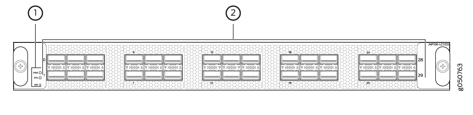
1 — Power LED (PWR), status LED (STS), and offline/online (OFF) button | 2 — Network ports |
Network Ports
Each of the 30 QSFP28 ports can operate as:
-
100GbE ports when you use QSFP28 optical transceivers.
-
40GbE ports when you use QSFP+ optical transceivers.
On the PTX10K-LC1105, the ports are enabled by default.
To change the mode, use the Junos OS operational command set chassis fpc slot-number pic 0 port port number channelization-speed speed.
Channelizing 40-Gigabit Ethernet Ports
Each of the 40-Gigabit Ethernet ports on the PTX10K-LC1105 line card can be channelized into four 10-Gigabit Ethernet, or channels. When ports are in channelization mode, the fourth port on each Packet Forwarding Engine is disabled, and the remaining four ports that are mapped to the same Packet Forwarding Engine can be used as either 4x10-Gigabit Ethernet, 40-Gigabit Ethernet, or 100-Gigabit Ethernet ports. The channelization mode works independently for each of the Packet Forwarding Engines on the PTX10K-LC1105 line card. See Table 19 for the maximum port configurations.
|
Port Speed |
Nonchannelized Mode (Mode D) |
Channelized Mode (Mode A) |
|---|---|---|
|
100 Gbps |
30 or |
24 or |
|
40 Gbps |
30 |
24 or |
|
10 Gbps |
0 |
96 |
The port behavior in the PTX10K-LC1105 line card is tied to the ASIC associated with the port. You must configure each port individually, in order to channelize a 40-Gigabit Ethernet port to four independent 10-Gigabit Ethernet ports. For example, ASIC PE0 maps to ports 0, 2, 4, 6, and 8. The fourth port, port 6, is disabled. See Table 20 for the list of available ports and the associated ASIC mapping in Figure 12 to locate the available and disabled ports.
If you change the channelization mode (mode D to mode A or mode A to mode D), the
new port speed configuration does not cause an FPC to reboot automatically, but
it triggers an FPC need bounce alarm. To ensure that the new
port speed configuration takes effect, you must manually reboot the FPC. The
alarm is cleared when you manually reboot the FPC or delete the new port speed
configuration.
When port speeds are changed manually from one setting to another, or when the
interface is deactivated, the show interface
interface-name command shows the error
Device interface-name not found for a
brief interval. Ensure that the transceiver is in a working condition. The
interface comes up subsequently.
|
ASIC |
Available Ports |
Disabled Port |
|---|---|---|
|
PE0 |
0, 2, 4, 8 |
6 |
|
PE1 |
1, 3, 5, 9 |
7 |
|
PE2 |
10, 12, 14, 18 |
16 |
|
PE3 |
11, 13, 15, 19 |
17 |
|
PE4 |
20, 22, 24, 28 |
26 |
|
PE5 |
21, 23, 25, 29 |
27 |
Power and Status LEDs
The two LEDs to the left of the network ports indicate the power (PWR) and status (STS) for the line card. See Table 21 and Table 22.
|
Color |
State |
Description |
|---|---|---|
|
Unlit |
Off |
There is no power to the line card. |
|
Green |
On steadily |
The line card has power. |
|
Yellow or amber |
Blinking |
The line card has a power fault. |
|
Color |
State |
Description |
|---|---|---|
|
Unlit |
Off |
The line card is offline or disabled. |
|
Green |
On steadily |
The line card is online. |
|
Yellow or amber |
On steadily |
The line card is booting. |
|
Blinking |
The line card has a fault condition or alarm. |
|
|
Slow blink or blip |
The beacon function is enabled. |
Port Status and Activity LEDs
Each QSFP28 port has a bicolored up or down LED indicator that shows port status and link activity. See Figure 13 and Table 23.
|
Color |
State |
Description |
|---|---|---|
|
Unlit |
Off |
The port is administratively disabled, there is no power, the link is down, or a transceiver is not present. |
|
Green |
On steadily |
A link is established but there is no activity. |
|
Blinking |
A link is up and there is activity. |
|
|
Yellow or amber |
Slow blink or blip |
The beacon function is enabled on the port. |
|
Blinking |
A single LED blinking indicates an interface fault. |
PTX10K-LC1201-36CD Line Card
The PTX10K-LC1201-36CD (model number: JNP10K-LC1201) is a 36-port line card that provides a line rate throughput of 14.4 Tbps. The 36 QSFP56-DD ports support a speed of up to 400 Gbps (see Figure 14). You can channelize the ports to operate at 200-Gbps, 100-Gbps, 50-Gbps, 25-Gbps, or 10-Gbps speed by using breakout cables.
Overview
The line card houses five Juniper Networks' custom ASICs, and each ASIC houses two Packet Forwarding Engines. One packet forwarding engine in the fifth ASIC is not used.
You can install the PTX10K-LC1201-36CD line card in the PTX10004, PTX10008, and PTX10016 chassis horizontally at the front of the chassis.

1 — Handles | 3 — Power LED (PWR), status LED (STS), and offline button (OFF) |
2 — Network ports and LEDs |
PTX10004 routers running Junos OS Evolved Release 20.3R1 with Junos Continuity and later support the PTX10K-LC1201-36CD line card. PTX10008 routers running Junos OS Evolved Release 19.4R1-S1 and later support the PTX10K-LC1201-36CD line card. PTX10016 routers running Junos OS Evolved Release 21.2R2 and later support the PTX10K-LC1201-36CD line card. The PTX10K-LC1201-36CD line card interoperates with the PTX10K-LC1202-36MR line card on a PTX10004, PTX10008, or PTX10016 router. The PTX10K-LC1201-36CD line card interoperates with the PTX10K-LC1301-36DD line card in PTX10004 and PTX10008 routers.
|
Component (Field Replaceable Unit) |
Part Number for the PTX10004 |
Part Number for the PTX10008 |
Part Number for the PTX10016 |
|---|---|---|---|
|
Switch fabric: Switch Interface Board (SIB) |
JNP10004-SF3 |
JNP10008-SF3 or JNP10008-SF5 The support for JNP10008-SF5 is available from Junos OS Evolved Release 24.4R2. |
JNP10016-SF3 |
|
Routing and Control Board (RCB) |
JNP10K-RE3-E, JNP10K-RE3-E-LT, JNP10K-RE2-E128, JNP10K-RE1-E128, JNP10K-RE1-ELT, or JNP10K-RE1-E |
JNP10K-RE3-E, JNP10K-RE3-E-LT, JNP10K-RE2-E128, JNP10K-RE1-E128, JNP10K-RE1-ELT, or JNP10K-RE1-E |
JNP10K-RE3-E, JNP10K-RE3-E-LT, JNP10K-RE2-E128, JNP10K-RE1-E128, JNP10K-RE1-ELT, or JNP10K-RE1-E |
|
Fan tray |
JNP10004-FAN2, JNP10004-FAN3 |
JNP10008-FAN2, JNP10008-FAN3 |
JNP10016-FAN2 |
|
Fan tray controller |
JNP10004-FTC2, JNP10004-FTC3 |
JNP10008-FTC2, JNP10004-FTC3 |
JNP10016-FTC2 |
|
Power supply |
JNP10K-PWR-AC2, JNP10K-PWR-AC3, JNP10K-PWR-DC2, JNP10K-PWR-DC3, JNP10K-PWR-AC3H |
JNP10K-PWR-AC2, JNP10K-PWR-AC3, JNP10K-PWR-DC2, JNP10K-PWR-DC3, JNP10K-PWR-AC3H |
JNP10K-PWR-AC2 JNP10K-PWR-AC3, JNP10K-PWR-DC2, JNP10K-PWR-DC3, JNP10K-PWR-AC3H |
Network Ports
The QSFP56-DD ports support:
-
400GbE transceivers (QSFP56-DD)
-
400GbE active optic cables (QSFP56-DD AOCs)
-
4 x 100GbE transceivers (QSFP56-DD)
-
2 x 100GbE transceivers (QSFP28-DD)
-
100GbE transceivers (QSFP28)
-
100GbE AOCs (QSFP28)
-
40GbE transceivers (QSFP+)
-
40GbE to 10GbE QSA (Junos OS Release 20.2R1 and later)
Channelization
All 36 ports of the PTX10K-LC1201-36CD line card default to 400GbE. You can either set all the ports to a specific speed and channelization or channelize each port individually. The CLI syntax to channelize a port on the PTX10K-LC1201-36CD is release dependent.
For software releases from Junos OS Evolved Release 19.4R1-S1 to Junos OS Evolved Release 20.1R2:
Use the pic-mode and speed options in the Junos OS Evolved
operational mode set chassis command:
user@host> set chassis fpc slot slot-number pic 0 pic-mode speed 400g|200g|100g|50g|40g|25g|10g
In this example, fpc slot represents the line card slots. There is a single
PIC in the PTX10K-LC1201-36CD; it is always numbered zero. The pic-mode option
indicates that you are configuring all of ports on the PIC and not an individual port. With the
speed options, you can configure 100-Gbps or 40-Gbps speed on all 36 ports, or
you can configure four 10-Gbps channels on each of the 36 ports.
For example, to set 100-Gbps speed on all ports in slot 2:
user@host> set chassis fpc 2 pic 0 pic-mode speed 100g
To individually configure a port, you need to specify both the speed and number of subports (channels).
user@host> set chassis fpc fpc-number pic 0 port port-number speed 400g|200g|100g|50g|40g|25g|10g number-of-subports subport-number
For example, to channelize port 15 in slot 0 to 4 downstream 100GbE interfaces:
user@host> set chassis fpc 0 pic 0 port 15 speed 100g number-of-subports 4
The resulting interfaces would be:
et-0/0/15:0
et-0/0/15:1
et-0/0/15:2
et-0/0/15:3
If you do not specify the number-of-subports value when configuring an
individual port, the system defaults to a value of 1. The same example, without the
number-of-subports option, would then result in one downstream 100GbE
interface.
For software releases Junos OS Evolved Release 20.1R2 and later, the speed
and number-of-subports options are in the interfaces
hierarchy. For example, to channelize port 15 in slot 0 to four downstream 100GbE
interfaces:
[edit-interfaces]
user@host> et-0/0/15
 {speed 100g;
number-of-subports 4;
}
et-0/0/15:0 {unit 0}
et-0/0/15:1 {unit 0}
et-0/0/15:2 {unit 0}
et-0/0/15:3 {unit 0}
After you save and commit the changes, each of the following resulting interfaces would be:
et-0/0/15:0
et-0/0/15:1
et-0/0/15:2
et-0/0/15:3
Bandwidth Support
Table 25 lists the bandwidth supported by each PTX10K-LC1201-36CD line card.
|
Number of SIBs Used |
Bandwidth per Slot Without Fabric Redundancy |
|---|---|
|
6 |
14.4 Tbps |
|
5 |
12 Tbps |
|
4 |
9.6 Tbps |
|
3 |
7.2 Tbps |
Network LEDs
Each network port has a single tricolored LED that indicates link activity and status. The red, amber, and green colors on the LED have different interpretations depending on whether the port is channelized or not channelized, and whether the beacon is activated. If the beacon feature is activated on the port, the port blinks.
|
Port Status |
Normal State |
Description |
|---|---|---|
|
Nonchannelized |
Unlit, off |
A transceiver is not installed or the link is down because of a loss of signal. |
|
Green, on steadily |
A link is established. |
|
|
Amber, on steadily |
The link is down because of a remote error or because the port was disabled through the CLI. |
|
|
Red, on steadily |
The link is down because of a hardware failure or a local error. |
|
|
Channelized |
Unlit, off |
All channels are down because of loss of signal. |
|
Green, on steadily |
A link is established and all channels are up. |
|
|
Amber, on steadily |
Applies to all other cases. |
|
|
Red, on steadily |
The port has a hardware failure. |
Line Card Status LEDs
The line card has a power LED (PWR) and a status LED (STS).
|
LED |
State |
LED Indication |
Beacon/Port Location On |
|---|---|---|---|
|
Power (PWR) |
The line card has no power. |
Off |
Off |
|
The line card has power and is operating correctly. |
Green, on steadily |
Green, on steadily |
|
|
The line card has a fault condition. |
Red, on steadily |
Red, on steadily |
|
|
Status (STS) |
The line card is disabled or offline. |
Off |
Off |
|
The line card is online and operating correctly. |
Green, on steadily |
Green, blinking |
|
|
The line card is booting. |
Green, blinking |
Green, blinking |
|
|
The line card has a fault condition. |
Red, on steadily |
Red, blinking |
PTX10K-LC1202-36MR Line Card
- Overview
- Components Required for PTX10K-LC1202-36MR
- Network Ports and Channelization
- Bandwidth Support
- Network LEDs
- Line Card Status LEDs
Overview
The PTX10K-LC1202-36MR (model number: JNP10K-LC1202) is a 36-port line card that provides a line rate throughput of 4.8 Tbps. The line card has 32 QSFP28 ports, each capable of supporting a maximum speed of 100 Gbps, and four QSFP56-DD ports, each capable of supporting a maximum speed of 400 Gbps (see Figure 15).
In a pure 100-Gbps port speed configuration, the line card supports a throughput of 3.6 Tbps (each of the 36 ports runs at 100-Gbps speed).
In a mixed-speed configuration of 100 Gbps and 400 Gbps, the line card supports a line rate throughput of 4.8 Tbps (thirty-two 100-Gbps ports and four 400-Gbps ports).
The line card houses two Juniper Networks' custom ASICs, and each ASIC houses two Packet Forwarding Engines. The line card supports a maximum throughput of 1.2 Tbps per Packet Forwarding Engine.
You can install the PTX10K-LC1202-36MR line card in the PTX10004, PTX10008, and PTX10016 chassis horizontally at the front of the chassis.
The acoustics noise for the line card is 85 dBA.
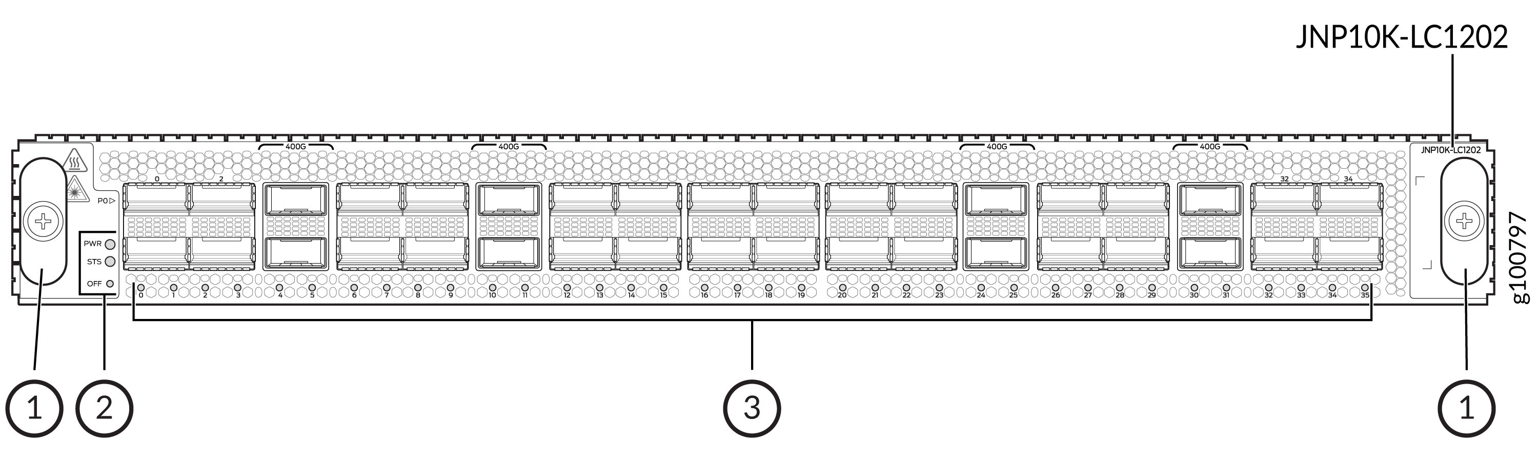
1 — Handles | 3 — Network ports and LEDs |
2 — Power LED (PWR), status LED (STS), and offline button (OFF) |
Components Required for PTX10K-LC1202-36MR
PTX10004 routers running Junos OS Evolved Release 20.3R1 with Junos Continuity and later support the PTX10K-LC1202-36MR line card. PTX10008 routers running Junos OS Evolved Release 20.3R1 and later (with Junos Continuity) support the PTX10K-LC1202-36MR line card. PTX10016 routers running Junos OS Evolved Release 21.2R2 and later support the PTX10K-LC1202-36MR line card. The PTX10K-LC1202-36MR line card interoperates with the PTX10K-LC1201-36CD line card on a PTX10004, PTX10008, or PTX10016 router. The PTX10K-LC1202-36MR line card interoperates with the PTX10K-LC1301-36DD line card in PTX10004 and PTX10008 routers.
|
Component (FRU) |
Part Number for the PTX10004 |
Part Number for the PTX10008 |
Part Number for the PTX10016 |
|---|---|---|---|
|
Switch fabric: Switch Interface Board (SIB) |
JNP10004-SF3 |
JNP10008-SF3 or JNP10008-SF5 The support for JNP10008-SF5 is available from Junos OS Evolved Release 24.4R2. |
JNP10016-SF3 |
|
Routing and Control Board (RCB) |
JNP10K-RE3-E, JNP10K-RE3-E-LT, JNP10K-RE2-E128, JNP10K-RE1-E128, JNP10K-RE1-ELT, or JNP10K-RE1-E |
JNP10K-RE3-E, JNP10K-RE3-E-LT, JNP10K-RE2-E128, JNP10K-RE1-E128, JNP10K-RE1-ELT, or JNP10K-RE1-E |
JNP10K-RE3-E, JNP10K-RE3-E-LT, JNP10K-RE2-E128, JNP10K-RE1-E128, JNP10K-RE1-ELT, or JNP10K-RE1-E |
|
Fan tray |
JNP10004-FAN2, JNP10004-FAN3 |
JNP10008-FAN2, JNP10008-FAN3 |
JNP10016-FAN2 |
|
Fan tray controller |
JNP10004-FTC2, JNP10004-FTC3 |
JNP10008-FTC2, JNP10008-FTC3 |
JNP10016-FTC2 |
|
Power supply |
JNP10K-PWR-AC2, JNP10K-PWR-AC3, JNP10K-PWR-DC2, JNP10K-PWR-DC3, or JNP10K-PWR-AC3H |
JNP10K-PWR-AC2, JNP10K-PWR-AC3, JNP10K-PWR-DC2, JNP10K-PWR-DC3, or JNP10K-PWR-AC3H |
JNP10K-PWR-AC2 or JNP10K-PWR-DC2, JNP10K-PWR-DC3, or JNP10K-PWR-AC3H |
Network Ports and Channelization
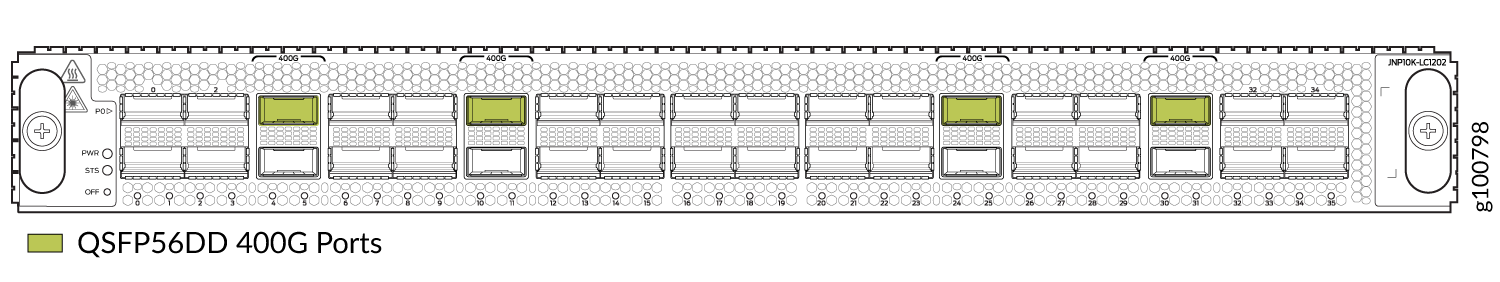
On the PTX10K-LC1202-36MR line card, the ports 4, 10, 24, and 30 are 400GbE (QSFP56-DD) ports, whereas the rest are 100GbE (QSFP28) ports.
Figure 16 shows the 400GbE ports highlighted.
By using breakout cables, you can channelize the PTX10K-LC1202-36MR ports.
The QSFP56-DD ports (ports 4, 10, 24, and 30) on the line card support the following transceivers:
-
1x400GbE transceivers (QSFP56-DD)
-
4x100GbE transceivers (QSFP56-DD)
-
2x100GbE transceivers (QSFP28-DD)
-
1x100GbE transceivers (QSFP28)
-
2x50GbE transceivers (QSFP28)
-
1x40GbE transceivers (QSFP+)
-
8x25GbE transceivers (QSFP28-DD)
-
4x25GbE transceivers (QSFP28)
-
4x10GbE transceivers (QSFP+)
-
1x10GbE transceivers (SFP+)
-
40GbE to 10GbE QSA, starting in Junos OS Evolved Release 20.4R1 and later.
The QSFP28 ports 0, 2, 5 through 9, 11 through 18, 20, 22, 23, 25 through 29, and 31 through 35 on the line card support the following transceivers:
-
1x100GbE transceivers (QSFP28)
-
2x50GbE transceivers (QSFP+)
-
1x40GbE transceivers (QSFP+)
-
4x25GbE transceivers (QSFP28)
-
4x10GbE transceivers (QSFP+)
-
1x10GbE transceivers (QSFP+)
The QSFP28 ports 1, 3, 19, and 21 on the line card support the the 1x100GbE QSFP28 transceivers.
The ports 1, 3, 19, and 21 must be configured as unused if the preceding ports (0, 2, 18, and 20) are not in 100-Gbps mode. This means, of the 36 ports on the PTX10K-LC1202-36MR line card, only 32 ports are available to be configured as 4x25GbE and 4x10GbE ports.
See the Port Checker tool to see the supported port speeds.
You can configure port speeds at the interface level using the set interfaces <interface-name> speed <speed> command.
Bandwidth Support
Table 29 explains the bandwidth supported by each PTX10K-LC1202-36MR line card.
|
Number of SIBs Used |
Bandwidth per Slot Without Fabric Redundancy |
|---|---|
|
6 |
4.8 Tbps |
|
5 |
4 Tbps |
|
4 |
3.2 Tbps |
|
3 |
2.4 Tbps |
Network LEDs
Each network port has a single tricolored LED that indicates link activity and status. The red, amber, and green colors on the LED have different interpretations depending on whether the port is channelized or not channelized, and whether the beacon is activated. If the beacon feature is activated on the port, the port blinks.
|
Port Status |
State |
Description |
|---|---|---|
|
Nonchannelized |
Unlit, off |
A transceiver is not present in the port, or the link is down because of a loss of signal. |
|
Green, on steadily |
A link is established. |
|
|
Amber, on steadily |
The link is down because of a remote error or because the port was disabled through the CLI. |
|
|
Red, on steadily |
The link is down because of a hardware failure or a local error. |
|
|
Channelized |
Unlit, off |
All channels are down because of loss of signal. |
|
Green, on steadily |
A link is established and all channels are up. |
|
|
Amber, on steadily |
Applies to all other cases. |
|
|
Red, on steadily |
The port has a hardware failure. |
Line Card Status LEDs
The line card has a power LED (PWR) and a status LED (STS).
|
LED |
State |
LED Indication |
Beacon/Port Location On |
|---|---|---|---|
|
Power (PWR) |
The line card has no power. |
Off |
Off |
|
The line card has power and is operating correctly. |
Green, on steadily |
Green, on steadily |
|
|
The line card has a fault condition. |
Red, on steadily |
Red, on steadily |
|
|
Status (STS) |
The line card is disabled or offline. |
Off |
Off |
|
The line card is online and operating correctly. |
Green, on steadily |
Green, blinking |
|
|
The line card is booting. |
Green, blinking |
Green, blinking |
|
|
The line card has a fault condition. |
Red, on steadily |
Red, blinking |
PTX10K-LC1301-36DD Line Card
- Overview
- Boot Time
- Components Required
- Bandwidth Support
- Network Port Status LEDs
- Line Card Status LEDs
Overview
The PTX10K-LC1301-36DD line card (model number: JNP10K-LC1301) is a 36-port line card that offers a line rate throughput of 28.8 Tbps. The 36 high-density 800-Gigabit Ethernet (800GbE) QSFP-DD ports support speeds of up to 800 Gbps. The line card houses two Juniper Networks' custom Express 5 ASICs, and each ASIC comprises of two Packet Forwarding Engines.
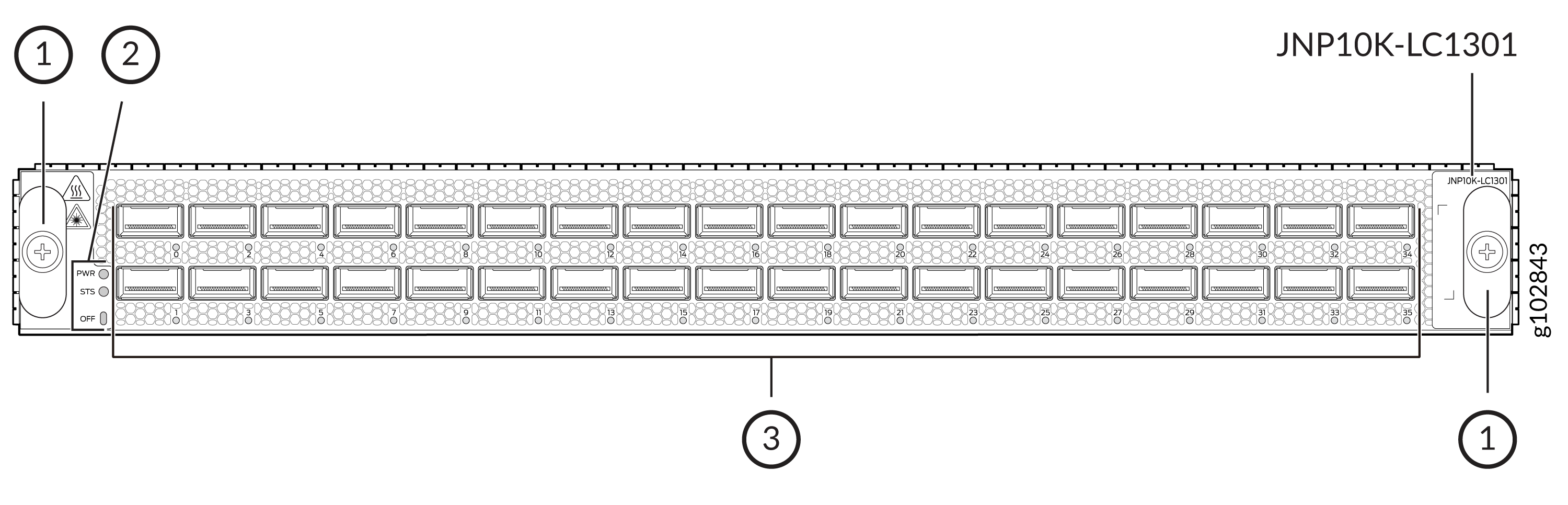
1 — Handles | 3 — Network ports and LEDs |
2 — Power LED (PWR), status LED (STS), and offline button (OFF) |
The ports support QSFP+, QSFP28, QSFP56-DD, and 400G-ZR transceivers. When the line card is operating in the normal power mode, you can install up to 36 800-Gbps or 2x400 Gbps transceivers.
You can also use breakout cables, active optical cables (AOCs), and the number-of-sub-ports (interface) configuration to channelize the ports to operate at the following speeds:
-
1x800 Gbps
-
2x400 Gbps
-
1x400 Gbps
-
8x100 Gbps
-
7x100 Gbps
-
6x100 Gbps
-
5x100 Gbps
-
4x100 Gbps
-
3x100 Gbps
-
2x100 Gbps
-
1x100 Gbps
-
8x50 Gbps
-
4x50 Gbps
-
2x50 Gbps
-
1x40 Gbps
-
8x25 Gbps
-
4x25 Gbps
-
4x10 Gbps
-
1x10 Gbps
The line card supports fabric link evaluation.
The links on the ports come up at 800-Gbps speed by default. You can change the port speed by using the set interfaces <interface-name> speed <speed> command.
Juniper Networks Port Checker (https://apps.juniper.net/port-checker/) provides a visual representation of various Juniper network devices, and assists to configure and validate different port combinations.
The software features for the line card are documented in Release Notes: Junos OS Evolved Release 24.4R1.
Boot Time
The boot time for the line card is approximately 566 seconds.
Components Required
|
Component |
Part Number for the PTX10008 |
Part Number for the PTX10004 |
|---|---|---|
|
Switch Interface Board (SIB) |
JNP10008-SF5 or JNP10008-SF3 Support for JNP10008-SF3 is available from Junos OS Evolved Release 25.4R1-S1. |
JNP10004-SF3 Support for JNP10004-SF3 is available from Junos OS Evolved Release 25.4R1-S1. |
|
Routing and Control Board (RCB) |
JNP10K-RE2-E128, JNP10K-RE1-E128, JNP10K-RE1-ELT, JNP10K-RE1-E, JNP10K-RE3-E, or JNP10K-RE3-E-LT |
JNP10K-RE2-E128, JNP10K-RE1-E128, JNP10K-RE1-ELT, JNP10K-RE1-E, JNP10K-RE3-E, or JNP10K-RE3-E-LT |
|
Fan tray |
JNP10008-FAN3 |
JNP10004-FAN3 |
|
Fan tray controller |
JNP10008-FTC3 |
JNP10004-FTC3 |
|
Power supply |
JNP10K-PWR-AC3, JNP10K-PWR-DC3, or JNP10K-PWR-AC3H |
JNP10K-PWR-AC3, JNP10K-PWR-DC3, or JNP10K-PWR-AC3H |
Bandwidth Support
|
Number of JNP10008-SF5 SIBs Used |
Bandwidth per Slot |
|---|---|
|
6 |
28.8 Tbps |
|
5 |
24 Tbps |
|
4 |
19.2 Tbps |
|
3 |
14.4 Tbps |
|
Number of JNP10004-SF3 or JNP10008-SF3 SIBs Used |
Bandwidth per Slot |
|---|---|
|
6 |
12.8 Tbps |
|
5 |
10.7 Tbps |
|
4 |
8.6 Tbps |
|
3 |
6.4 Tbps |
The maximum throughput that the line card offers in PTX10004 routers with JNP10004-SF3 installed and in PTX10008 routers with JNP10008-SF3 installed is 12.8 Tbps. The total throughput that a port group of nine ports (0 through 8, 9 through 17, 18 through 26, and 27 through 35) can offer is 3.2 Tbps. If a port group is oversubscribed, traffic is dropped at ingress, overriding the Class of Service (CoS) profiles.
Network Port Status LEDs
Each network port has a single tricolored LED that indicates link activity and status. The red, amber, and green colors on the LED have different interpretations depending on whether the port is channelized or not channelized, and whether the beacon is activated. If the beacon feature is activated on the port, the port blinks.
|
Port Status |
Description |
Color and State |
Beacon/Port Location On |
|---|---|---|---|
|
Not channelized |
A link is established. |
Green, on steadily |
Green, blinking |
|
The link is down because of a remote error or because the port was disabled through the CLI. |
Amber, on steadily |
Amber, blinking |
|
|
The link is down because of a hardware failure or a local error. |
Red, on steadily |
Red, blinking |
|
|
The port doesn't have a transceiver installed or the link is down because of a loss of signal. |
Unlit, off |
Green, blinking |
|
|
Channelized |
A link is established and all the channels are up. |
Green, on steadily |
Green, blinking |
|
All the other scenarios. |
Amber, on steadily |
Amber, blinking |
|
|
The port has a hardware failure or a fault. |
Red, on steadily |
Red, blinking |
|
|
All channels are down because of loss of signal. |
Unlit, off |
Green, blinking |
Line Card Status LEDs
The line card has a power LED (PWR) and a status LED (STS).
|
LED |
Description |
LED Color and State |
Beacon/Port Location On |
|---|---|---|---|
|
Power (PWR) |
The line card has power and is operating correctly. |
Green, on steadily |
Green, on steadily |
|
The line card has a fault condition. |
Red, on steadily |
Red, on steadily |
|
|
The line card has no power. |
Off |
Off |
|
|
Status (STS) |
The line card is online and operating correctly. |
Green, on steadily |
Green, blinking |
|
The line card is booting. |
Green, blinking |
Green, blinking |
|
|
Line card fabric link evaluation is in progress. |
Green, blipping |
Green, blinking |
|
|
The line card has improper fabric connectivity. |
Amber, on steadily |
Amber, blinking |
|
|
The line card has a fault condition. |
Red, on steadily |
Red, blinking |
|
|
The line card is disabled or offline. |
Off |
Off |
QFX10000-60S-6Q Line Card
- Hardware Features
- Port Groups
- Channelization of 40GbE Ports
- Using Copper and Fiber SFP Transceivers
- SFP+ Status and Activity LEDs
- QSFP+ and QSFP28 Status and Activity LEDs
Hardware Features
The QFX10000-60S-6Q line card consists of 60 small form-factor pluggable plus (SFP+) ports that support 10-Gbps or 1-Gbps port speed, 2 dual-speed QSFP28 ports that support either 40-Gbps or 100-Gbps port speed, and 4 QSFP+ ports that support 40-Gbps port speed. All of the QSFP and SFP+ ports are configured to 10 Gbps by default. The QSFP28 ports are configured as 40-Gbps speed ports by default, but port 60 and port 64 are dual-speed ports and can be configured to support either 10GbE or 40GbE optical transceivers. Ports 60 and 64 can also be configured to support 100GbE optical transceivers. See the Hardware Compatibility Tool for details of supported optical transceivers. See Figure 18.
The QFX10000-60S-6Q line card is supported on Junos OS Release 19.1R1 and later.
Junos OS Release 19.1R1 does not support 1GbE on the 10GbE SFP+ ports.
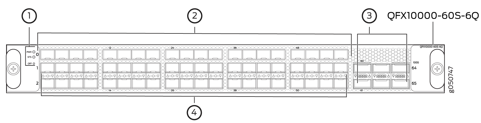
1 — Power LED (PWR), status LED (STS), and offline/online (OFF) button | 3 — QSFP28 ports, QSFP+ ports, and port groups |
2 — SFP+ ports |
Each QSFP28 port (60 and 64) controls a port group and can be configured as a:
100GbE port by using QSFP28 optical transceivers. The interface speeds are configured by port group. When a QSFP28 transceiver is inserted into one of the QSFP28 ports marked with a fine black line above the port (60 or 64) and the port is configured for 100GbE, the two adjacent ports are disabled and the QSFP28 port is enabled for 100GbE. When you configure port 60 for 100 Gbps, ports 61 and 62 are disabled; when you configure port 64 for 100 Gbps, ports 63 and 65 are disabled.
40GbE port by using QSFP+ optical transceivers. The default speed is 10 Gbps.
10GbE port by using breakout cables and attached optical transceivers. When configured for channelization, the system converts the 40GbE port into four independent 10GbE ports (or channels). Use the
set chassis fpc slot
                                slot-number pic slot
                                slot-number port port-number
                            speed speed
command to change the port speed.
Each QSFP+ port (61, 62, 63, and 65) is part of a port group and is controlled by one of the associated QSFP28 ports (60 or 64). If a QSFP28 port operates at 40-Gbps speed, then each of the QSFP+ ports can be configured as a:
40GbE port by using QSFP+ optical transceivers. The default speed is 10 Gbps.
10GbE port by using breakout cables with attached optical transceivers. When configured for channelization, the system converts the 40GbE port into four independent 10GbE ports (or channels). Use the
set chassis fpc slot
                                slot-number pic slot
                                slot-number port port-number speed
                                speed
command to change the port speed.
You can configure each SFP+ port (0 through 59) as a 10GbE port by using SFP+ optical transceivers. The default speed is 10 Gbps.
You can install copper SFP transceivers only on ports located in the lower two SFP+ port rows (at the bottom). Copper SFP transceivers are supported only on the bottom two SFP+ rows. The copper SFP transceivers (1000BASE-T) are limited to these rows because they are physically larger than optical SFP transceivers (1000BASE-X). Stacking copper SFP transceivers in all three rows causes internal damage to the line card. Optical SFP transceivers can be stacked and used in all SFP+ ports, 0 through 59.
You can configure any of the 66 ports 0 through 65 as either uplink or access ports. The ports are enabled by default, and the default configuration adds the ports to the default VLAN.
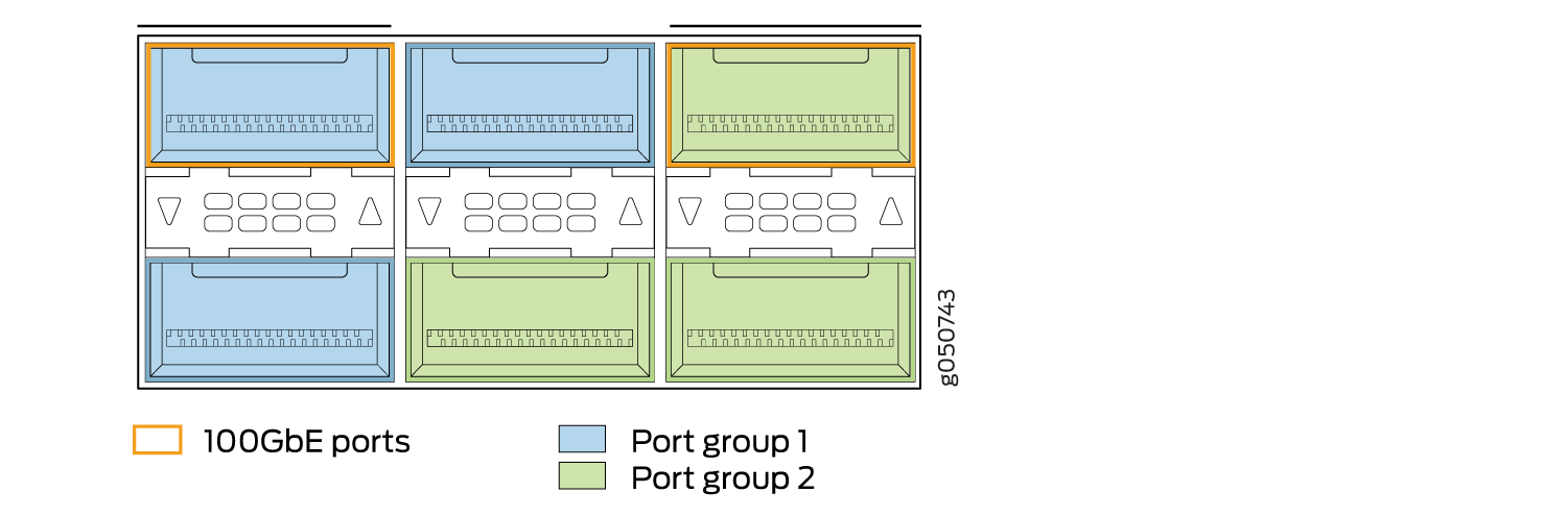
Port Groups
The six combination ports of QSFP28 and QSFP+ can operate either as six independent 40GbE ports or as two port groups. The first port group is controlled by QSFP28 port 60 and administratively bundled with QSFP+ ports 61 and 62. The second port group is controlled by QSFP28 port 64 and administratively bundled with QSFP+ ports 63 and 65. To enable the port group, insert a 100GbE transceiver into the QSFP28 port and configure the port as a 100-Gbps port. Junos OS enables the QSFP28 port at 100-Gbps speed and disables the two QSFP+ ports bundled in the port group. Figure 19 shows the location of QSFP28 ports and port groups for the QFX10000-60S-6Q. Table 37 shows the available combinations for the ports.
Port Number |
4X10GbE |
4X10GbE Channelized Port Group |
40GbE |
100GbE |
100GbE Disables |
|---|---|---|---|---|---|
60 |
✓ |
✓ |
✓ |
✓ |
61, 62 |
61 |
✓ |
✓ |
– |
– |
|
62 |
✓ |
✓ |
– |
– |
|
63 |
✓ |
✓ |
✓ |
– |
– |
64 |
✓ |
✓ |
✓ |
63, 65 |
|
65 |
✓ |
✓ |
– |
– |
Channelization of 40GbE Ports
Channelization from a 40GbE port into four independent 10GbE ports is supported on the QSFP28 and QSFP+ ports. Channelization to 50-Gbps or 25-Gbps speed is not supported on the 100GbE QSFP28 port. All ports in the port group are channelized when port 60 or port 64 is channelized. Ports cannot be channelized individually.
To channelize a 40-Gbps port to four independent 10-Gbps ports (or channels), use the set
chassis fpc slot slot-number pic slot
slot-number port port-number
channel-speed speed command. For example, to
channelize ports 60 through 62 for a
line card in slot 6:
[edit chassis fpc 6 pic 1]
user@router# set port 60 speed 10g
Review your configuration and issue the commit command.
If you want to return the port to the default, delete the speed statement from
the configuration at the [chassis fpc 6 pic 1 port
port-number] hierarchy level and commit the
configuration. The network port is reset to the default 40GbE interface.
[edit chassis fpc 6 pic 1]
user@router# delete port 60 speed 10g
Using Copper and Fiber SFP Transceivers
When you configure the 10GbE ports 0 to 59 as 1GbE ports, you can use optical fiber SFP transceivers in any of the ports. However, copper SFP transceivers are restricted to the lower two rows. See Figure 20.
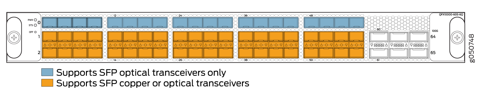
Stacking three copper SFP transceivers in a column can cause damage to the line card.
Because 1-Gbps copper SFP transceivers are physically larger than optical SFP transceivers, there is insufficient room for three copper SFP transceivers to be stacked. Use the top row only for optical SFP transceivers. You can stack copper transceivers in the bottom two rows. Ports are arranged belly-to-belly. Stacking three SFP transceivers in a column can damage the line card. For the recommended configuration, see Figure 21.
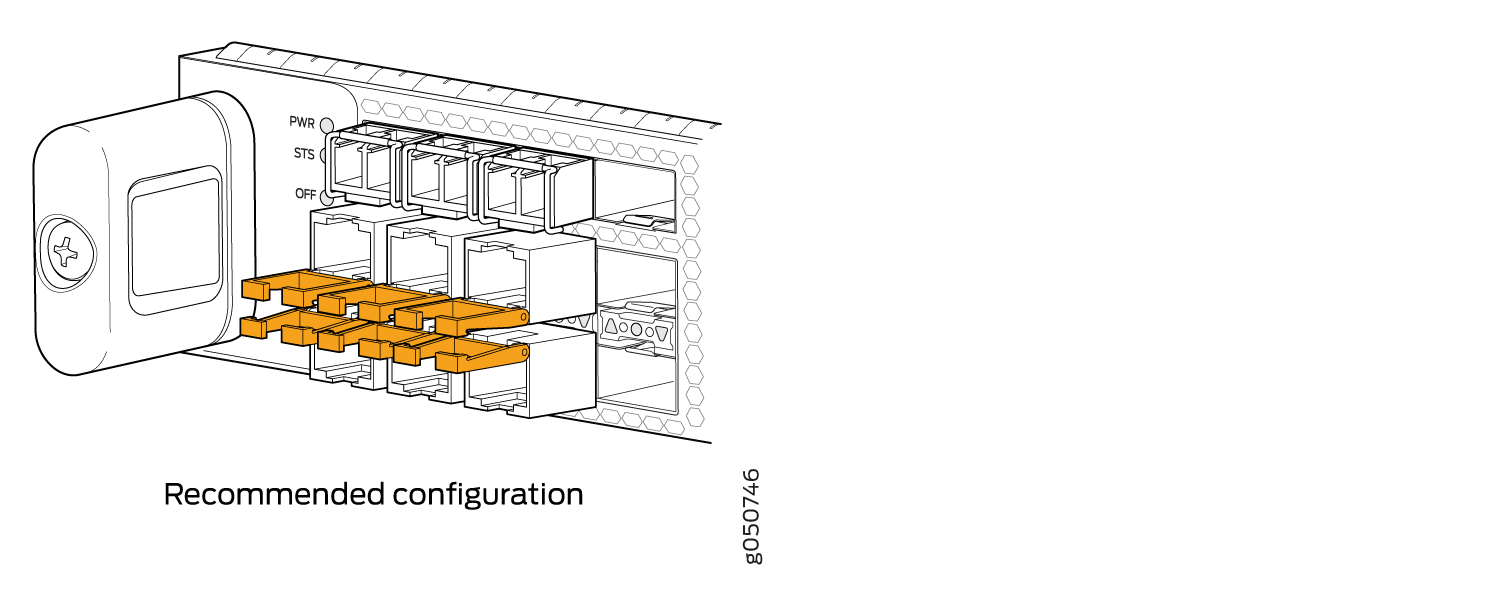
SFP+ Status and Activity LEDs
All status and activity LEDs for the SFP+ ports are located between the second and third rows of SFP+. The up arrow, circle, and down arrow indicate the row of the status. A bicolor LED indicates the status and activity. See Figure 22 and Table 38.
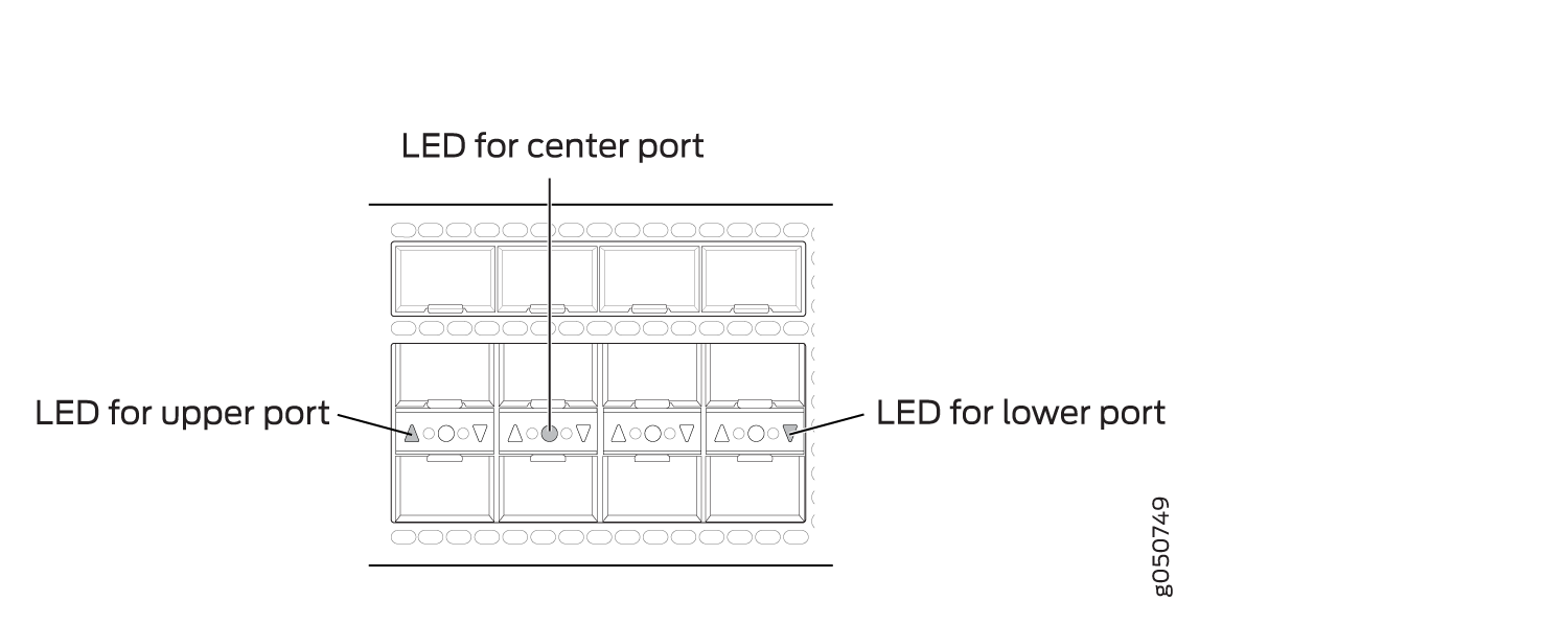
An up arrow indicates the first row.
A circle indicates the second row.
A down arrow indicates the third row.
Color |
State |
Description |
|---|---|---|
Unlit |
Off |
The port is administratively disabled, there is no power, the link is down, or a transceiver is not present. |
Green |
On steadily |
A link is established. |
Yellow or amber |
Slow blink, or blip |
The beacon function is enabled on one or more sub-channels. |
Blinking |
The interface has a fault condition. |
QSFP+ and QSFP28 Status and Activity LEDs
All QSFP+ and QSFP28 ports have an up or down indicator for each port and four bicolored LEDs that show port status and link activity based on whether or not the port is configured for channelization. See Table 39.
Color |
State |
Description |
|---|---|---|
Unlit |
Off |
The port is administratively disabled, there is no power, the link is down, or a transceiver is not present. All sub-channels are disabled. |
Green |
On steadily |
A link is established. When channelized, all sub-channels are up. When not channelized, it indicates no activity. |
Yellow or amber |
On steadily |
At least one channel link is up, but not all channels are up. |
Slow blink, or blip |
The beacon function is enabled on one or more sub-channels. |
|
Blinking |
One or more sub-channels has a fault condition. |
PTX10008 Line Card LEDs
All PTX10008 line cards have two bicolored LEDs. The PTX10K-LC1201-36CD LEDs are green and red, while the other line card LEDs are green and amber. See Figure 24.
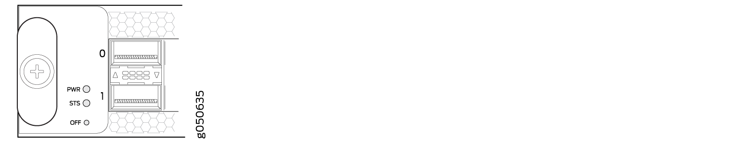
Table 40 describes the functions of the line card LEDs other than PTX10K-LC1201-36CD. See Table 41 for PTX10K-LC1201-36CD behavior.
Label |
Color |
State |
Description |
|---|---|---|---|
PWR |
Unlit |
Off |
The line card is not receiving power. |
Green |
On steadily |
The line card is receiving power. |
|
Yellow |
Blinking |
The line card has a power error, such as insufficient power. |
|
STS |
Unlit |
Off |
The line card is offline. |
Green |
On steadily |
The line card is online and functioning normally. |
|
Green |
Blinking |
The beacon feature is enabled on the line card. |
|
Yellow |
On steadily |
The line card is booting. |
|
Yellow |
Blinking |
The line card is detecting an error. |
Label |
Color |
Normal State |
Beacon Active State |
Description |
|---|---|---|---|---|
PWR |
Green |
On steadily |
On steadily |
The line card is receiving power. |
Red |
On steadily |
On steadily |
The line card is detecting an error. |
|
Unlit |
Off |
Off |
The line card is not receiving power. |
|
STS |
Green |
On steadily |
Blinking |
The line card is online. |
Green |
Blinking |
Blinking |
The line card is booting. |
|
Red |
On steadily |
Blinking |
The line card is detecting an error. |