Install and Remove PTX10008 Cooling System Components
The PTX10008 router has two independent, field-replaceable fan trays. To install or remove the fan trays and fan tray controller, see the following sections.
Install a PTX10008 Fan Tray
Before you begin to install a fan tray:
-
Ensure that you understand how to prevent ESD damage. See Prevention of Electrostatic Discharge Damage.
-
Ensure that you have the following parts and tools available to install a fan tray in a PTX10008 router:
-
Electrostatic discharge (ESD) grounding strap
-
A Phillips (+) screwdriver, number 1 or 2 (optional), for the captive screws
-
A replacement fan tray
-
Each fan tray is a hot-removable and hot-insertable field-replaceable unit (FRU); you can remove and replace the fan tray while the router is running without turning off power to the router or disrupting routing functions. There are three models of the fan tray, JNP10008-FAN, JNP10008-FAN2, and JNP10008-FAN3. You must not install different types of fan trays in the same chassis.
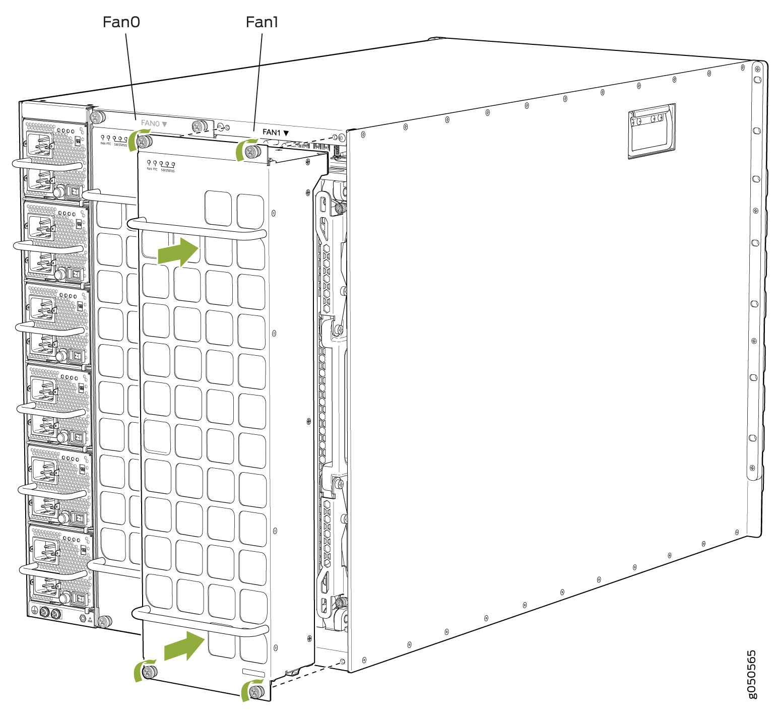
Each fan tray is installed vertically on the rear, or FRU side, of the chassis.
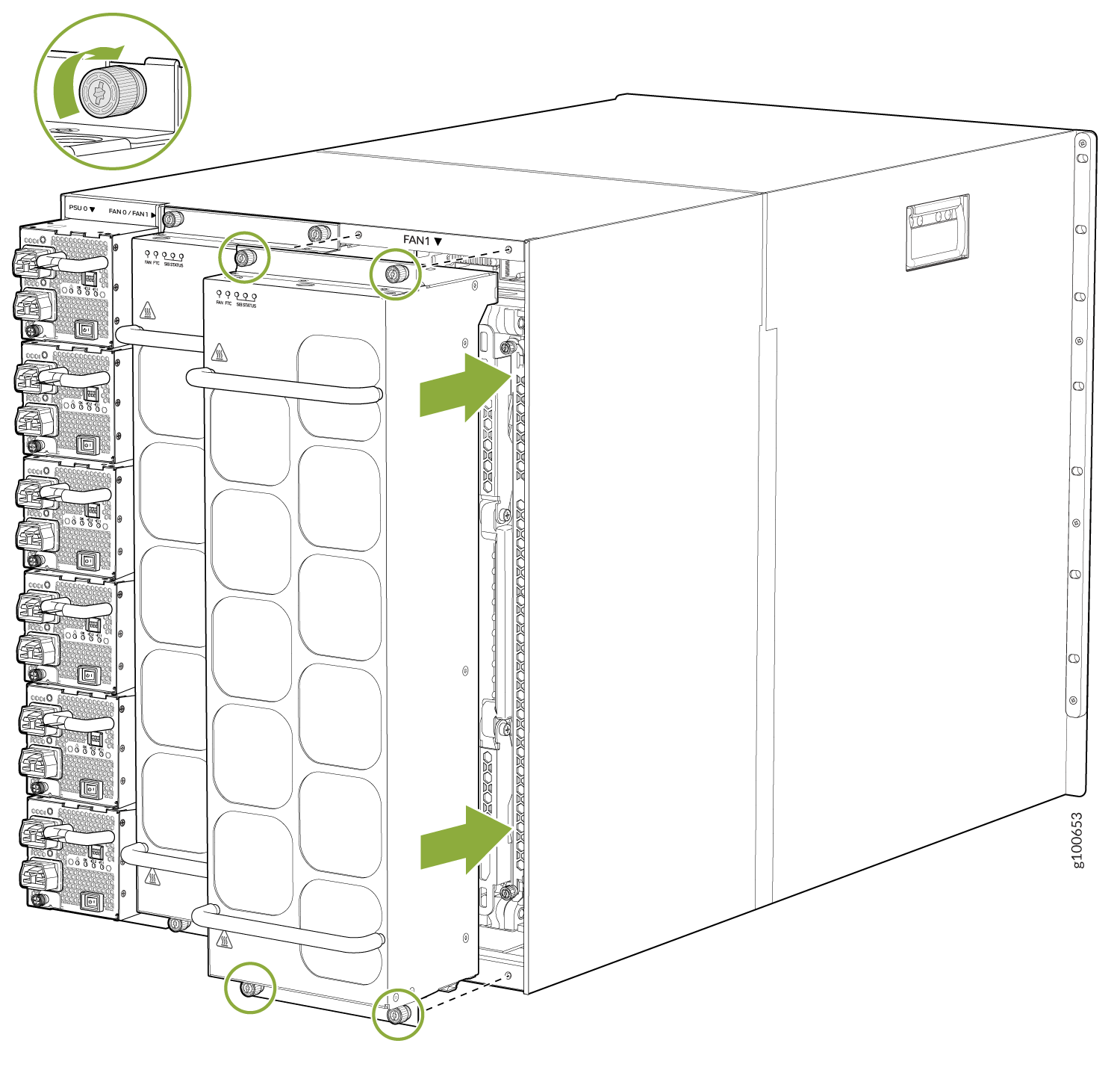
To install any PTX10008 fan tray:
- Wrap and fasten one end of the ESD grounding strap around
your bare wrist and connect the other end of the strap to one of the
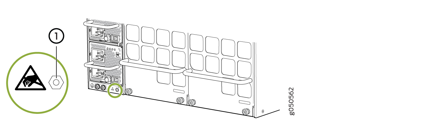
ESD points on the chassis (see Figure 1).Figure 1: ESD Point on the Rear of the PTX10008 Chassis
 1—
1—ESD point
Remove a PTX10008 Fan Tray
The PTX10008 chassis has two independent, field-replaceable fan trays. Each fan tray is a hot-removable and hot-insertable field-replaceable units (FRU); you can remove and replace the fan tray while the router is running without turning off power to the router or disrupting routing functions. There are three models of fan tray for the PTX10008 (JNP10008-FAN, JNP10008-FAN2, and JNP10008-FAN3).
Each fan tray is installed vertically on the rear, or FRU-side, of the chassis.
Before you remove a fan tray:
-
Ensure that you understand how to prevent ESD damage. See Prevention of Electrostatic Discharge Damage.
-
Ensure that you have the following parts and tools available:
-
Electrostatic discharge (ESD) grounding strap
-
A replacement fan tray
-
A Phillips (+) screwdriver, number 1 or 2 (optional), for the captive screws
-
If you are replacing the fan tray, run the fan tray at 100% speed for at least 10 minutes before you start the replacement procedure.
If Junos OS is installed in your router, use the test chassis fan tray 0
speed full-speed
and test chassis fan tray 1 speed full-speed
commands to configure the fans to operate at 100% speed.
If Junos OS Evolved is installed in your router, use the request chassis fan
tray 0 speed 100 and request chassis fan tray 1 speed
100 commands to configure the fans to operate at 100% speed.
After you replace the fan tray, you must configure the fan trays to operate at the
normal speed. If Junos OS is installed in your router, use the test chassis
fan tray 0 speed normal
and test chassis fan tray 1 speed normal
commands to configure the fan trays to operate at the normal speed. If
Junos OS Evolved is installed in your router, use the request chassis fan
tray 0 speed normal and request chassis fan tray 1 speed
normal commands to configure the fan trays to operate at the normal
speed.
You must replace only one fan tray at a time.
If you have JNP10008-SF or JNP10008-SF3 switch fabric installed in the router, you must replace the fan tray within the time mentioned in Table 1 of removing the fan tray to prevent overheating of the chassis. If you are removing a JNP10008-FAN2 or JNP10008-FAN3 fan tray to access a Switch Interface Board (SIB), we recommend that you either perform the necessary work during a maintenance window or reinstall the fan tray within time mentioned in Table 1. If you have JNP10008-SF5 switch fabric installed in the router, you must replace the fan tray within the time mentioned in Table 2 of removing the fan tray to prevent overheating of the chassis.
We recommend that you take offline the SIB behind the fan tray that you plan to
remove by using the request chassis sib slot slot number
offline command.
|
Chassis Ambient Temperature |
Duration |
|---|---|
|
20° C |
5 minutes |
|
30° C |
2.3 minutes |
|
40° C |
1.2 minutes |
|
Chassis Ambient Temperature |
Traffic (%) with 800-G ZR Transceivers Installed in 25% of the Ports |
Number of SIBs Offline |
Duration (mm:ss) |
|---|---|---|---|
|
25° C |
Up to 25% |
1 |
2:37 |
|
25° C |
Up to 25% |
2 |
3:27 |
|
25° C |
Up to 50% |
3 |
3:08 |
|
30° C |
Up to 25% |
3 |
3:35 |
|
30° C |
Up to 25% |
1 |
2:07 |
|
30° C |
Up to 25% |
2 |
2:39 |
|
30° C |
Up to 50% |
3 |
2:29 |
To remove a PTX10008 fan tray (JNP10008-FAN, JNP10008-FAN2, or JNP10008-FAN3):
-
Wrap and fasten one end of the ESD grounding strap around
your bare wrist and connect the other end of the strap to one of the
ESD points on the chassis (see Figure 5).
Figure 5: ESD Point on the Rear of the PTX10008
1—
ESD point
-
Grasp the top and bottom handles and pull the fan tray out about 3 in. (7.6 cm).
See Figure 6,
Figure 7, and
Figure 8.
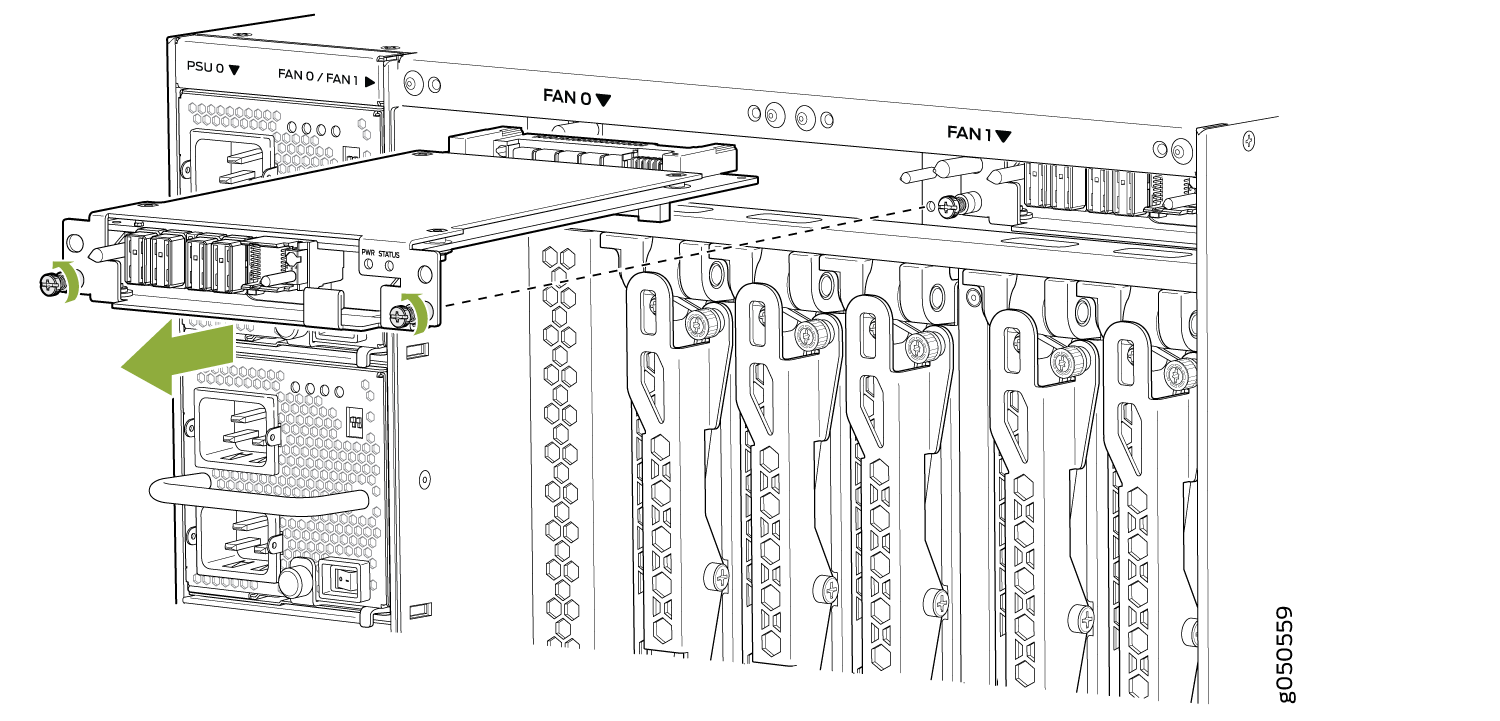
Figure 6: Remove a JNP10008-FAN Fan Tray
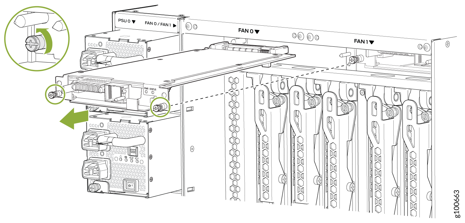
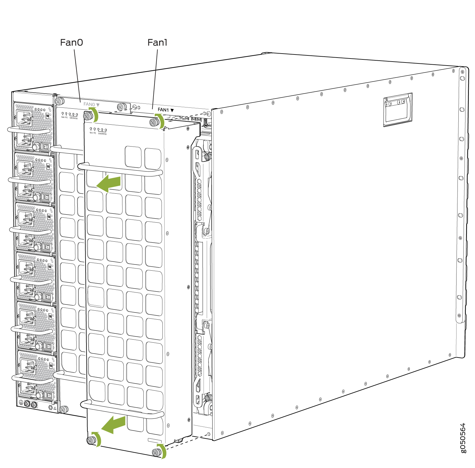 Figure 7: Remove a JNP10008-FAN2 Fan Tray
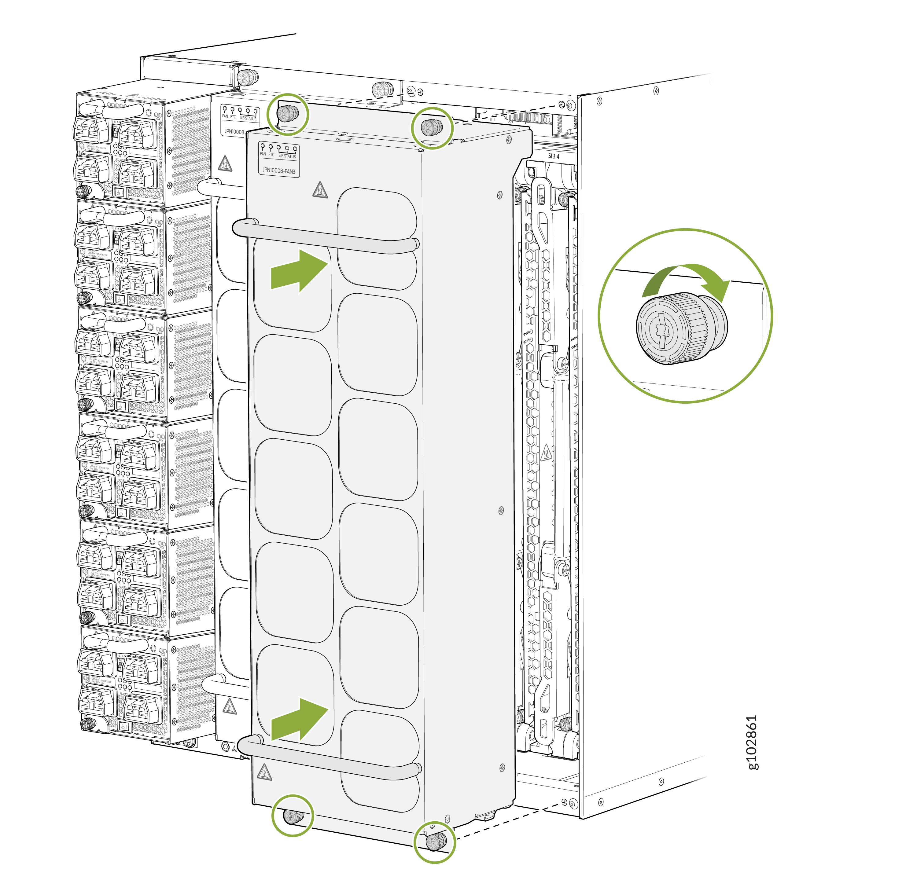
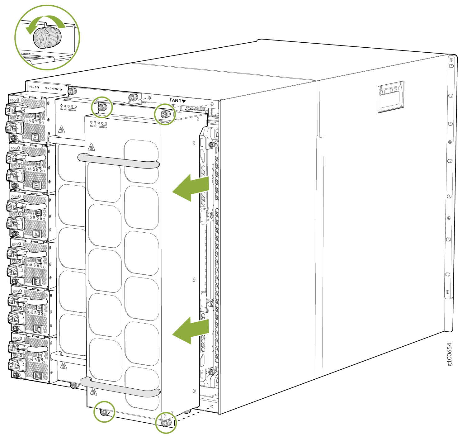 Figure 8: Remove a JNP10008-FAN3 Fan Tray
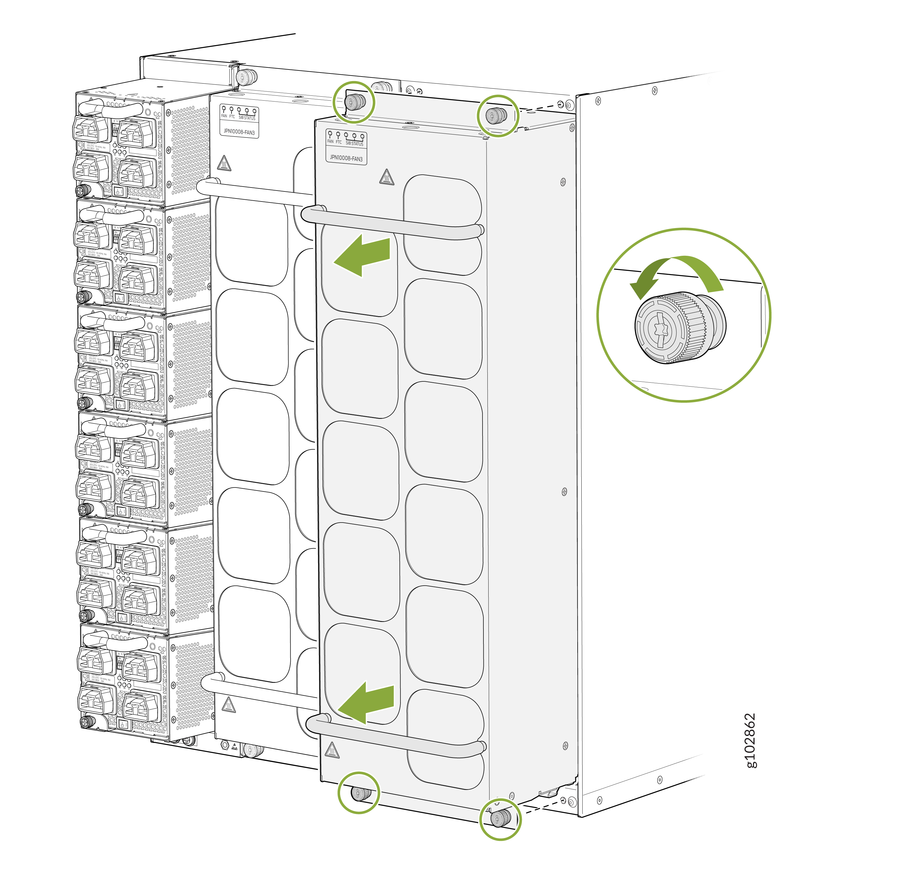
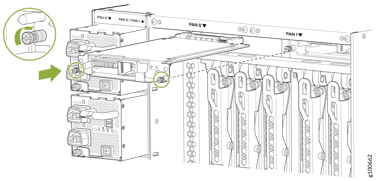
Install a PTX10008 Fan Tray Controller
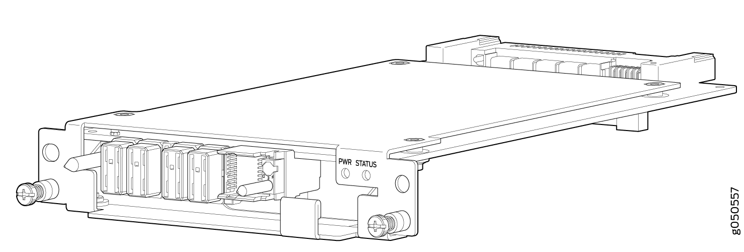
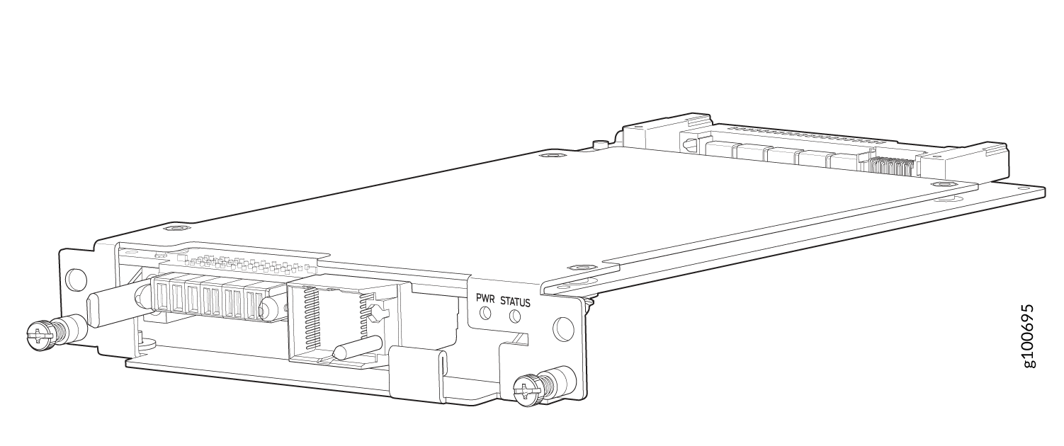
For each of the two fan trays, there is a fan tray controller. Each controller is a hot-removable and hot-insertable field-replaceable unit (FRU); you can remove and replace one fan tray controller while the router is running without turning off power to the router or disrupting routing functions. There are three models of fan tray controller for the PTX10008, JNP10008-FAN-CTRL, JNP10008-FTC2, and JNP10008-FTC3. See Figure 9 and Figure 10.
Do not remove the fan tray controller unless you have a replacement controller available.
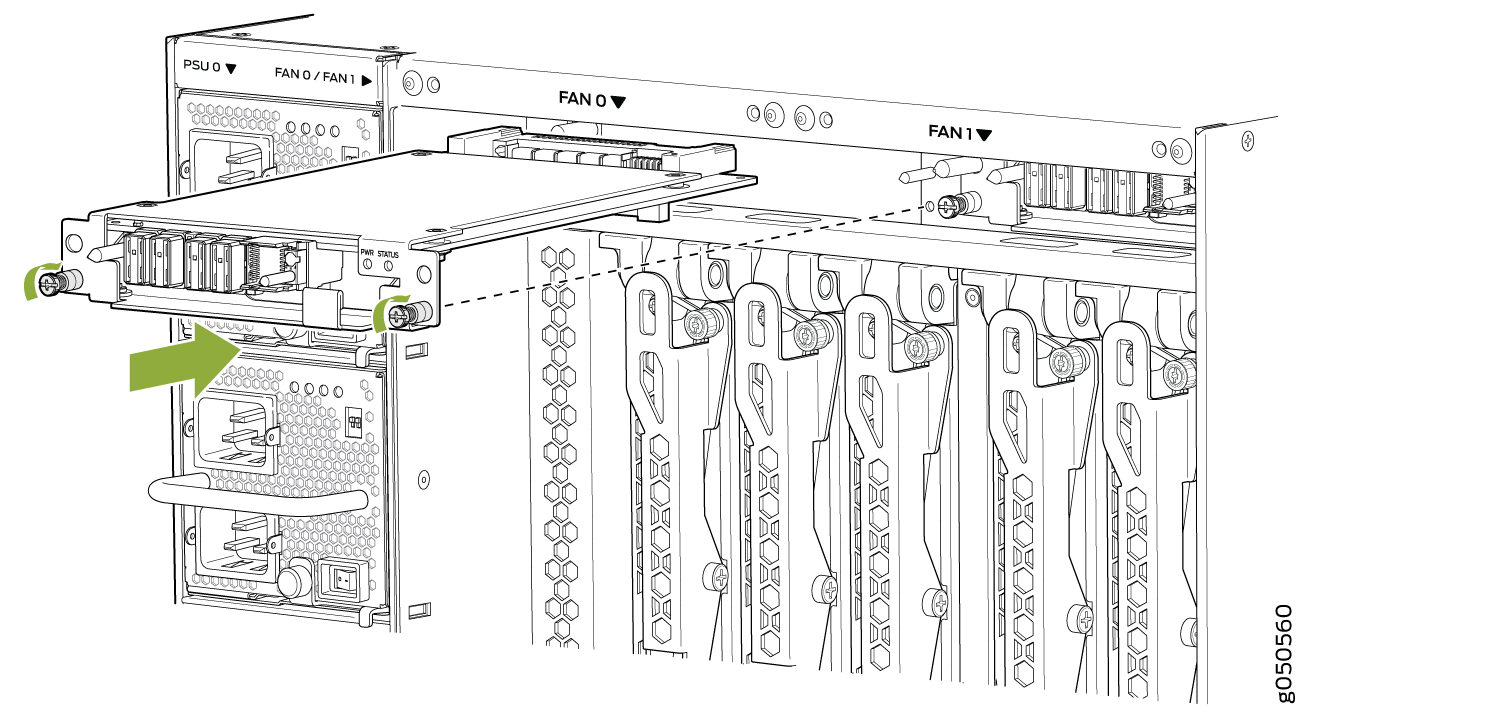
In order to install a fan tray controller, you must first remove the associated fan tray. With the fan tray removed, the fan tray controller is installed horizontally above the Switch Interface Boards (SIBs) at the top of the chassis.
Before you install a fan tray controller:
-
Ensure that you have removed the associated fan tray and fan tray controller. See Remove a PTX10008 Fan Tray and Remove a PTX10008 Fan Tray Controller.
-
Ensure that you understand how to prevent ESD damage. See Prevention of Electrostatic Discharge Damage.
-
Ensure that you have the following parts and tools available to install a fan tray controller into a PTX10008:
-
Electrostatic discharge (ESD) grounding strap
-
Replacement fan tray controller (JNP10008-FAN-CTRL, JNP10008-FTC2 or JNP10008-FTC3)
-
A Phillips (+) screwdriver, number 1, for the captive screws
-
To install a fan tray controller:
Remove a PTX10008 Fan Tray Controller
For each of the two fan trays, there is a fan tray controller. Each controller is a hot-removable and hot-insertable field-replaceable unit (FRU); you can remove and replace one fan tray controller while the router is running without turning off power to the router or disrupting routing functions. There are three models of fan tray controller:
-
JNP10008-FAN-CTRL, which supports fan tray JNP10008-FAN
-
JNP10008-FTC2, which supports fan tray JNP10008-FAN2
-
JNP10008-FTC3, which supports fan tray JNP10008-FAN3 and JNP10008-FAN2
See Figure 13 for the JNP10008-FAN-CTRL and Figure 14 for the JNP10008-FTC2.
Do not remove the fan tray controller unless you have a replacement controller available.
In order to access a fan tray controller, you must first remove the fan tray. With the fan tray removed, the fan tray controller is installed horizontally above the switch interface boards (SIBs) at the top of the chassis.
Before you remove a fan tray controller:
-
Ensure that you understand how to prevent ESD damage. See Prevention of Electrostatic Discharge Damage.
-
Ensure that you have the following parts and tools available to remove a fan tray controller from a PTX10008:
-
Electrostatic discharge (ESD) grounding strap
-
An electrostatic bag or an antistatic mat
-
Replacement fan tray controller
-
A Phillips (+) screwdriver, number 1, for the captive screws
-
Both models of fan controller are removed using the same procedure.