PTX10008 Routing and Control Board Components and Descriptions
The Routing and Control Board (RCB) is an integrated board and a single FRU that provides Routing Engine and Control Board (CB) functionality. The Routing Engine performs all route-processing functions, whereas the CB performs chassis control and management plane functionality. The RCB provides control plane functions. You can install one or two RCBs on the router. Each RCB functions as a unit.
PTX10008 Routing and Control Board Description
The PTX10008 Routing and Control Board (RCB) is responsible for system management in a PTX10008 (see Figure 1). The chassis can run with one or two RCBs. We ship the base configurations with one RCB; and you can expand the configuration with a second RCB for a fully-redundant system. When two RCBs are installed, one functions as the primary RCB and the second as a backup. If the primary RCB is removed, the backup RCB becomes the primary if GRES is configured.
PTX10008 routers support the following Routing Engines for systems running Junos OS:
-
JNP10K-RE0
-
JNP10K-RE1
-
JNP10K-RE1-LT
PTX10008 routers that have JNP10008-SF3 or JNP10008-SF5 installed support the following Routing Engines with Junos OS Evolved:
-
JNP10K-RE2-E, 128 gigabytes of memory (runs on Junos OS Evolved Release 25.4R1-S1 and later)
-
JNP10K-RE2-E-LT, 128 gigabytes of memory (runs on Junos OS Evolved Release 25.4R1-S1 and later)
-
JNP10K-RE2-E128 (128 GB, runs Junos OS Evolved Release 22.4R1 and later)
-
JNP10K-RE1-E128 (128 GB, runs Junos OS Evolved Release 19.4R1-S1 and later)
-
JNP10K-RE1-ELT (64 GB, runs limited Junos OS Evolved Release 20.3R1 and later)
-
JNP10K-RE1-E (64 GB, runs Junos OS Evolved Release 19.4R1-S1 and later)
If you have JNP10008-SF5 installed, we recommend that you use JNP10K-RE2-E128 or JNP10K-RE1-E128.
The two variants of JNP10K-RE3-E (JNP10K-RE3-E, JNP10K-RE3-E-LT) have the same form factor.
- Routing and Control Board Functions
- Routing and Control Board Components
- Routing and Control Board Physical Specifications
Routing and Control Board Functions
The Routing and Control Board integrates the control plane and Routing Engine functions into a single management unit. Each RCB provides all the functions needed to manage the operation of the modular chassis:
-
System control functions such as environmental monitoring
-
Routing Layer 2 and Layer 3 protocols
-
Communication to all components such as line cards, Switch Interface Boards (SIBs), and power and cooling
-
Transparent clocking
-
Alarm and logging functions
Routing and Control Board Components
Each RCB consists of the following internal components:
-
10 Core 3 GHz (JNP10K-RE3-E) or Quad-core 2.5-GHz CPU
-
128 GB SDRAM (JNP10K-RE3-E) or 32 GB SDRAM
-
2 x 400 G M.2 SSD (JNP10K-RE3-E) or SATA SSD
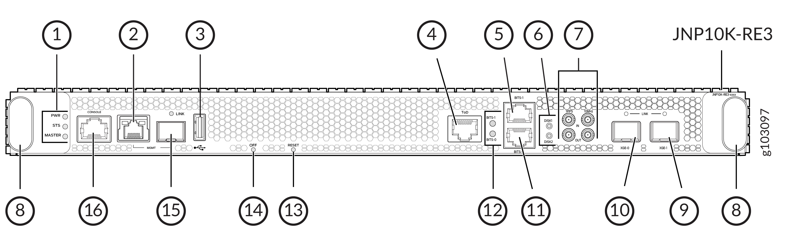
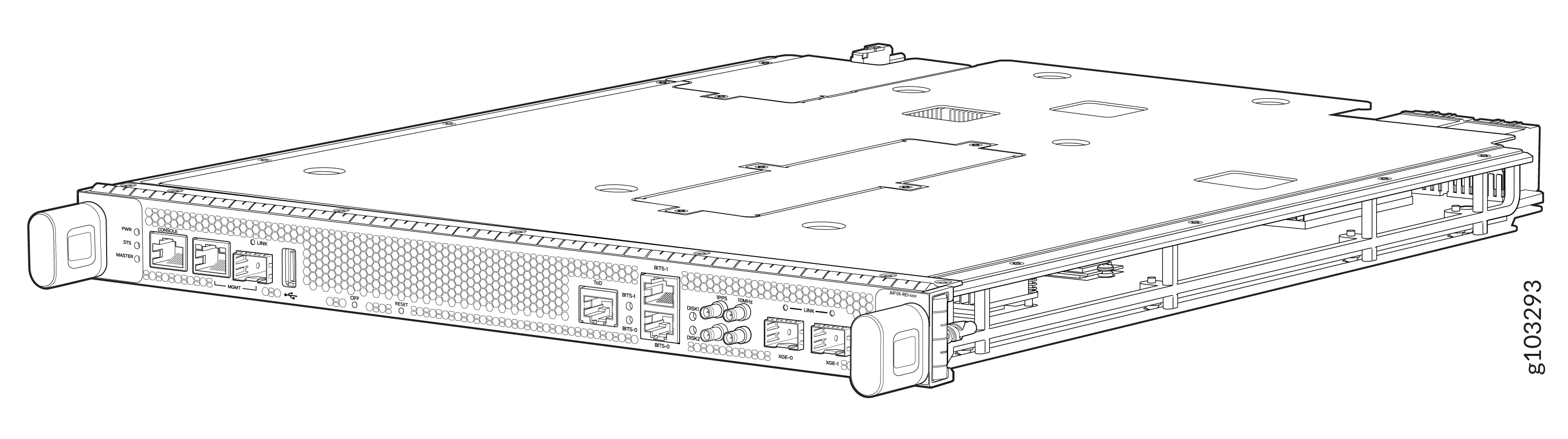
1 — RCB status LEDs | 9 — XGE-1 not used (reserved ports) |
2 — Management (MGMT) port | 10 — XGE-0 not used (reserved ports) |
3 — USB port | 11 — BITS0 clock port |
4 — ToD—Time-of-day (TOD) port | 12 — Clock LEDs |
5 — BITS1 clock port | 13 — Reset button |
6 — Solid State Disk (SSD) LEDs | 14 — Online/Offline button |
7 — GPS clock ports | 15 — Management (MGMT) port |
8 — Handles | 16 — Console (CONSOLE) port |
Other features are shown in Figure 5.
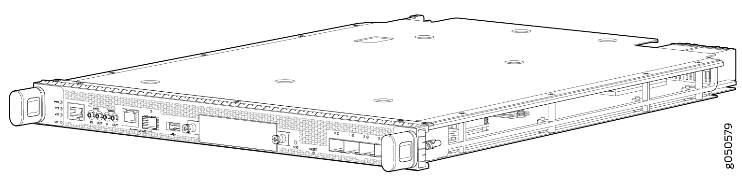
1 — RCB status LEDs | 5 — USB 2.0 port |
2 — Console (CON) port | 6 — Secondary 50-GB SATA SSD slot |
3 — PTP-capable connections: SMB In, SMB Out, 10 MHz In, 10 MHz Out | 7 — Reset (RESET) button |
4 — Ethernet management (MGMT) ports: RJ-45 port for 10/100/1000 BASE-T (em0) and small-form factor pluggable (SFP) for port fiber (em1). If both copper and fiber cables are installed, the RJ-45 is the default. | 8 — Four SFP+ ports (reserved for future use) |
You can use either management interface, em0 or em1 when the RCB is running as the primary RE. Use only em1 when the RCB is running as the backup RE.
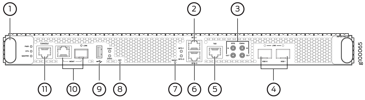
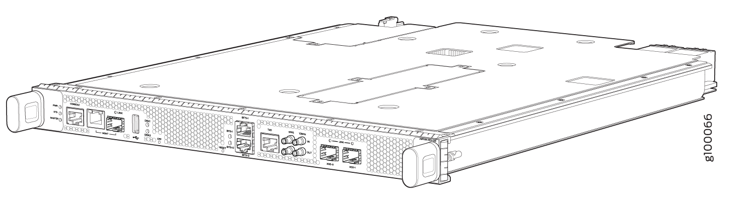
1 — Handles | 7 — Reset button |
2 — BITS-1 clock port | 8 — Online/Offline button |
3 — GPS clock ports (1PPS and 10MHz) | 9 — USB port |
4 — XGE-0 and XGE-1 not used (reserved ports) | 10 — Management (MGMT) ports |
5 — ToD—Time-of-day (TOD) port | 11 — Console (CONSOLE) port |
6 — BITS-0 clock port |
Routing and Control Board Physical Specifications
All the RCBs have the same physical specifications. Table 1 shows the physical specifications of the RCBs.
|
Height |
Width |
Depth |
Weight |
|---|---|---|---|
|
1.3 in. (3.3 cm) |
15.05 in. (38.2 cm) |
18.96 in. (48.2 cm) |
12.2 lb (5.54 kg) |
PTX10008 Routing and Control Board LEDs
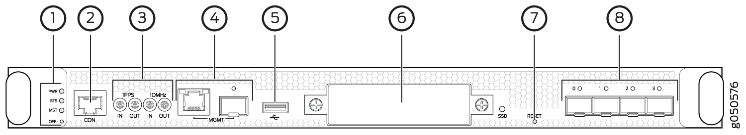
The PTX10008 Routing and Control Boards (RCBs) have various types of LED indicators (see Figure 7).
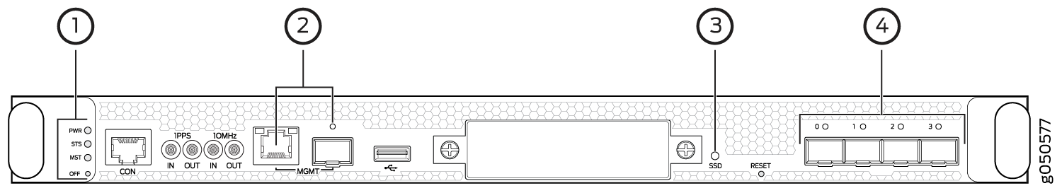
1 — RCB status panel LEDs | 3 — SATA SSD |
2 — Management ports and LED | 4 — Virtual port connection |
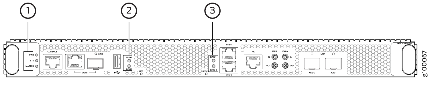
1 — RCB status panel LEDs | 3 — Clock LEDs—BITS-0 and BITS-1 |
2 — SSD LEDs—DISK1 and DISK2 |
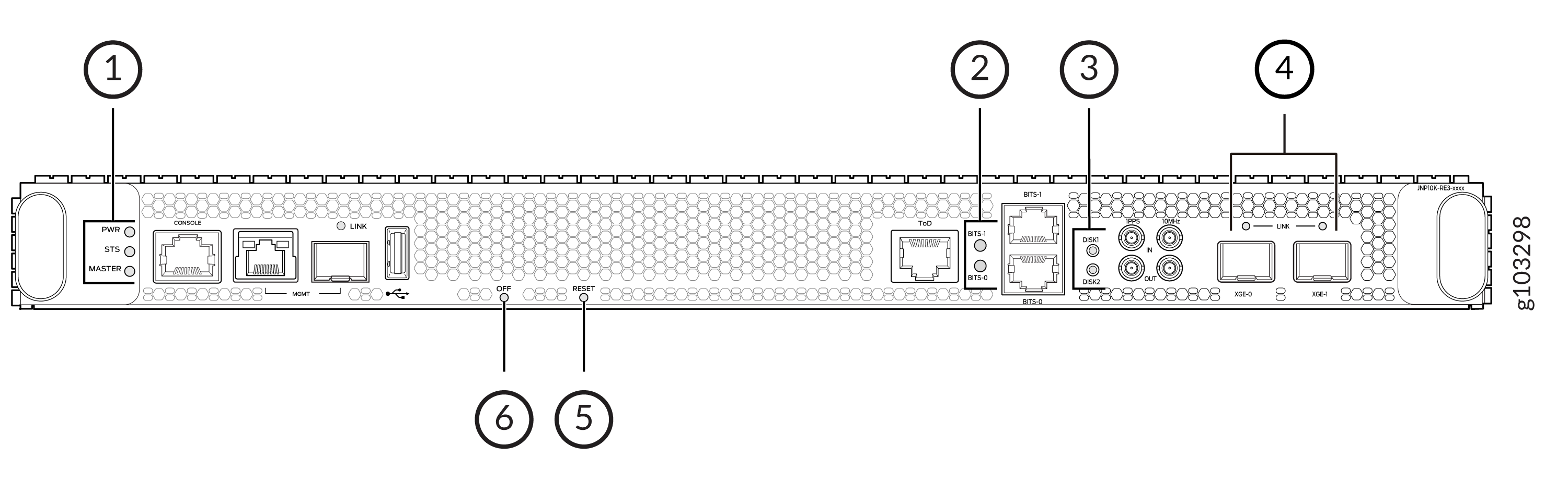
1 — RCB status panel LEDs | 4 — Link status LEDs for XGE-0 and XGE-1 ports |
2 — Clock LEDs–BITS-0, and BITS-1 | 5 — Reset button with LED |
3 — Solid State Disk (SSD) LEDs—DISK1 and DISK2 | 6 — On/Off button with LED |
- Routing and Control Board Status Panel LEDs
- PTX10008 Management Port LEDs
- SATA SSD LEDs
- Clock LEDs (JNP10K-RE1, JNP10K-RE1-LT, JNP10K-RE1-E128, JNP10K-RE2-E128, JNP10K-RE3-E, and JNP10K-RE3-E-LT)
Routing and Control Board Status Panel LEDs
The RCB status panel LEDs indicate the state of the RCB (see Figure 10).
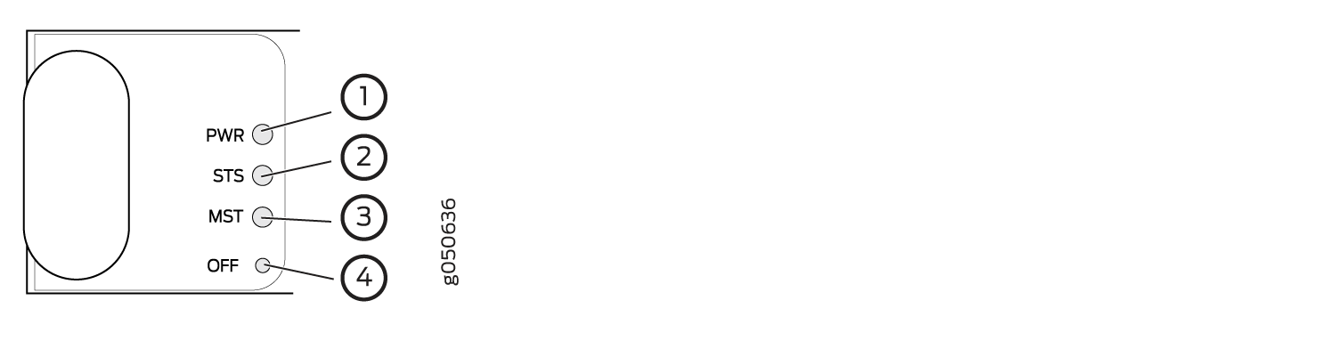
1 — Power (PWR) LED | 3 — Primary (MST) LED |
2 — Status (STS) LED | 4 — Offline (OFF) button |
Table 2 describes the LEDs on the RCB status panel.
|
LED |
Color |
State |
Description |
|---|---|---|---|
|
PWR (Power) |
Green |
On steadily |
The RCB is receiving adequate power. |
|
Yellow |
Blinking |
The RCB has detected an error. |
|
|
None |
Unlit |
The RCB is not powered up. |
|
|
STS (Status) |
Green |
On steadily |
The RCB is online and functioning correctly. |
|
Green |
Blinking |
The beacon feature is enabled. |
|
|
Yellow |
Blinking |
The RCB has detected an error. |
|
|
None |
Unlit |
The RCB is not receiving power. |
|
|
MST (Primary) |
Green |
On steadily |
The RCB is the primary RCB. |
|
None |
Unlit |
The RCB is the backup RCB. |
PTX10008 Management Port LEDs
The two management ports on the RCB of a PTX10008 router have LEDs that indicate link status and link activity. These two ports, located on the RCB panel between the clocking connections and the USB port, are both labeled MGMT. The left management port (RJ-45) is for 10/100/1000 BASE-T connections, and the right port (SFP) is for 10/100/1000 BASE-T and small form-factor pluggable (SFP) 1000 BASE-X connections (see Figure 11). The copper (RJ-45) port has separate LEDs for status and activity. The fiber (SFP) port has a combination link and activity LED.
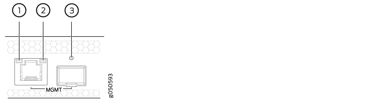
1 — Status LED (RJ-45) | 3 — Link/activity/status LED (SFP)) |
2 — Activity LED (RJ-45) |
Table 3 describes the RJ-45 management port LEDs, and Table 4 describes the SFP status LEDs.
|
LED |
Color |
State |
Description |
|---|---|---|---|
|
Port speed |
Unlit |
Off |
The port speed is 10 MB. |
|
Green |
Blinking |
The port speed is 100 MB. |
|
|
Green |
On steadily |
The port speed is 1000 MB. |
|
|
Link/Activity/Status |
Unlit |
Off |
No link is established, there is a fault, or the link is down. |
|
Green |
On steadily |
A link is established. |
|
|
Blinking |
There is link activity. |
||
|
Yellow |
Blinking or flickering |
The beacon feature is enabled. |
|
LED |
Color |
State |
Description |
|---|---|---|---|
|
Link/Activity/Status |
Unlit |
Off |
No transceiver is present. |
|
Green |
On steadily |
A link is established. The interface is up. |
|
|
Green |
Blinking or flickering |
The beacon feature is enabled. |
|
|
Yellow |
Blinking |
An error has occurred. |
XGE0 and XGE1 are not used.
SATA SSD LEDs
The Serial Advanced Technology Attachment (SATA) solid-state drive (SSD) LEDs indicate the status of the secondary drive.
Table 5 describes the LEDs for the secondary SATA drive.
|
LED |
Color |
State |
Description |
|---|---|---|---|
|
SSD on JNP10K-RE0 DISK1 and DISK2 on JNP10K-RE1 |
Green |
On steadily |
A SATA drive is present. |
|
Green |
Blinking |
The drive is active. |
|
|
Yellow |
On steadily |
The drive is active. |
|
|
Dark |
Unlit |
A drive is not installed. |
Clock LEDs (JNP10K-RE1, JNP10K-RE1-LT, JNP10K-RE1-E128, JNP10K-RE2-E128, JNP10K-RE3-E, and JNP10K-RE3-E-LT)
The clock LEDs indicate whether clocking is active.
Table 6 describes the BITS LEDs starting in Junos Evolved 21.4 R1.
Table 7 describes the clock LEDs in releases earlier than Junos Evolved 21.4 R1.
|
LEDs |
Color/State |
Description |
|---|---|---|
|
Clock LEDs—BITS-0 and BITS-1 |
Green |
The clock synchronization source is configured and qualified, the clock synchronization output is configured, and the output is active. |
|
The clock synchronization source is not configured but the clock synchronization output is configured and active. |
||
|
The clock synchronization source is configured and qualified but the clock synchronization output is not configured. |
||
|
Red |
The clock synchronization source is configured and qualified, and the output is active and is in holdover state. |
|
|
The clock synchronization source is not configured, but the output is active and is in holdover state. |
||
|
The clock synchronization source is configured, but has failed. |
||
|
The TX status is in squelched mode. |
||
|
Off |
Both the clock synchronization source and the clock synchronization output are not configured. |
|
LEDs |
Color |
State |
Description |
|---|---|---|---|
|
Clock LEDs—BITS-0 and BITS-1 |
Red |
Off |
Clock is active. |
|
On steadily |
Clock is not working. |