Install and Remove PTX10008 Routing and Control Boards
We ship PTX10008 routers with one or two Routing and Control Boards (RCBs) preinstalled in the chassis, depending on the configuration. You can install RCBs in the two top slots on the front of the chassis.
When you power on a router with a single RCB preinstalled in it, the RCB comes online as the primary and powers on the line cards and the switch fabric. If you install the second RCB, it powers up and the Routing Engine comes online in the backup mode; you must bring the control board of that RCB online by using the request chassis cb online command.
When you power on a router with two RCBs installed in it for the first
time, the RCB installed in slot CB 0
comes online as the primary (RE0 in the CLI)
and powers on the line cards and the switch fabric, and the RCB
installed in slot CB 1 comes online as
the backup (RE1 in the CLI) by default. You can
change this configuration by using the CLI. If you replace an
RCB, it powers up and the Routing Engine comes online in the
backup mode; you must bring the control board of that RCB online
by using the request chassis cb
online command.
To install or remove an RCB, read the following sections.
Install a PTX10008 Routing and Control Board
In redundant configurations, a PTX10008 RCB is a hot-removable and hot-insertable field-replaceable unit (FRU). In base configurations, you need to install a second RCB before removing a failing RCB in order to prevent the router from shutting down.
Before you install an RCB, ensure that you have an electrostatic discharge (ESD) grounding strap.
To install an RCB:
- Wrap and fasten one end of the ESD grounding strap around
your bare wrist and connect the other end of the strap to one of the
ESD points on the chassis (see Figure 1).Figure 1: ESD Point on the Front of the PTX10008 Chassis
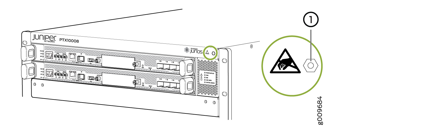 1—
1—ESD point
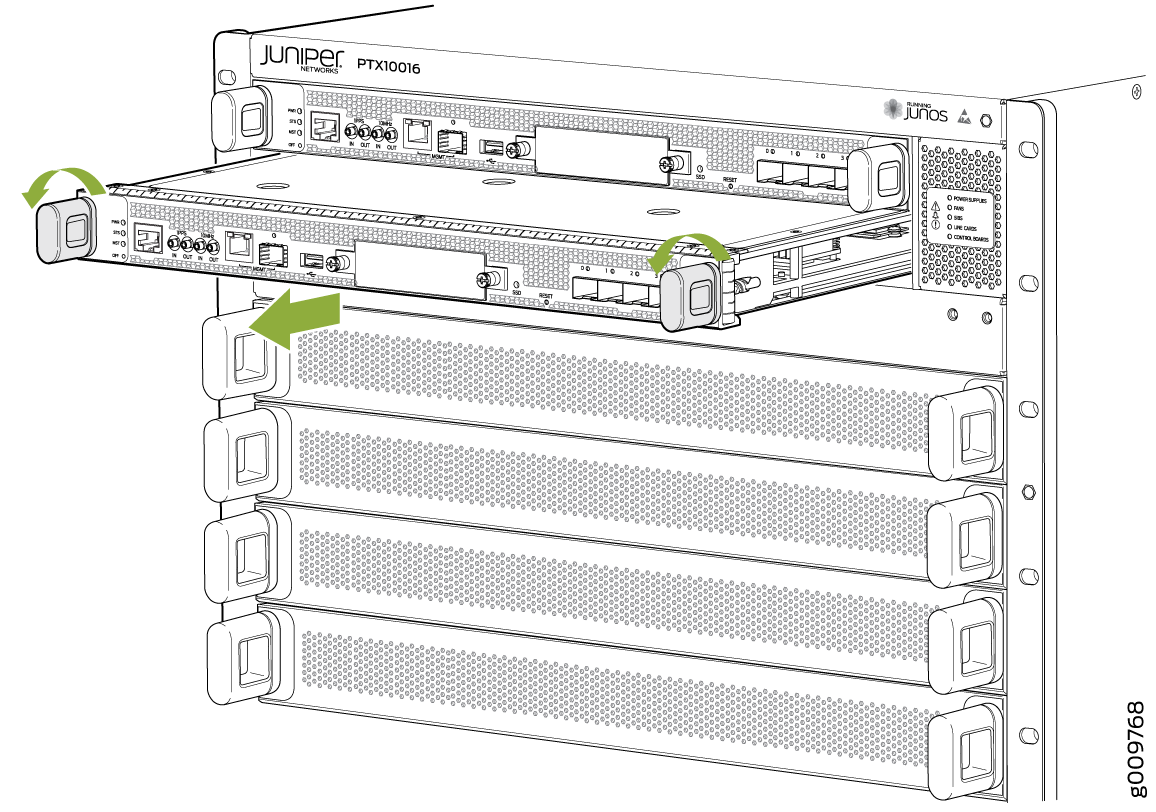
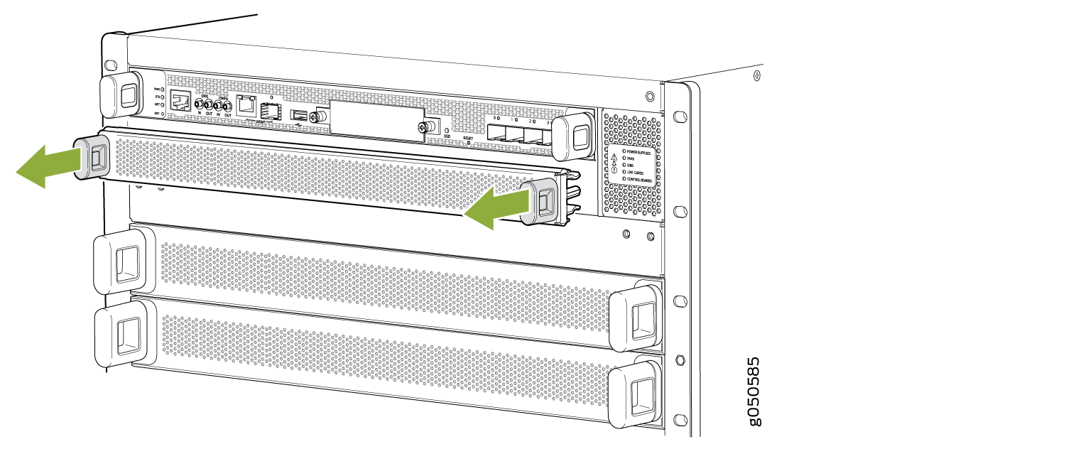
- Either remove the cover from the available RCB slot (see Figure 2) or remove the failing RCB (see Remove a PTX10008 Routing and Control Board).Figure 2: Remove an RCB Cover
- Grasp both handles on the RCB and rotate them simultaneously
clockwise until the RCB is fully seated and the handles are vertical
(see Figure 4). Figure 3: Installing JNP10K-RE3-E Routing and Control Board
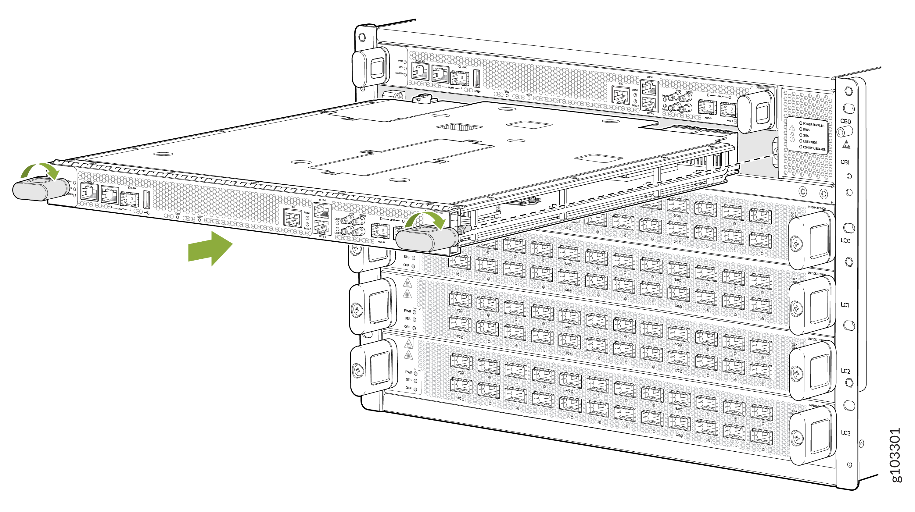 Figure 4: Install JNP10K-RE1-E or JNP10K-RE2-E RCB
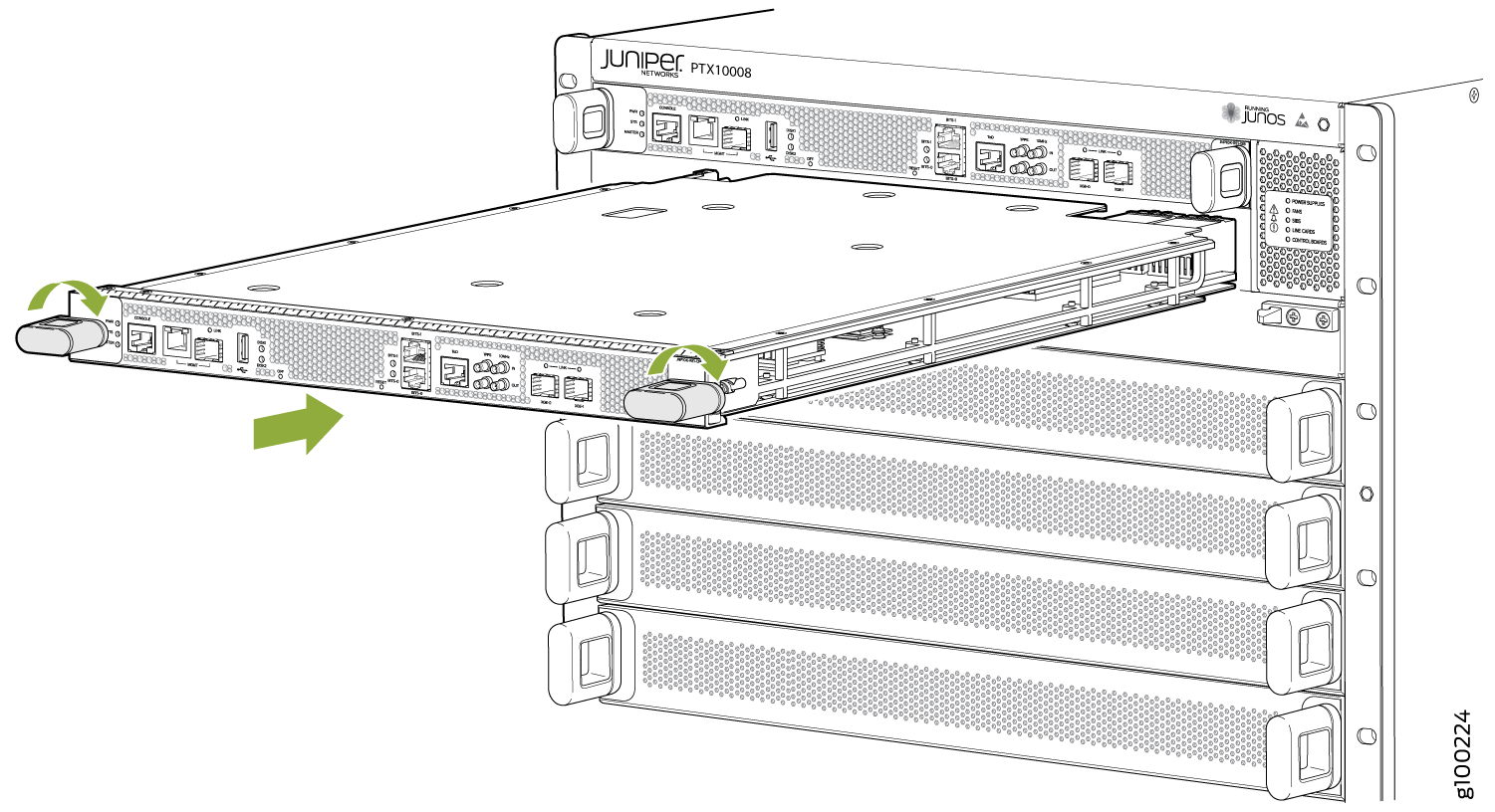
The RCB begins the power-on sequence when fully seated.
See Also
Remove a PTX10008 Routing and Control Board
In redundant configurations, a PTX10008 RCB is a hot-removable and hot-insertable field-replaceable unit (FRU). In base configurations, you need to install a second RCB before removing a failing RCB in order to prevent the router from shutting down. We recommend that you take base systems offline before replacing the RCB.
Before you remove a RCB, ensure that you have an electrostatic discharge (ESD) grounding strap.
In base configurations, removal of the RCB causes the system to shut down. In redundant configurations, removal of the RCB causes the system to reboot and start the election process for a new primary.
To remove a RCB:
- Wrap and fasten one end of the ESD grounding strap around
your bare wrist and connect the other end of the strap to one of the
ESD points on the chassis (see Figure 5).Figure 5: ESD Point on the Front of the PTX10008 Chassis1—
ESD point
- Grasp the handles and slide the RCB about halfway out
of the chassis (see Figure 7).Figure 6: Removing JNP10K-RE3-E Routing and Control Board
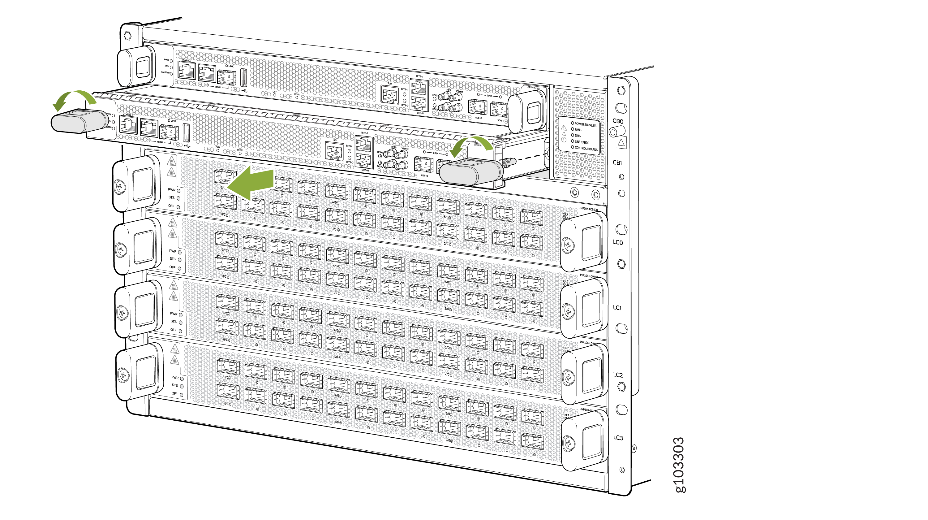 Figure 7: Removing JNP10K-RE1-E or JNP10K-RE2-E RCB