Install and Remove PTX10008 Switch Fabric Components
Each PTX10008 router contains five or six Switch Interface Boards (SIBs) that are installed vertically, mid-chassis, between the line cards and the Routing and Control Boards (RCBs) in the front and the fan trays in the rear. To install or remove the switch interface boards in a PTX10008 router, read the following sections.
How to Handle and Store PTX10008 Line Cards, RCBs, and SIBs
The PTX10008 chassis have several field-replaceable units (FRUs) that have fragile components. To avoid damaging the line cards, Routing and Control Boards (RCBs), and Switch Interface Boards (SIBs), be sure you follow the following safe handling practices.
How to Hold Line Cards and RCBs
Pay proper attention to the way you are holding line cards and RCBs. Line cards and RCBs are installed horizontally and it is best to hold them by the sides of the units when they are not in the chassis.
When walking with a line card or RCB:
- Take care not to strike the unit against any object as
you carry it.CAUTION:
Never hold the line card or RCB by the connector edge. The connectors are fragile and the line card or RCB will not seat properly if the connector is damaged. See Figure 1.
Figure 1: Connector Edge of a Line Card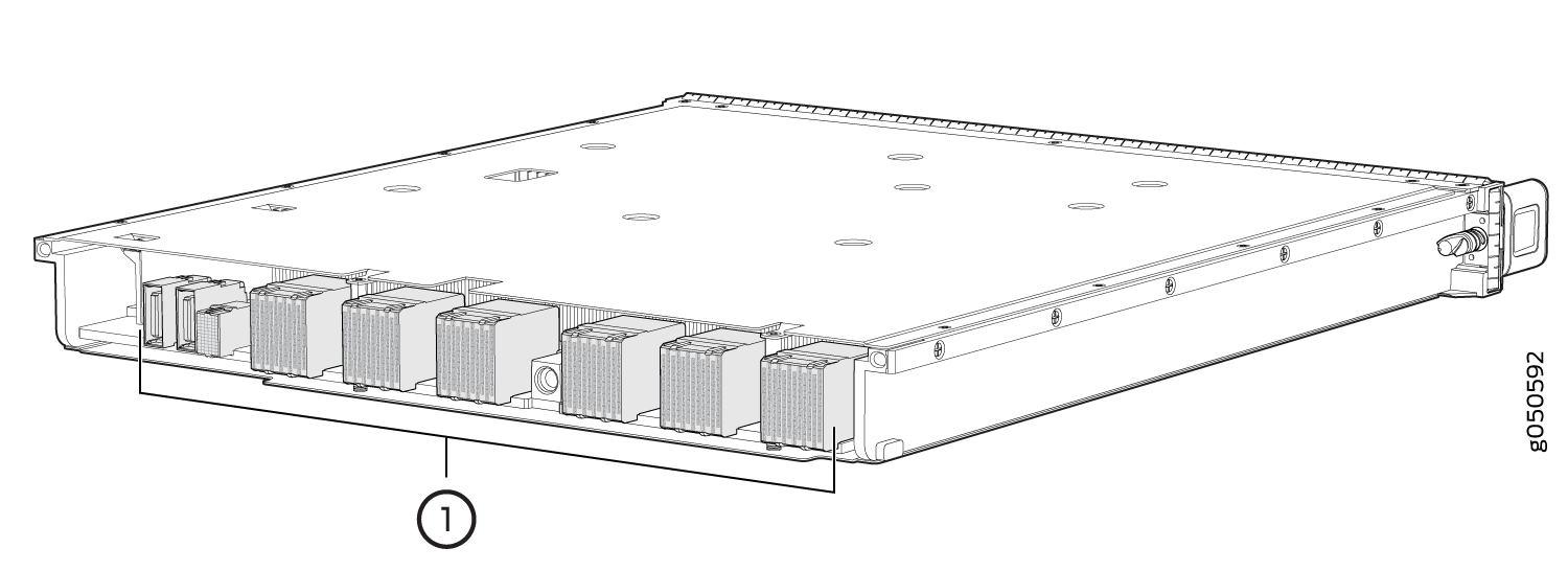 1—
1—Connectors
How to Hold SIBs
SIBs are installed vertically and should be held vertically until they are clear of the router before rotating them 90 degrees and placing them on an antistatic mat or placing them in an antistatic bag for storage. See Figure 2, Figure 3, and Figure 4.
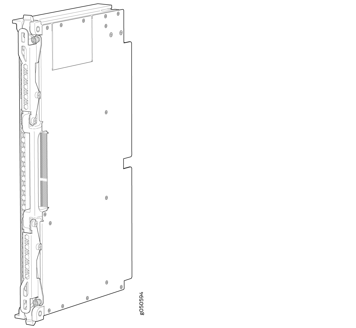
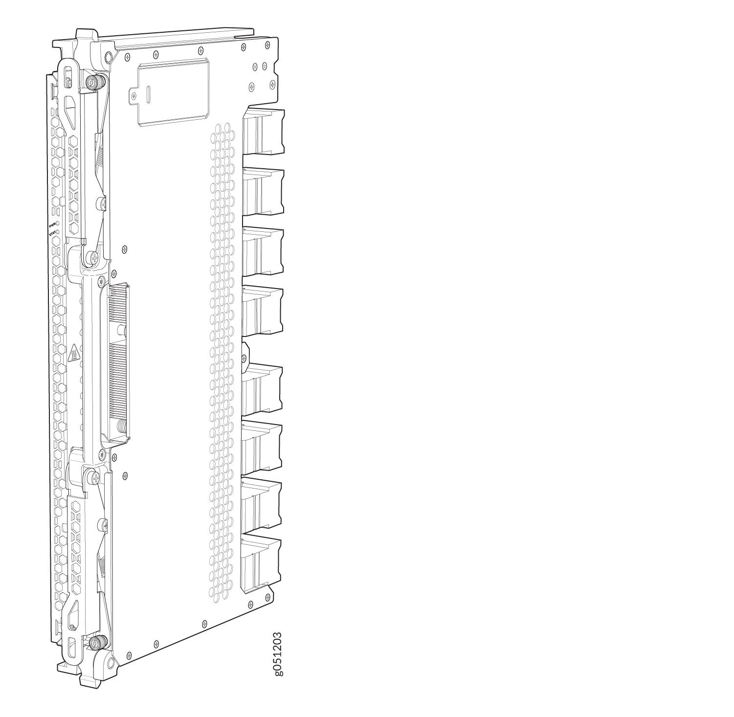
The proper method of holding a SIB is to:
How to Store Line Cards, RCBs, and SIBs
You must store line cards, RCBs, and SIBs either in the chassis or in a spare shipping container, horizontally and sheet metal side down. Do not stack these units on top of one another or on top of any other component. Place each unit separately in an antistatic bag or on an antistatic mat placed on a flat, stable surface.
Because these units are heavy, and because antistatic bags are fragile, inserting the line card into the bag is best done with two people.
To insert a line card, RCB, or SIB into an antistatic bag:
- Hold the unit horizontally with the faceplate toward you.
- Slide the opening of the bag over the connector edge.
If you must insert the line card, RCB, or SIB into a bag by yourself:
Lay the unit horizontally on an antistatic mat that is on a flat, stable surface with the sheet metal side down.
Orient the unit with the faceplate toward you.
Carefully insert the connector edge into the opening of the bag and pull the bag toward you to cover the unit.
Install a PTX10008 Switch Interface Board
A PTX10008 router has up to six Switch Interface Boards (SIBs) that are located in the middle of the chassis behind the fan trays. SIB 0 through SIB 2 are located behind the left fan tray, and SIB 3 through SIB 5 are located behind the right fan tray. You must remove the appropriate fan tray to install a SIB. See Remove a PTX10008 Fan Tray. You must not install different types of SIBs in the same chassis.
Ensure you have the following equipment with you before installing a SIB:
Antistatic bag or antistatic mat
Electrostatic discharge (ESD) grounding strap
To install a SIB:
- Wrap and fasten one end of the ESD grounding strap around
your bare wrist and connect the other end of the strap to an ESD point
on the chassis. There is an ESD point located next to the protective
earthing terminal and below PSU 5 on the
rear of the PTX10008 (see Figure 5).Figure 5: ESD Point on the Rear of the PTX10008
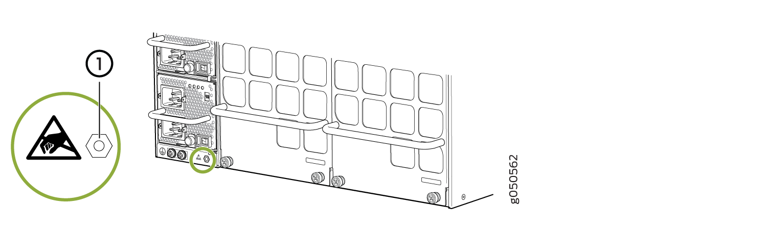 1—
1—ESD point
-
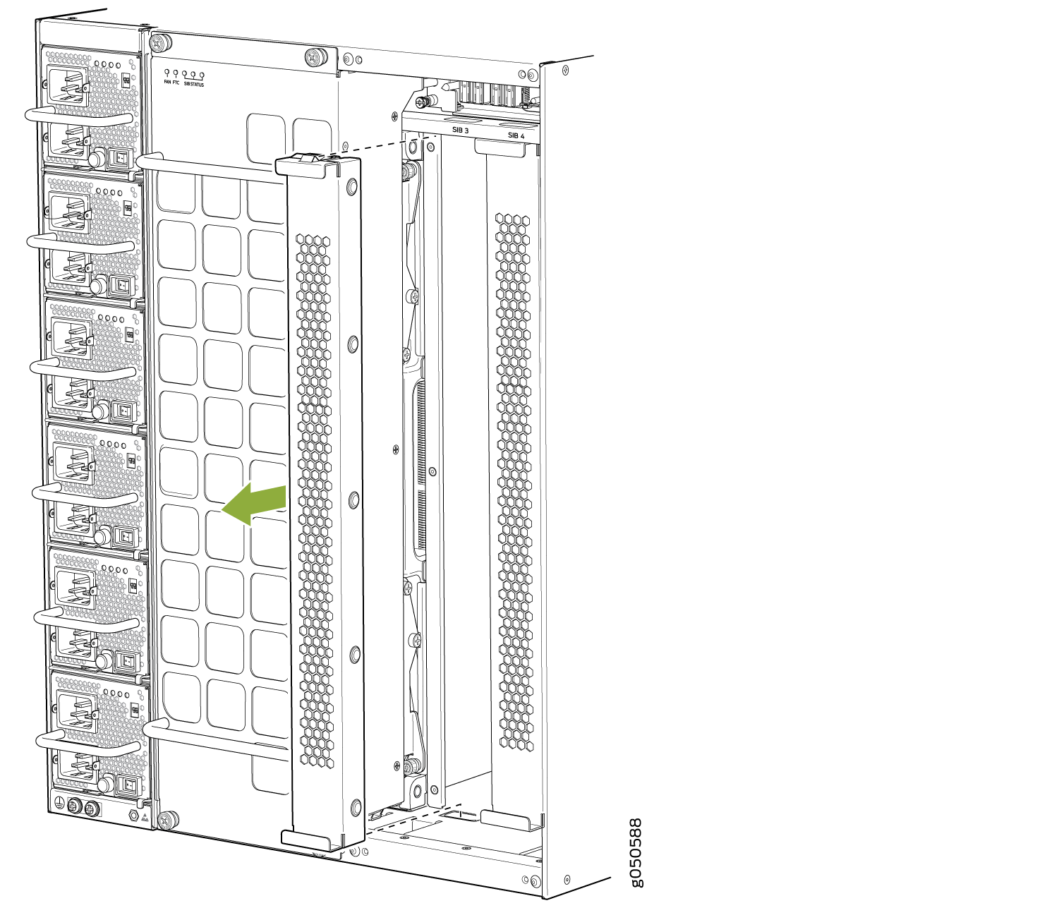
Either remove the SIB (see Remove a PTX10008 Switch Interface Board) or remove the cover by
grasping each side of the plate and pulling straight out (see Figure 6.
Figure 6: Remove a SIB Cover on a PTX10008
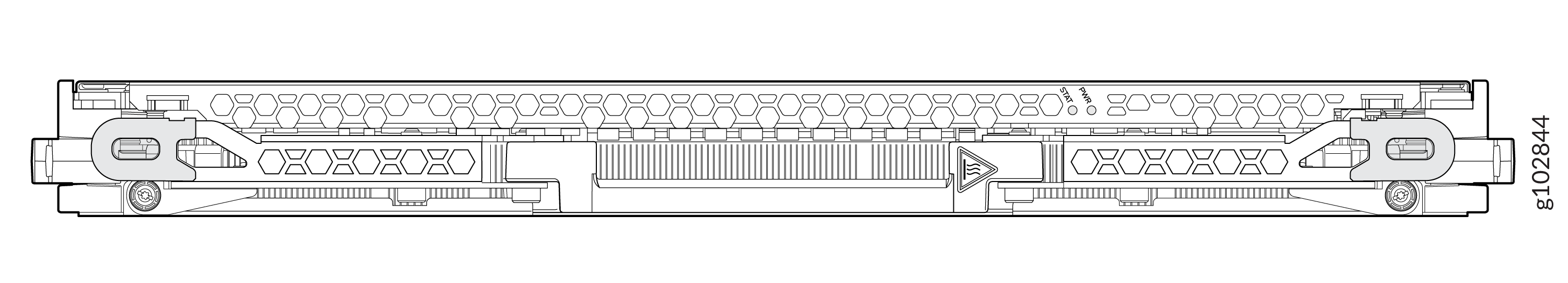
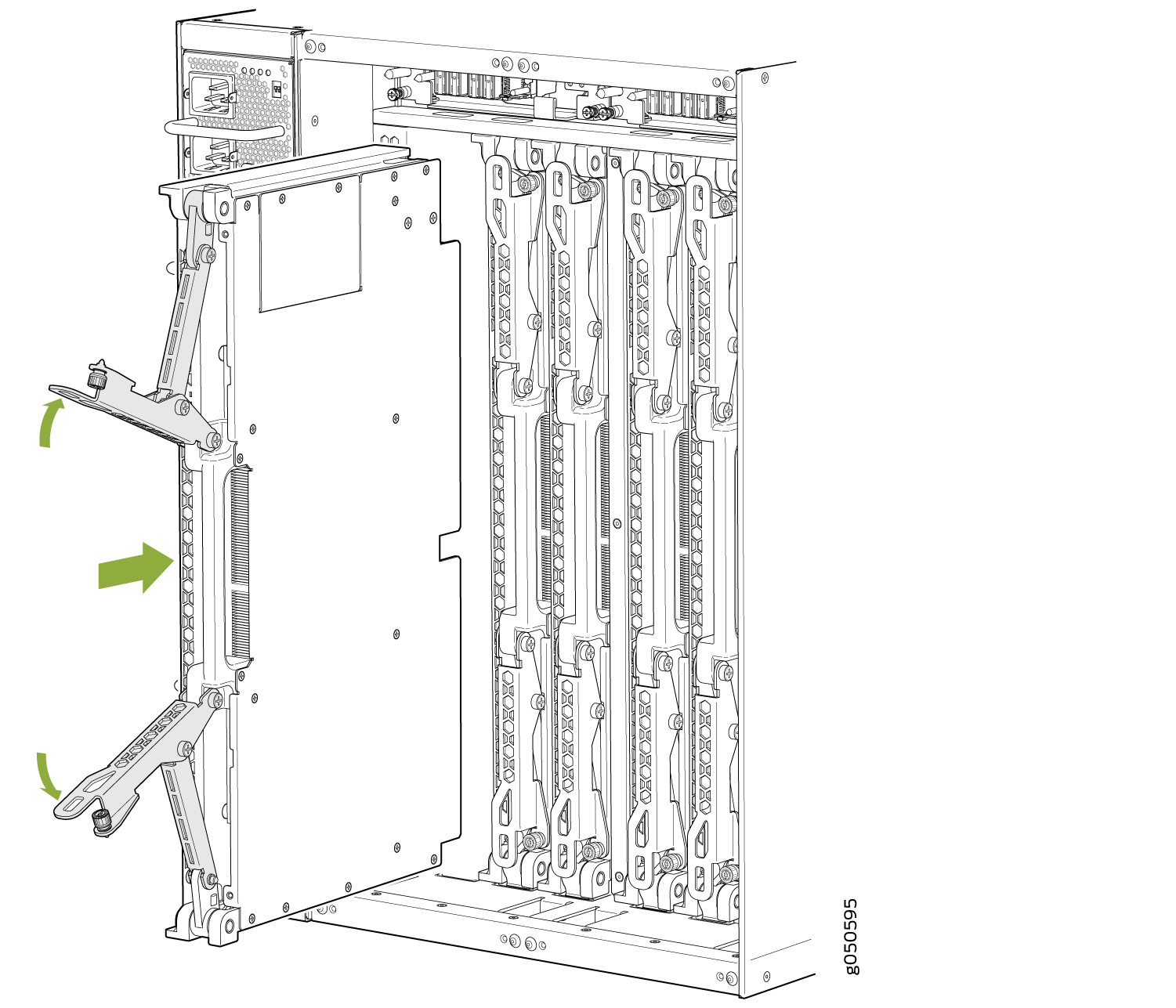
- Grasp the two ejector handles and fold them inward until
they latch to seat the SIB (see Figure 7 for the PTX10008).Figure 7: Install a PTX10008 SIB
Remove a PTX10008 Switch Interface Board
A PTX10008 router has up to six Switch Interface Boards (SIBs) that are located in the middle of the chassis behind the fan trays. SIB 0 through SIB 2 are located behind the left fan tray and SIB 3 through SIB 5 are located behind the right fan tray. You must remove the appropriate fan tray to access the failing SIB. See Remove a PTX10008 Fan Tray.
Ensure you have the following equipment on hand before replacing a SIB:
Two antistatic bags or antistatic mats
Electrostatic discharge (ESD) grounding strap
To remove a SIB (see Figure 10):
- Wrap and fasten one end of the ESD grounding strap around
your bare wrist and connect the other end of the strap to an ESD point
on the chassis. There is an ESD point located next to the protective
earthing terminal and below PSU 5 on the
rear of the PTX10008 (see Figure 8).Figure 8: ESD Point on Rear of the PTX100081—
ESD point
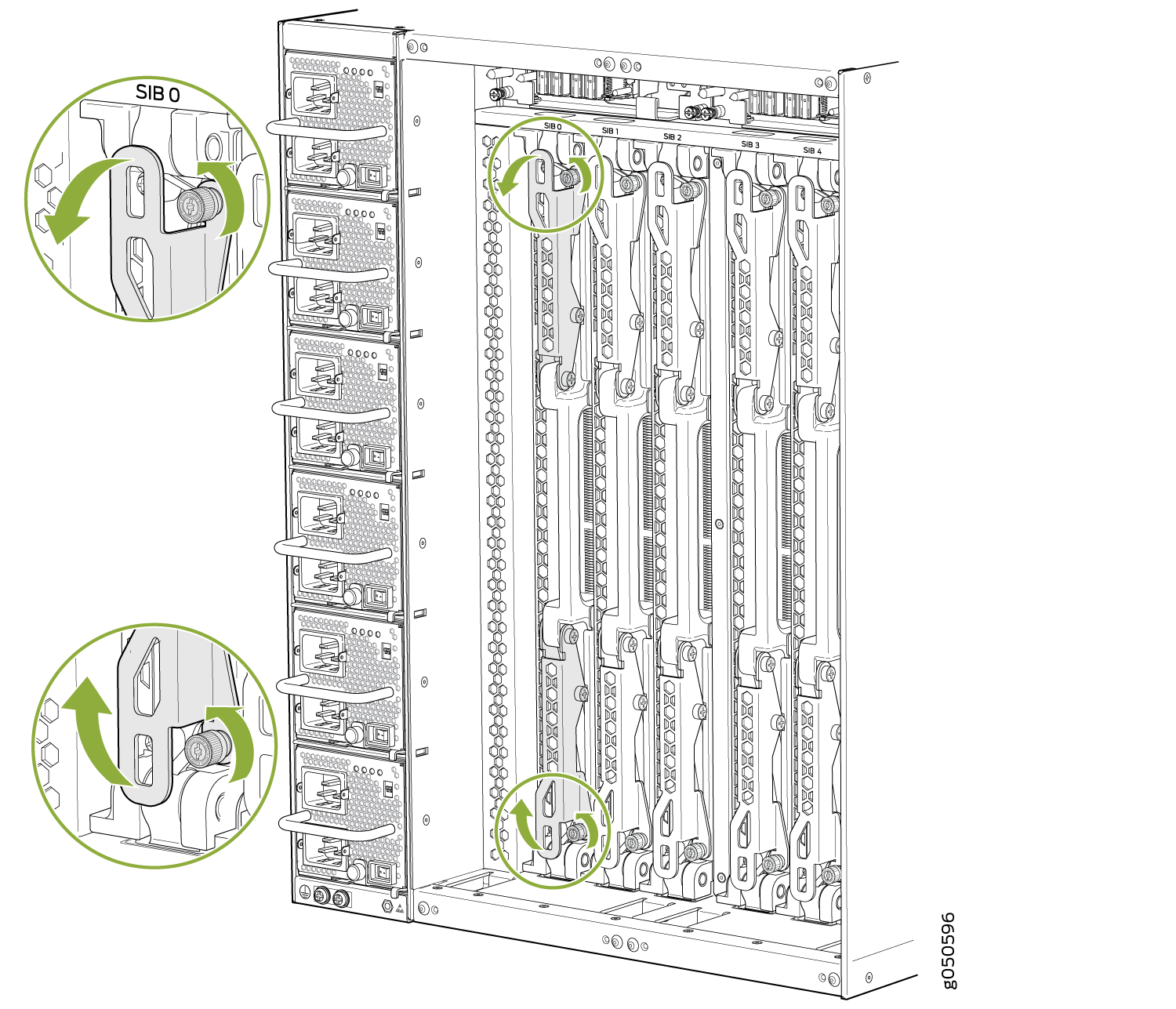
- Grasp both ejector handles and spread them apart. The
SIB slides about a quarter of the way out of the slot. See Figure 9.Figure 9: Loosen the Captive Screws and Spread the Ejector Handles
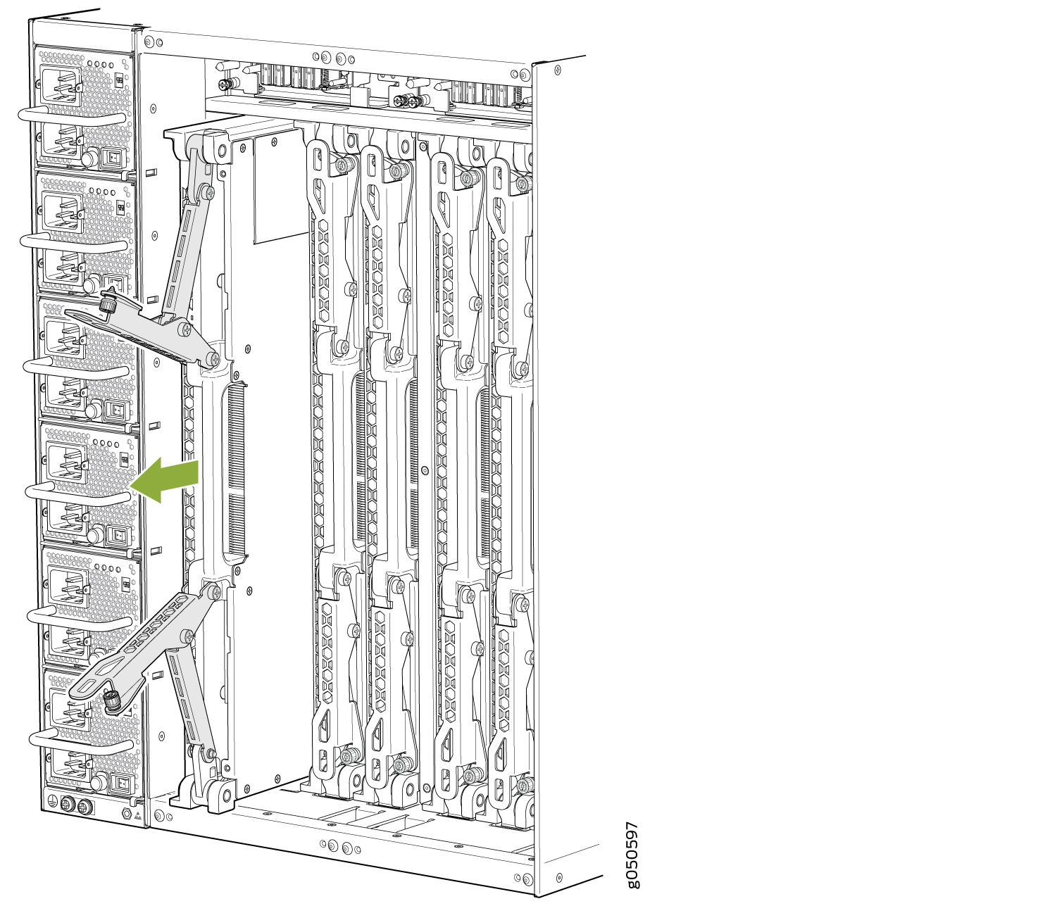
- Grasp the ejector handle with one hand and place your
other hand under the SIB for support as you slide the SIB out of the
slot (see Figure 10).Figure 10: Removing the SIB from a PTX10008 Chassis
- Support the SIB as you rotate the SIB 90 degrees and place
it on the antistatic mat with the printed circuit board (PCB) facing
upward. Be careful not to bump or handle the SIB by the connectors.
If you do not have an antistatic mat, have another person help you
slide the antistatic bag over the SIB before placing it on a stable
surface. See Figure 11.CAUTION:
Do not stack hardware components on top of one another after you remove them. Place each component on an antistatic mat resting on a stable, flat surface.
Figure 11: Extracted SIB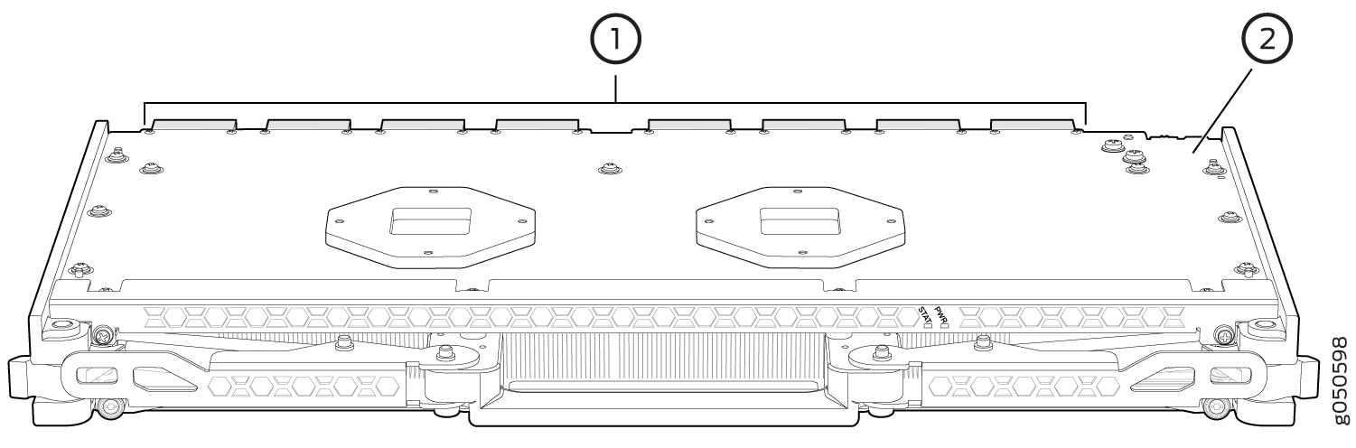 1—
1—Connectors
2—Printed circuit board