ON THIS PAGE
Replacing an MX2000 Three-Phase Delta AC Power Distribution Module
Replacing an MX2020 Three-Phase Wye AC Power Distribution Module
Replacing an MX2008 DC Power Distribution Module Cable (-48 V)
Replacing an MX2000 DC Power Distribution Module (240 V China)
Replacing an MX2000 High-Voltage Second-Generation Universal (HVAC/HVDC) Power Supply Module
Replacing an MX2000 High-Voltage Universal (HVAC/HVDC) Power Distribution Module
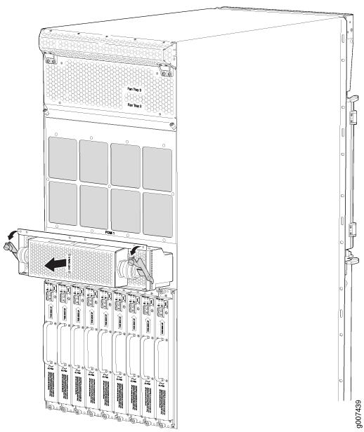
Maintaining MX2008 Power System Components
Replacing an MX2008 AC Power Supply Module
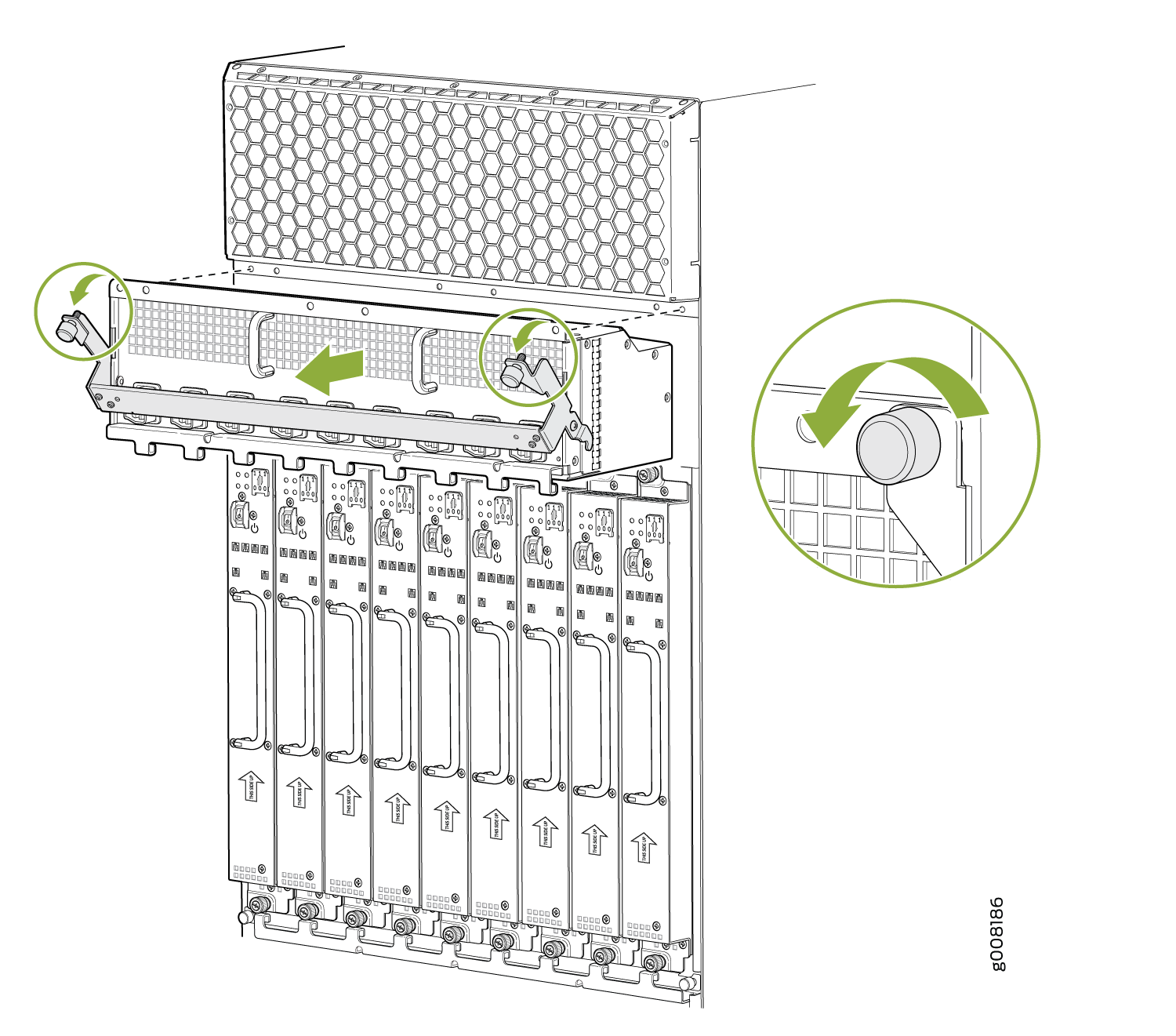
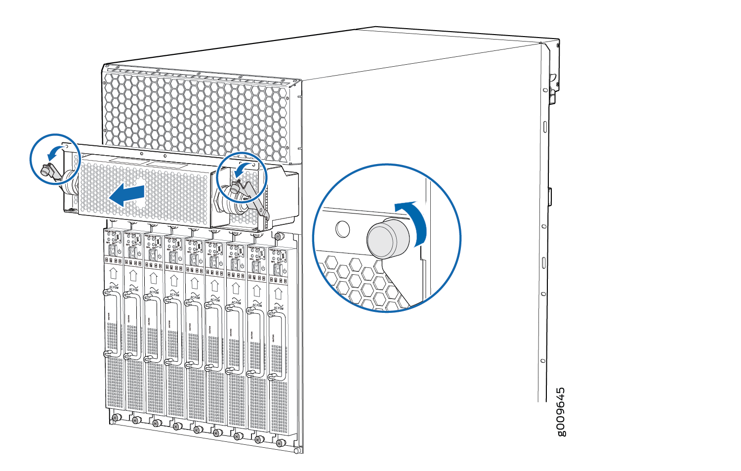
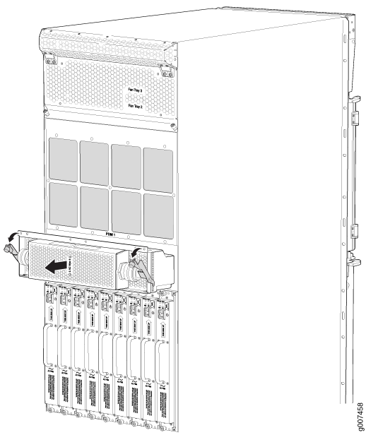
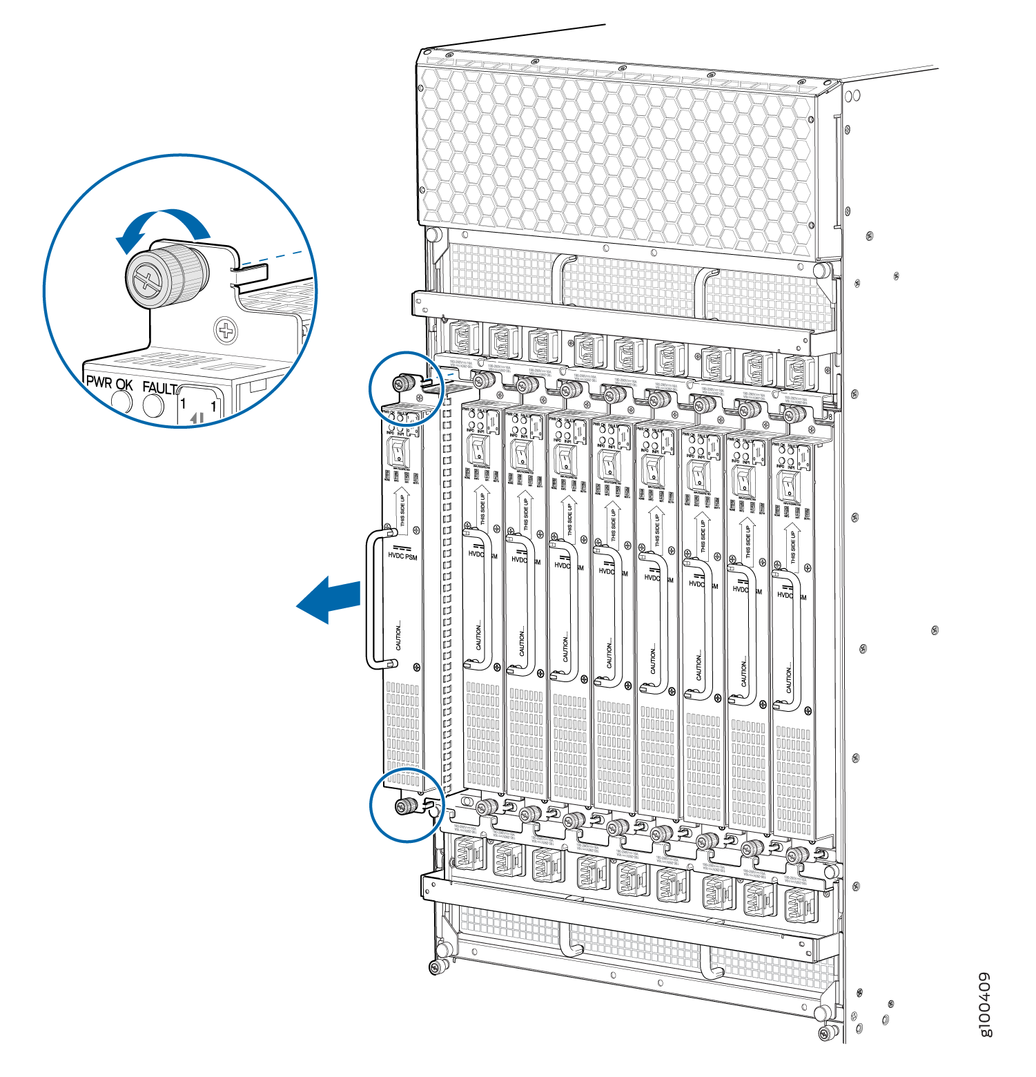
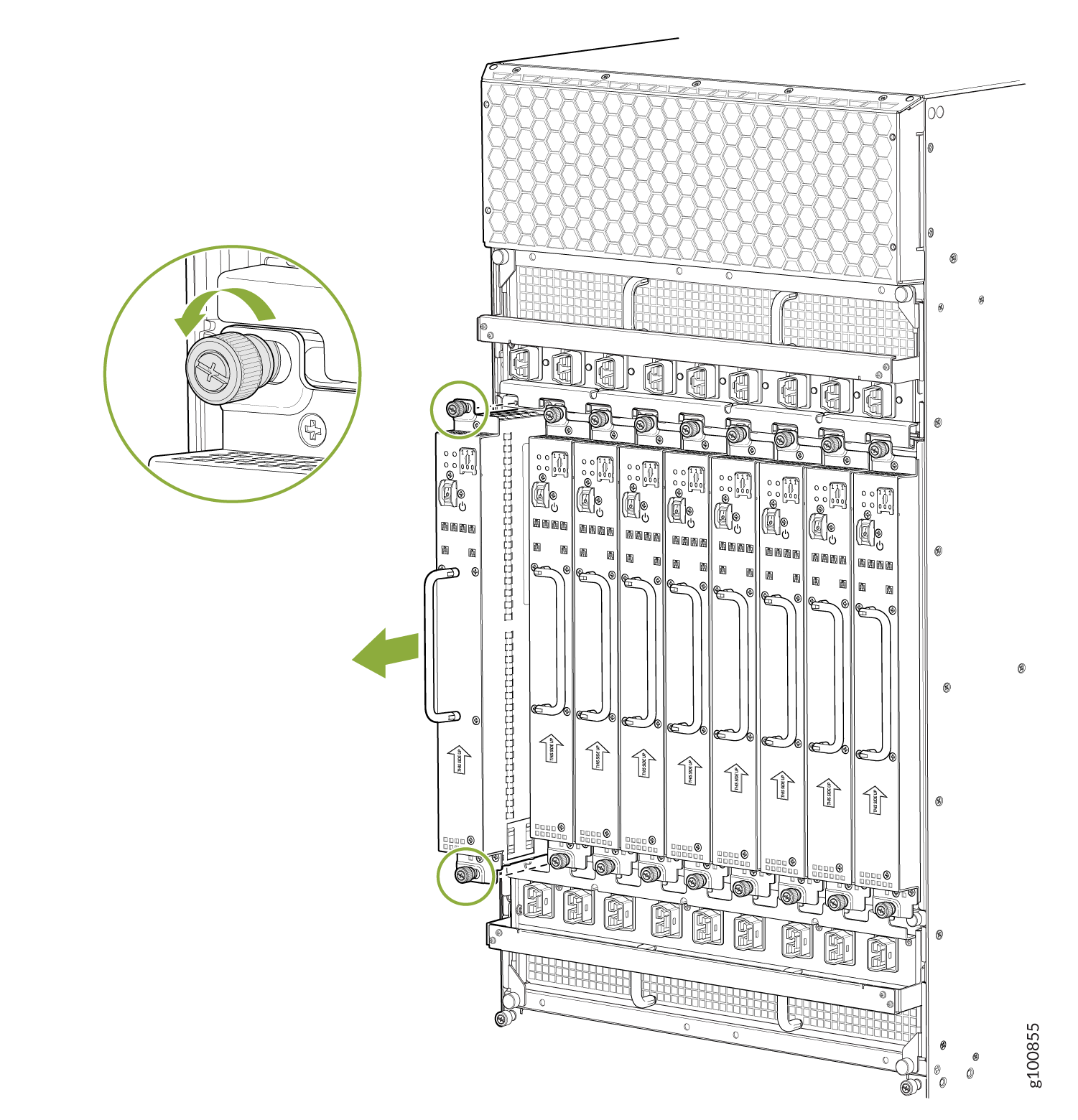
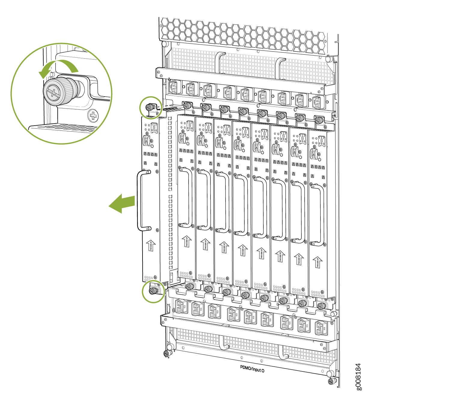
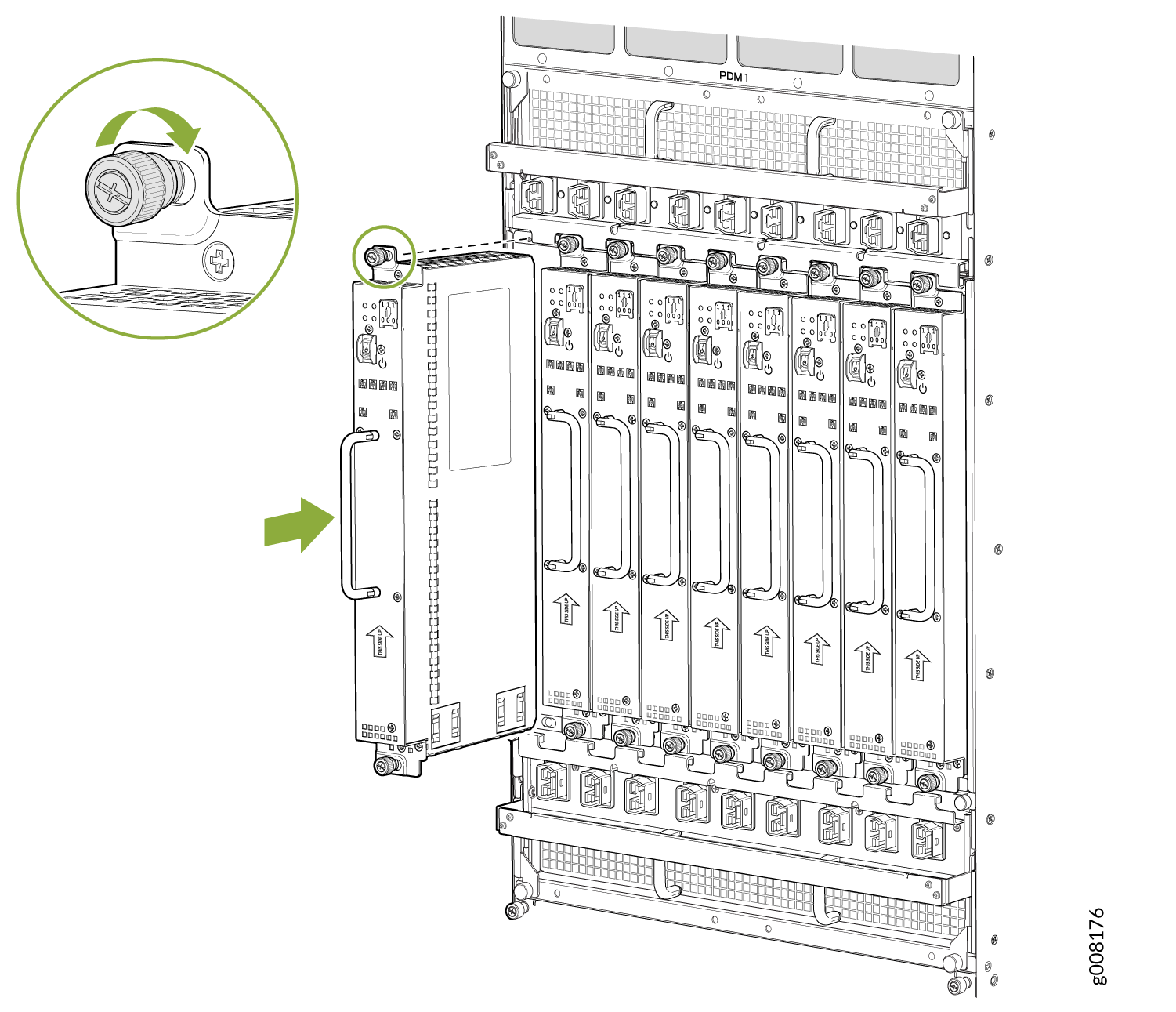
Removing an MX2008 AC Power Supply Module
Before you remove a PSM, be aware of the following:
To maintain proper cooling and prevent thermal shutdown of the operating PSM, each PSM slot must contain either a PSM or a blank panel. If you remove a PSM, you must install a replacement PSM or a blank panel shortly after the removal.
After powering off a PSM, wait at least 60 seconds before turning it back on.
To remove an AC PSM (see Figure 1):
The minimum number of AC PSMs changes based on the configuration.
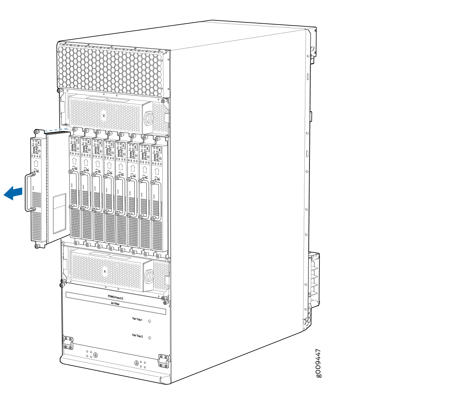
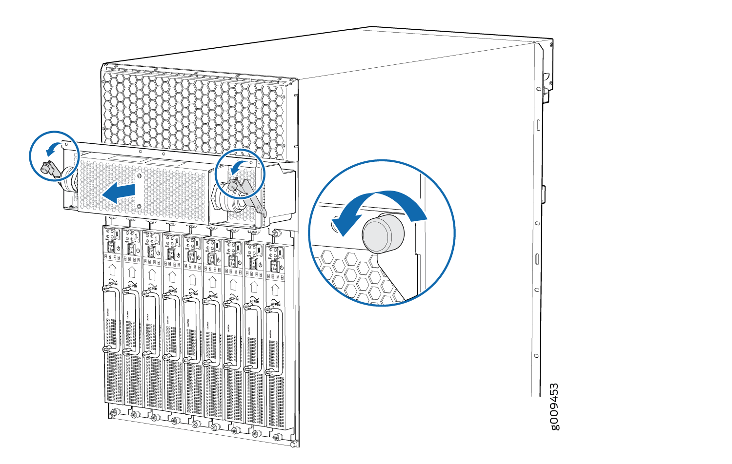
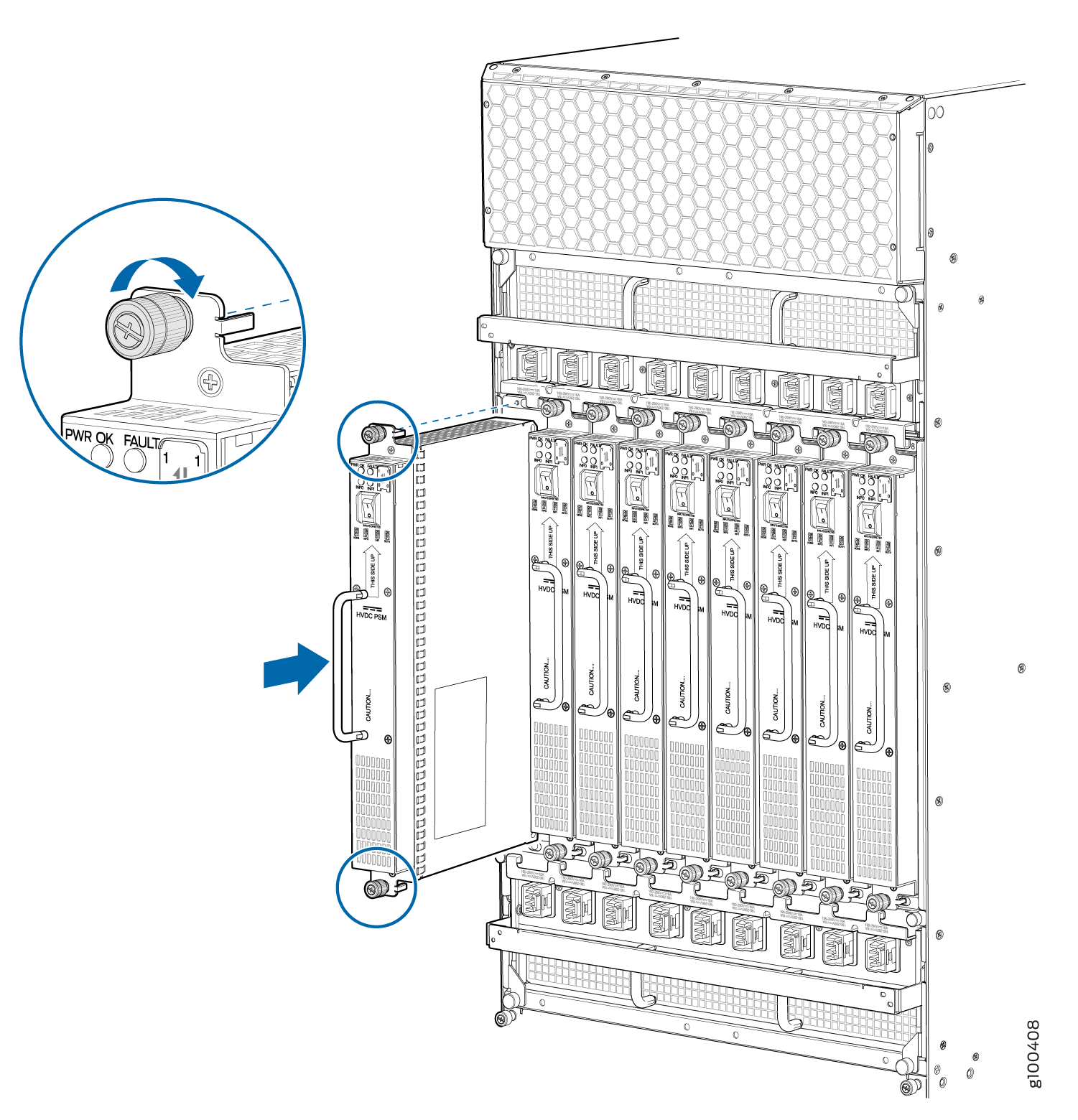
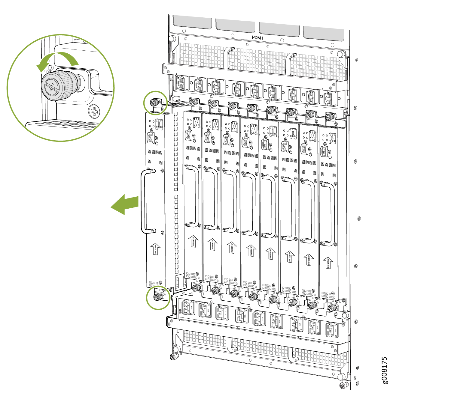
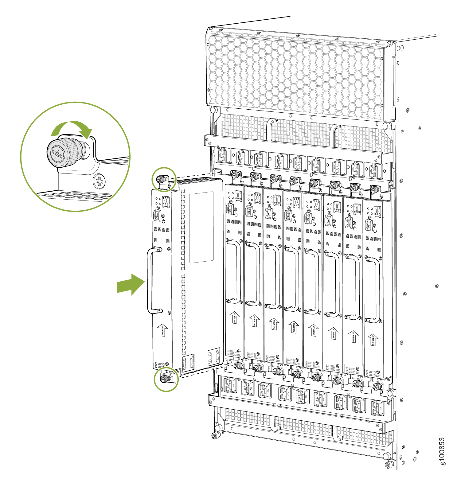
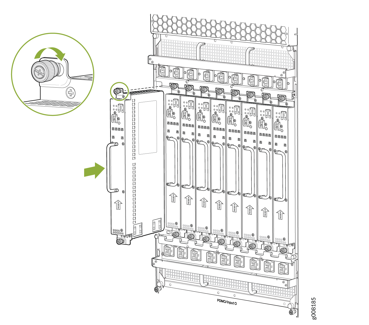
Installing an MX2008 AC Power Supply Module
Before you install a PSM, be aware of the following:
The AC PSM is hot-swappable when a minimum number of PSMs installed and operational.
The AC PSMs have no circuit breakers that can physically disconnect AC line from the router. After AC feeds have been connected to the PDM, the AC voltage is always present on the power midplane and is distributed to the PSM connectors on the power midplane.
To maintain proper cooling and prevent thermal shutdown of the operating PSM, each PSM slot must contain either a PSM or a blank panel. If you remove a PSM, you must install a replacement PSM or a blank panel shortly after the removal.
After powering on a PSM, wait at least 60 seconds before turning it back off.
To install an AC PSM (see Figure 2):
Replacing an MX2000 Three-Phase Delta AC Power Distribution Module
- Removing an MX2000 Three-Phase Delta AC Power Distribution Module
- Installing an MX2000 Router Three-Phase Delta AC Power Distribution Module
Removing an MX2000 Three-Phase Delta AC Power Distribution Module
Before you remove a three-phase delta AC PDM, be aware of the following:
Before performing AC power procedures, disconnect all power sources. To ensure that all power is OFF, locate the circuit breaker on the panel board that services the AC circuit, switch the circuit breaker to the OFF position, and tape the switch handle of the circuit breaker in the OFF position.
Do not touch the power connectors on the PDM. They can contain dangerous voltages.
To maintain proper cooling and prevent thermal shutdown of the operating power supply unit, each PDM slot must contain either a PDM or a blank panel. If you remove a PDM, you must install a replacement PDM or a blank panel shortly after the removal.
After powering off a PDM, wait at least 60 seconds before turning the circuit breaker to the ON position.
The MX2008, MX2010, and MX2020 routers support the same power modules (AC/DC PSMs and AC/DC PDMs).
To remove a three-phase delta AC PDM:
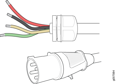
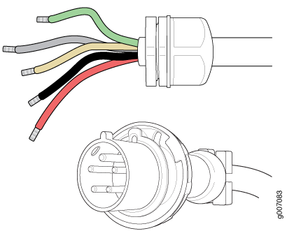
- Disconnect the AC power cord (see Figure 3) from the power source.Figure 3: Three-Phase Delta AC Power Cord
- Disconnect the wires from the AC terminal block on the
three-phase delta AC PDM (see Figure 4), loosen each
of the input terminals or grounding
point screws, and remove each wire
form the grounding point or input terminal.
To remove wires from the terminal block that serves six PSMs:
Remove the wire labeled L3 from the input terminal labeled C1.
Remove the wire labeled L2 from the input terminal labeled B1.
Remove the wire labeled L1 from the input terminal labeled A1.
Remove the grounding wire from the grounding point labeled GND.
Figure 4: Disconnecting the Power Cord from a Three-Phase Delta AC Power Distribution Module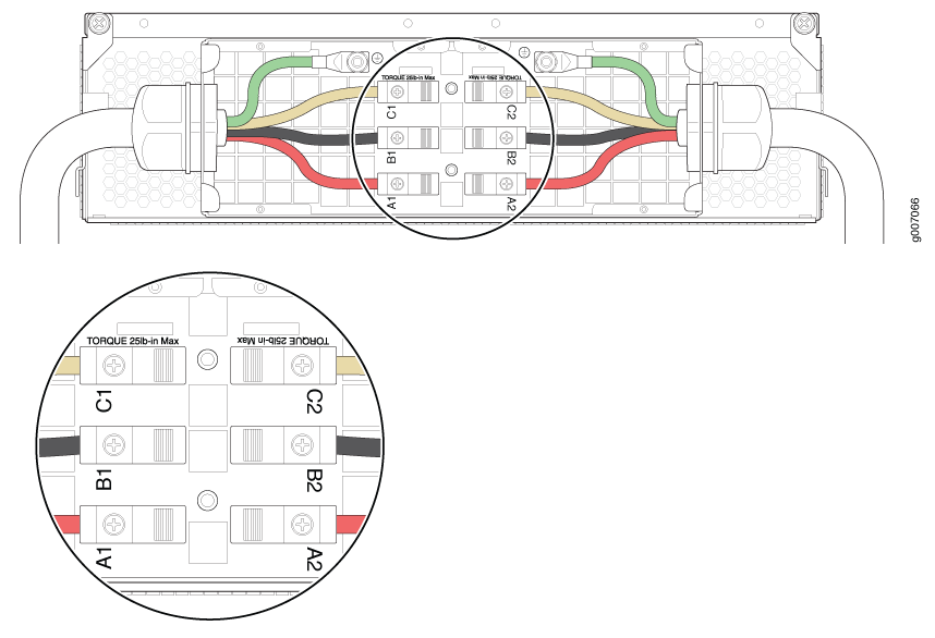
To remove wires from the terminal block that serves three PSMs:
Remove the wire labeled L3 from the input terminal labeled C2.
Remove the wire labeled L2 from the input terminal labeled B2.
Remove the wire labeled L1 from the input terminal labeled A2.
Remove the grounding wire from the grounding point labeled GND.
Note:The three-phase delta AC PDM terminal blocks will be flipped depending on which slot the PDM gets plugged into.
Note:The color of each AC power wire might vary. The MX2000 chassis is not sensitive to phase rotation sequence—either clockwise or counterclockwise will operate correctly.
Note:The terminal connections have either slotted screws or hex screws. Use a 1/4-in. slotted screwdriver for the slotted screws. Use a 5/32-in. (4 mm) Allen wrench for the 5/16-in. hex screws.

Each PDM slot not occupied by a AC PDM must be covered by a PDM blank panel.
See Also
Installing an MX2000 Router Three-Phase Delta AC Power Distribution Module
Before you install a three-phase delta AC power distribution module (PDM), be aware of the following:
Before performing AC power procedures, disconnect all power sources. To ensure that all power is off, locate the circuit breaker on the panel board that services the AC circuit, switch the circuit breaker to the off position, and tape the switch handle of the circuit breaker in the off position.
To maintain proper cooling and prevent thermal shutdown of the operating power supply unit, each PDM slot must contain either a PDM or a blank panel. If you remove a PDM, you must install a replacement PDM or a blank panel shortly after the removal.
After powering off a PDM, wait at least 60 seconds before turning the circuit breaker back on.
The PDMs are hot swappable in a redundant configuration. However, you cannot switch from one type of PDM (AC or DC) to another while the system is on.
Each three-phase delta AC PDM weighs approximately 12 lb (5.44 kg). To install a three-phase delta AC PDM:
- Using a number 2 Phillips (+) screwdriver, loosen the
four screws on the cover of the metal wiring compartment that protects
the AC terminal block.Figure 8: Installing a Three-Phase Delta AC Power Distribution Module (MX2020)
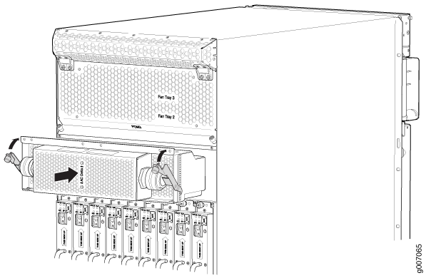 Figure 9: Installing a Three-Phase Delta AC Power Distribution Module (MX2010)
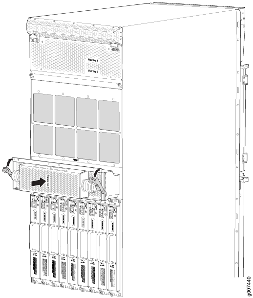 Figure 10: Installing a Three-Phase Delta AC Power Distribution Module (MX2008)
- Connect the wires to the AC terminal block on the three-phase
delta AC PDM (see Figure 11). Loosen each of the input terminals or grounding point screws,
and insert the wire into the grounding point or input terminal, and
tighten the screw (see Table 1 for approved AC wire gauge).
To insert wires into the terminal block that serves six PSMs:
Insert the grounding wire into the grounding point labeled GND.
Insert the wire labeled L1 into the input terminal labeled A1.
Insert the wire labeled L2 into the input terminal labeled B1.
Insert the wire labeled L3 into the input terminal labeled C1.
Figure 11: Connecting Power to a Three-Phase Delta AC Power Distribution ModuleNote:The three-phase delta AC PDM terminal blocks will be flipped depending on which slot the PDM gets plugged into.
Note:The color of each AC power wire might vary. The MX2000 chassis is not sensitive to phase rotation sequence—either clockwise or counterclockwise will operate correctly.
CAUTION:Wire label configuration is for Juniper Networks supplied cable only. If you are using your own cable, make sure you use the proper connections.
To insert wires into the terminal block that serves three PSMs:
Insert the grounding wire into the grounding point labeled GND.
Insert the wire labeled L1 into the input terminal labeled A2.
Insert the wire labeled L2 into the input terminal labeled B2.
Insert the wire labeled L3 into the input terminal labeled C2.
Note:The terminal connections have either slotted screws or hex screws. Use a 1/4-in. slotted screwdriver for the slotted screws. Use a 5/32-in. (4 mm) Allen wrench for the 5/16-in. hex screws.
Warning:To protect power supplies from input voltage that might be caused by mis-wired PDMs, before reinstalling the metal cover to the wiring compartment, apply AC voltage to the PDM (with the PSM power switch turned off). Verify that the two LEDs on the PDM are lit green and that the AC voltage between AC terminal blocks A1-B1, B1-C1, C1-A1, A2-B2, B2-C2, and C2-A2 for three-phase delta PDM is not more than 264 VAC when measured with a digital voltage meter (DVM). Then turn off the AC breaker to remove power from the PDM and install the metal cover.
Note:Three-phase delta AC wire assembly kits can be purchased from Juniper Networks.
Table 1: Supported Three-Phase Delta AC Wire Gauge Wire Gauge Description 4 x 6-AWG or equivalent
4 conductor wires, each wire is 6-AWG
Note:We recommend that you use the proper gauge wire in order for the cable clamps to hold the AC cables. Using smaller gauge wiring will result in the cable clamps not tightening properly.
Warning:Power connections must be performed by a licensed electrician only.
Replacing an MX2008 Three-Phase Delta AC Power Cord
The MX2008 router has either one redundant PDM or two redundant PDMs. An AC power cord on a redundant PDM is hot-insertable and hot-removable. When a redundant PDM is powered down, the other PDM automatically assumes the entire electrical load for the router. If you have only one PDM, you must power off the system before removing the AC power cord.
- Removing an MX2008 Three-Phase Delta AC Power Cord
- Installing an MX2008 Three-Phase Delta AC Power Cord
Removing an MX2008 Three-Phase Delta AC Power Cord
To remove a three-phase delta AC power cord:
- Disconnect the AC power cord (see Figure 12) from the power source.Figure 12: Three-Phase Delta AC Power Cord
- Disconnect the wires from the AC terminal block on the
three-phase delta AC PDM (see Figure 13). Loosen each of
the input terminals or grounding point screws, and remove each wire
from the grounding point or input terminal.Note:
The terminal connections have either slotted screws or hex screws. Use a 1/4-in. slotted screwdriver for the slotted screws. Use a 5/32-in. (4 mm) Allen wrench for the 5/16-in. hex screws.
To remove wires from the terminal block that serves six PSMs:
Remove the wire labeled L3 from the input terminal labeled C1.
Remove the wire labeled L2 from the input terminal labeled B1.
Remove the wire labeled L1 from the input terminal labeled A1.
Remove the grounding wire from the grounding point labeled GND.
Figure 13: Disconnecting the Power Cord from a Three-Phase Delta AC Power Distribution ModuleTo remove wires from the terminal block that serves three PSMs:
Remove the wire labeled L3 from the input terminal labeled C2.
Remove the wire labeled L2 from the input terminal labeled B2.
Remove the wire labeled L1 from the input terminal labeled A2.
Remove the grounding wire from the grounding point labeled GND.
Note:The three-phase delta AC PDM terminal blocks will be flipped depending on which slot the PDM gets plugged into.
Installing an MX2008 Three-Phase Delta AC Power Cord
To install a three-phase delta AC power cord:
- Connect the wires to the AC terminal block on the three-phase
delta AC PDM (see Figure 14).
Loosen each of the input terminal or grounding point screws, and insert
the wire into the grounding point or input terminal, and tighten the
screw (see Table 2 for approved
AC wire gauge).
To insert wires into the terminal block that serves six PSMs:
Insert the grounding wire into the grounding point labeled GND.
Insert the wire labeled L1 into the input terminal labeled A1.
Insert the wire labeled L2 into the input terminal labeled B1.
Insert the wire labeled L3 into the input terminal labeled C1.
Figure 14: Connecting Power to a Three-Phase Delta AC Power Distribution ModuleNote:The three-phase delta AC PDM terminal blocks will be flipped depending on which slot the PDM gets plugged into.
Note:The color of each AC power wire might vary. The MX2008 chassis is not sensitive to phase rotation sequence—either CW or CCW will operate correctly.
CAUTION:Wire label configuration is for Juniper Networks supplied cable only. If you are using your own cable, make sure you use the proper connections.
To insert wires into the terminal block that serves three PSMs:
Insert the grounding wire into the grounding point labeled GND.
Insert the wire labeled L1 into the input terminal labeled A2.
Insert the wire labeled L2 into the input terminal labeled B2.
Insert the wire labeled L3 into the input terminal labeled C2.
Note:The terminal connections have either slotted screws or hex screws. Use a 1/4-in. slotted screwdriver for the slotted screws. Use a 5/32-in. (4 mm) Allen wrench for the 5/16-in. hex screws.
Warning:To protect power supplies from input voltage that might be caused by mis-wired PDMs, before reinstalling the metal cover to the wiring compartment, apply AC voltage to the PDM (with disengaged PSM) to make sure that two LEDs on the PDM are lit green and that the AC voltage between AC terminal blocks A1-B1, B1-C1, C1-A1, A2-B2, B2-C2, and C2-A2 for three-phase delta PDM is not more than 264 VAC when measured with a digital voltage meter (DVM). Then turn off the AC breaker, de-energizing the PDM, and install the metal cover and engage all AC PSMs.
Note:Three-phase delta AC wire assembly kits can be purchased from Juniper Networks.
Table 2: Supported Three-Phase Delta AC Wire Gauge Wire Gauge Description 4 x 6-AWG or equivalent
4 conductor wires, each wire is 6-AWG
Note:We recommend that you use the proper gauge wire in order for the cable clamps to hold the AC cables. Using smaller gauge wiring will result in the cable clamps not tightening properly.
Warning:Power connections must be performed by a licensed electrician only.
Replacing an MX2020 Three-Phase Wye AC Power Distribution Module
- Removing an MX2000 Three-Phase Wye AC Power Distribution Module
- Installing an MX2000 Router Three-Phase Wye AC Power Distribution Module
Removing an MX2000 Three-Phase Wye AC Power Distribution Module
Before you remove a three-phase wye AC Power Distribution Module (PDM), be aware of the following:
Before performing AC power procedures, disconnect all power sources. To ensure that all power is off, locate the circuit breaker on the panel board that services the AC circuit, move the circuit breaker to the OFF position, and tape the switch handle of the circuit breaker in the OFF position.
Do not touch the power connectors on the PDM. They can contain dangerous voltages.
To maintain proper cooling and prevent thermal shutdown of the operating power supply unit, each PDM slot must contain either a PDM or a blank panel. If you remove a PDM, you must install a replacement PDM or a blank panel shortly after the removal.
After powering off a PDM, wait at least 60 seconds before turning the circuit breaker back on.
To remove a three-phase wye AC PDM:
- Disconnect the AC power cord (see Figure 15) from the power source.Figure 15: Three-Phase Wye AC Power Cord
- Disconnect the wires from the AC terminal block on the
three-phase wye AC PDM (see Figure 16), loosen each
of the input terminals or grounding point screws, and remove each
wire from the grounding point or input terminal.
To remove wires from the terminal block that serves six PSMs:
Remove the wire labeled N from the input terminal labeled N1.
Remove the wire labeled L3 from the input terminal labeled C1.
Remove the wire labeled L2 from the input terminal labeled B1.
Remove the wire labeled L1 from the input terminal labeled A1.
Remove the grounding wire from the grounding point labeled GND.
Figure 16: Disconnecting the Power Cord from a Three-Phase Wye AC Power Distribution Module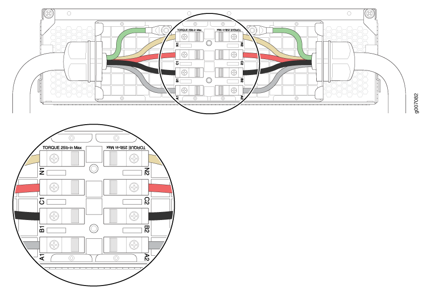
To remove wires from the terminal block that serves three PSMs:
Remove the wire labeled N from the input terminal labeled N2.
Remove the wire labeled L3 from the input terminal labeled C2.
Remove the wire labeled L2 from the input terminal labeled B2.
Remove the wire labeled L1 from the input terminal labeled A2.
Remove the grounding wire from the grounding point labeled GND.
Note:The three-phase wye AC PDM terminal blocks will be flipped depending on which slot the PDM gets plugged in to.
Note:The terminal connections have either slotted screws or hex screws. Use a 1/4-in. slotted screwdriver for the slotted screws. Use a 5/32-in. (4 mm) Allen wrench for the 5/16-in. hex screws.
Each PDM slot not occupied by a AC PDM must be covered by a PDM blank panel.
Installing an MX2000 Router Three-Phase Wye AC Power Distribution Module
Each three-phase wye AC PDM weighs approximately 12 lb (5.44 kg). To install a three-phase wye AC PDM:
Before performing AC power procedures, ensure that power is removed from the AC circuit. To ensure that all power is off, locate the circuit breaker on the panel board that services the AC circuit, switch the circuit breaker to the off position, and tape the switch handle of the circuit breaker in the off position.
To maintain proper cooling and prevent thermal shutdown of the operating power supply unit, each PDM slot must contain either a PDM or a blank panel. If you remove a PDM, you must install a replacement PDM or a blank panel shortly after the removal.
After powering off a PDM, wait at least 60 seconds before turning the circuit breaker back on.
The PDMs are hot swappable in a redundant configuration. However, you cannot convert to a DC configuration while the system is on.
- Using both hands, slide the PDM into the chassis until
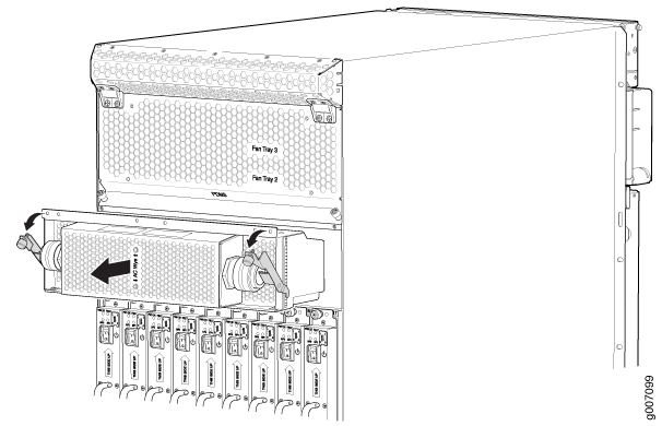
you feel resistance (see Figure 20, Figure 21, or Figure 22.Figure 20: Installing a Three-Phase Wye AC PDM (MX2020)Figure 21: Installing a Three-Phase Wye AC PDM (MX2010)Figure 22: Installing an Three-Phase Wye AC PDM (MX2008)
- Connect the wires to the AC terminal block on the three-phase
wye AC PDM (see Figure 23). Loosen each of the input terminals or grounding point screws,
insert the wire into the grounding point or input terminal, and tighten
the screw (see Table 3 for approved
AC wire gauge).
To insert wires into the terminal block that serves six PSMs:
Insert the grounding wire into the grounding point labeled GND.
Insert the wire labeled L1 into the input terminal labeled A1.
Insert the wire labeled L2 into the input terminal labeled B1.
Insert the wire labeled L3 into the input terminal labeled C1.
Insert the wire labeled N into the input terminal labeled N1.
Figure 23: Connecting Power to a Three-Phase Wye AC Power Distribution ModuleNote:The three-phase wye AC PDM terminal blocks will be flipped depending on which slot the PDM gets plugged into.
Note:The color of each AC power wire might vary. The MX2000 chassis is not sensitive to phase rotation sequence—either CW or CCW will operate correctly.
CAUTION:Wire label configuration is for Juniper Networks supplied cable only. If using your own cable, make sure you use the proper connections.
To insert wires into the terminal block that serves three PSMs:
Insert the grounding wire into the grounding point labeled GND.
Insert the wire labeled L1 into the input terminal labeled A2.
Insert the wire labeled L2 into the input terminal labeled B2.
Insert the wire labeled L3 into the input terminal labeled C2.
Insert the wire labeled N into the input terminal labeled N2.
Warning:To protect power supplies from input voltage that might be caused by mis-wired PDMs, before reinstalling the metal cover to the wiring compartment, apply AC voltage to the PDM (with disengaged PSM) to make sure that two LEDs on the PDM are lit green and that the AC voltage between AC terminal blocks A1-N1, B1-N1, C1-N1, A2-N2, B2-N2, and C2-N2 for three-phase wye PDM is not more than 264 VAC when measured with a digital voltage meter (DVM). Then turn off the AC breaker de-energizing the PDM and install the metal cover and engage all AC PSMs.
Note:The terminal connections have either slotted screws or hex screws. Use a 1/4-in. slotted screwdriver for the slotted screws. Use a 5/32-in. (4 mm) Allen wrench for the 5/16-in. hex screws.
Note:Three-phase wye AC wire assembly kits can be purchased from Juniper Networks.
Table 3: Supported Three-Phase Wye AC Wire Gauge Wire Gauge Description 5 x 10-AWG or equivalent
5 conductor wires, each wire is 10-AWG
Note:We recommend that you use the proper gauge wire in order for the cable clamps to hold the AC cables. Using smaller gauge wiring will result in the cable clamps not tightening properly.
Warning:Power connections must be performed by a licensed electrician only.
Replacing an MX2008 Three-Phase Wye AC Power Cord
The MX2008 router has either one redundant PDM or two redundant PDMs. An AC power supply cord on a redundant PDM is hot-insertable and hot-removable. When a redundant PDM is powered down, the other PDM automatically assumes the entire electrical load for the router. If you have only one PDM, you must power off the system before removing the AC power supply cord.
Removing an MX2008 Three-Phase Wye AC Power Cord
To remove a three-phase wye AC power cord:
- Disconnect the AC power cord (see Figure 24) from the
power source.Figure 24: Three-Phase Wye AC Power Supply Cord
- Disconnect the wires from the AC terminal block on the
three-phase wye AC PDM (see Figure 25). Loosen each of
the input terminals or grounding point screws, and remove each wire
from the grounding point or input terminal.Note:
The terminal connections have either slotted screws or hex screws. Use a 1/4-in. slotted screwdriver for the slotted screws. Use a 5/32-in. (4 mm) Allen wrench for the 5/16-in. hex screws.
To remove wires from the terminal block that serves six PSMs:
Remove the wire labeled N from the input terminal labeled N1.
Remove the wire labeled L3 from the input terminal labeled C1.
Remove the wire labeled L2 from the input terminal labeled B1.
Remove the wire labeled L1 from the input terminal labeled A1.
Remove the grounding wire from the grounding point labeled GND.
Figure 25: Disconnecting the Power Cord from a Three-Phase Wye AC Power Distribution ModuleTo remove wires from the terminal block that serves three PSMs:
Remove the wire labeled N from the input terminal labeled N2.
Remove the wire labeled L3 from the input terminal labeled C2.
Remove the wire labeled L2 from the input terminal labeled B2.
Remove the wire labeled L1 from the input terminal labeled A2.
Remove the grounding wire from the grounding point labeled GND.
Note:The three-phase wye AC PDM terminal blocks will be flipped depending on which slot the PDM gets plugged into.
Installing an MX2008 Three-Phase Wye AC Power Cord
To install a three-phase wye AC power cord:
- Connect the wires to the AC terminal block on the three-phase
delta AC PDM (see Figure 26).
Loosen each of the input terminal or grounding point screws, insert
the wire into the grounding point or input terminal, and tighten the
screw (see Table 4 for approved
AC wire gauge).
To insert wires into the terminal block that serves six PSMs:
Insert the grounding wire into the grounding point labeled GND.
Insert the wire labeled L1 into the input terminal labeled A1.
Insert the wire labeled L2 into the input terminal labeled B1.
Insert the wire labeled L3 into the input terminal labeled C1.
Insert the wire labeled N into the input terminal labeled N1.
Figure 26: Connecting Power to a Three-Phase Wye AC Power Distribution ModuleNote:The three-phase wye AC PDM terminal blocks will be flipped depending on which slot the PDM gets plugged into.
Note:The color of each AC power wire might vary. The MX2008 chassis is not sensitive to phase rotation sequence—either CW or CCW will operate correctly.
CAUTION:Wire label configuration is for Juniper Networks supplied cable only. If using your own cable, make sure you use the proper connections.
To insert wires into the terminal block that serves three PSMs:
Insert the grounding wire into the grounding point labeled GND.
Insert the wire labeled L1 into the input terminal labeled A2.
Insert the wire labeled L2 into the input terminal labeled B2.
Insert the wire labeled L3 into the input terminal labeled C2.
Insert the wire labeled N into the input terminal labeled N2.
Note:The terminal connections have either slotted screws or hex screws. Use a 1/4-in. slotted screwdriver for the slotted screws. Use a 5/32-in. (4 mm) Allen wrench for the 5/16-in. hex screws.
Warning:To protect power supplies from input voltage that might be caused by mis-wired PDMs, before reinstalling the metal cover to the wiring compartment, apply AC voltage to the PDM (with disengaged PSM) to make sure that two LEDs on the PDM are lit green and that the AC voltage between AC terminal blocks A1-N1, B1-N1, C1-N1, A2-N2, B2-N2, and C2-N2 for three-phase wye PDM is not more than 264 VAC when measured with a digital voltage meter (DVM). Then turn off the AC breaker, de-energizing the PDM, and install the metal cover and engage all AC PSMs.
Note:Three-phase wye AC wire assembly kits can be purchased from Juniper Networks.
Table 4: Supported Three-Phase Wye AC Wire Gauge Wire Gauge Description 5 x 10-AWG or equivalent
5 conductor wires, each wire is 10-AWG
Note:We recommend that you use the proper gauge wire in order for the cable clamps to hold the AC cables. Using smaller gauge wiring will result in the cable clamps not tightening properly.
Warning:Power connections must be performed by a licensed electrician only.
Replacing an MX2008 DC Power Supply Module (-48 V)
- Removing an MX2008 DC Power Supply Module (-48 V)
- Installing an MX2008 DC Power Supply Module (-48 V)
Removing an MX2008 DC Power Supply Module (-48 V)
Before you remove a PSM, be aware of the following:
To maintain proper cooling and prevent thermal shutdown of the operating PSM, each PSM slot must contain either a PSM or a blank panel. If you remove a PSM, you must install a replacement PSM or a blank panel shortly after the removal.
After powering off a PSM, wait at least 60 seconds before turning it back on.
To remove a DC PSM (see Figure 27):
The DC PSM is hot-swappable, with a minimum number of PSMs installed.
Installing an MX2008 DC Power Supply Module (-48 V)
Before you install a PSM, be aware of the following:
The DC PSM is hot-swappable when a minimum number of PSMs installed and operational.
The DC PSMs have no circuit breakers that can physically disconnect DC line from the router. After DC feeds have been connected to the PDM, the DC voltage is always present on the power midplane and is distributed to the PSM connectors on the power midplane.
To maintain proper cooling and prevent thermal shutdown of the operating PSM, each PSM slot must contain either a PSM or a blank panel. If you remove a PSM, you must install a replacement PSM or a blank panel shortly after the removal.
After powering on a PSM, wait at least 60 seconds before turning it back off.
To install a DC PSM (see Figure 28):
Replacing an MX2008 DC Power Distribution Module Cable (-48 V)
- Disconnecting an MX2008 DC Power Distribution Module Cable
- Connecting an MX2008 DC Power Distribution Module Cable (-48 V)
Disconnecting an MX2008 DC Power Distribution Module Cable
Before performing DC power procedures, disconnect all power sources. To ensure that all power is off, locate the circuit breaker on the panel board that services the DC circuit, switch the circuit breaker to the OFF position, and tape the switch handle of the circuit breaker in the OFF position.
To disconnect a power cable for a DC PDM:
- Switch off the dedicated customer-site circuit breaker for the PDM being removed. Follow your site's procedures for ESD.
- Make sure that the voltage across the DC power source cable leads is 0 V and that there is no chance that the cables might become active during the removal process.
- Verify that the –48V LED on the PDM is not lit.
- Remove the power cable from the external DC power source.
- Attach an electrostatic discharge (ESD) grounding strap to your bare wrist, and connect the strap to one of the ESD points on the chassis.
- Remove the clear plastic cover protecting the terminal studs on the faceplate.
- Remove the nut and washers from each of the terminal studs. (Use a 7/16-in. [11 mm] nut driver or socket wrench.)
- Remove the cable lug from the terminal studs.
- Carefully move the power cable out of the way.
- Replace the clear plastic cover protecting the terminal studs on the faceplate.
Connecting an MX2008 DC Power Distribution Module Cable (-48 V)
Before performing DC power procedures, disconnect all power sources. To ensure that all power is off, locate the circuit breaker on the panel board that services the DC circuit, switch the circuit breaker to the OFF position, and tape the switch handle of the circuit breaker in the OFF position.
To connect a power cable for a DC PDM:
- Secure the power cable lug to the terminal studs, first
with the flat washer, then with the split washer, and finally with
the nut. Apply between 23 lb-in. (2.6 Nm) and 25 lb-in.
(2.8 Nm) of torque to each nut (see Figure 29). Do not overtighten
the nut. (Use a 7/16-in. [11 mm)] torque-controlled driver
or socket wrench.)CAUTION:
Ensure that each power cable lug seats flush against the surface of the terminal block as you are tightening the nuts. Ensure that each nut is properly threaded onto the terminal stud. The nut should be able to spin freely with your fingers when it is first placed onto the terminal stud. Applying installation torque to the nut when the nut is improperly threaded might result in damage to the terminal stud.
CAUTION:The maximum torque rating of the terminal studs on the DC PDM is 25 lb-in. (33.89 Nm). The terminal studs might be damaged if excessive torque is applied. Use only a torque-controlled driver or socket wrench to tighten nuts on the DC PDM terminal studs.
Figure 29: Connecting Power Cables to the DC Power Distribution Module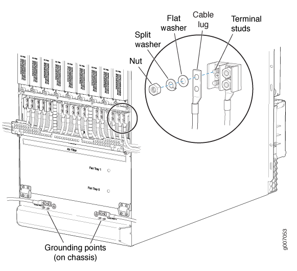
Replacing an MX2000 DC Power Supply Module (240 V China)
- Removing an MX2000 Router DC Power Supply Module (240 V China)
- Installing an MX2000 Router DC Power Supply Module (240 V China)
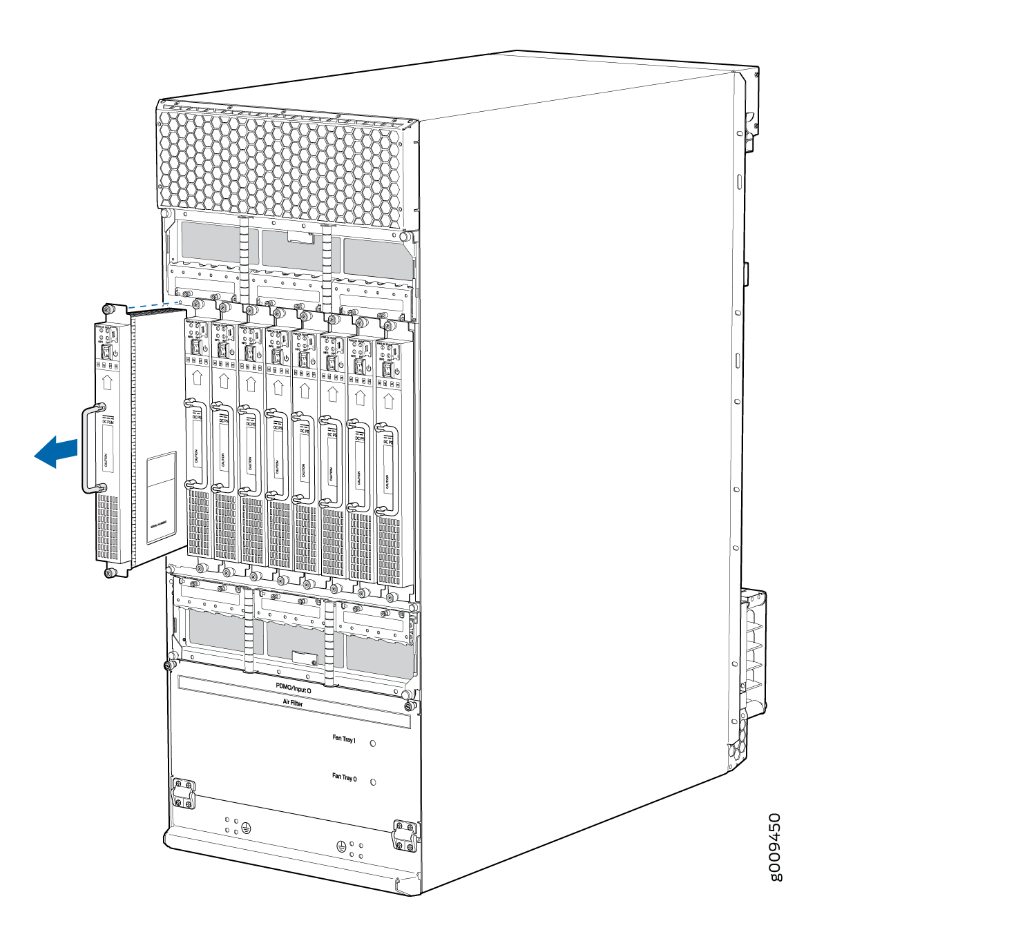
Removing an MX2000 Router DC Power Supply Module (240 V China)
Before you remove a PSM, be aware of the following:
To maintain proper cooling and prevent thermal shutdown of the operating PSM, each PSM slot must contain either a PSM or a blank panel. If you remove a PSM, you must install a replacement PSM or a blank panel shortly after the removal.
After powering off a PSM, wait at least 60 seconds before turning it back on.
To remove a DC PSM (see Figure 30 and Figure 30):
The minimum number of DC PSMs change, based on the configuration.
See Also
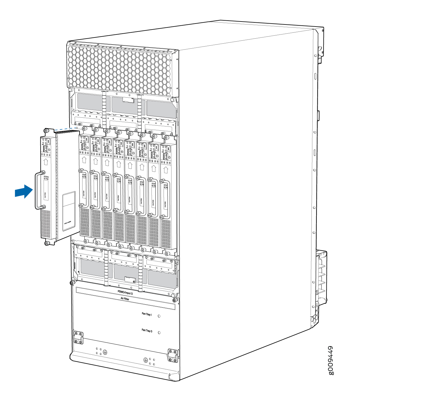
Installing an MX2000 Router DC Power Supply Module (240 V China)
Before you install a DC PSM (240 V China), be aware of the following:
The DC PSM is hot-swappable when a minimum number of PSMs installed and operational.
The DC PSMs have no circuit breakers that can physically disconnect DC current from the router. After DC feeds have been connected to the PDM, the DC voltage is always present on the power midplane and is distributed to the PSM connectors on the power midplane.
To maintain proper cooling and prevent thermal shutdown of the operating PSM, each PSM slot must contain either a PSM or a blank panel. If you remove a PSM, you must install a replacement PSM or a blank panel shortly after the removal.
After powering on a PSM, wait at least 60 seconds before turning it back off.
To install a DC PSM (see Figure 31):
Replacing an MX2000 DC Power Distribution Module (240 V China)
- Removing an MX2000 Router DC Power Distribution Module (240 V China)
- Installing an MX2000 Router DC Power Distribution Module (240 V China)
- Connecting an MX2000 DC Router Power Distribution Module (240 V China) Cable
Removing an MX2000 Router DC Power Distribution Module (240 V China)
Before you remove a PDM, be aware of the following:
The minimum number of PDMs must be present in the router at all times.
Before performing DC power procedures, disconnect all power sources. To ensure that all power is off, locate the circuit breaker on the panel board that services the DC circuit, switch the circuit breaker to the OFF position, and tape the switch handle of the circuit breaker in the OFF position.
To maintain proper cooling and prevent thermal shutdown of the operating power supply unit, each PDM slot must contain either a PDM or a blank panel. If you remove a PDM, you must install a replacement PDM or a blank panel shortly after the removal.
After powering off a PDM, wait at least 60 seconds before turning the circuit breaker back on.
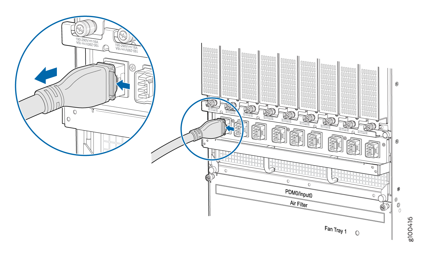
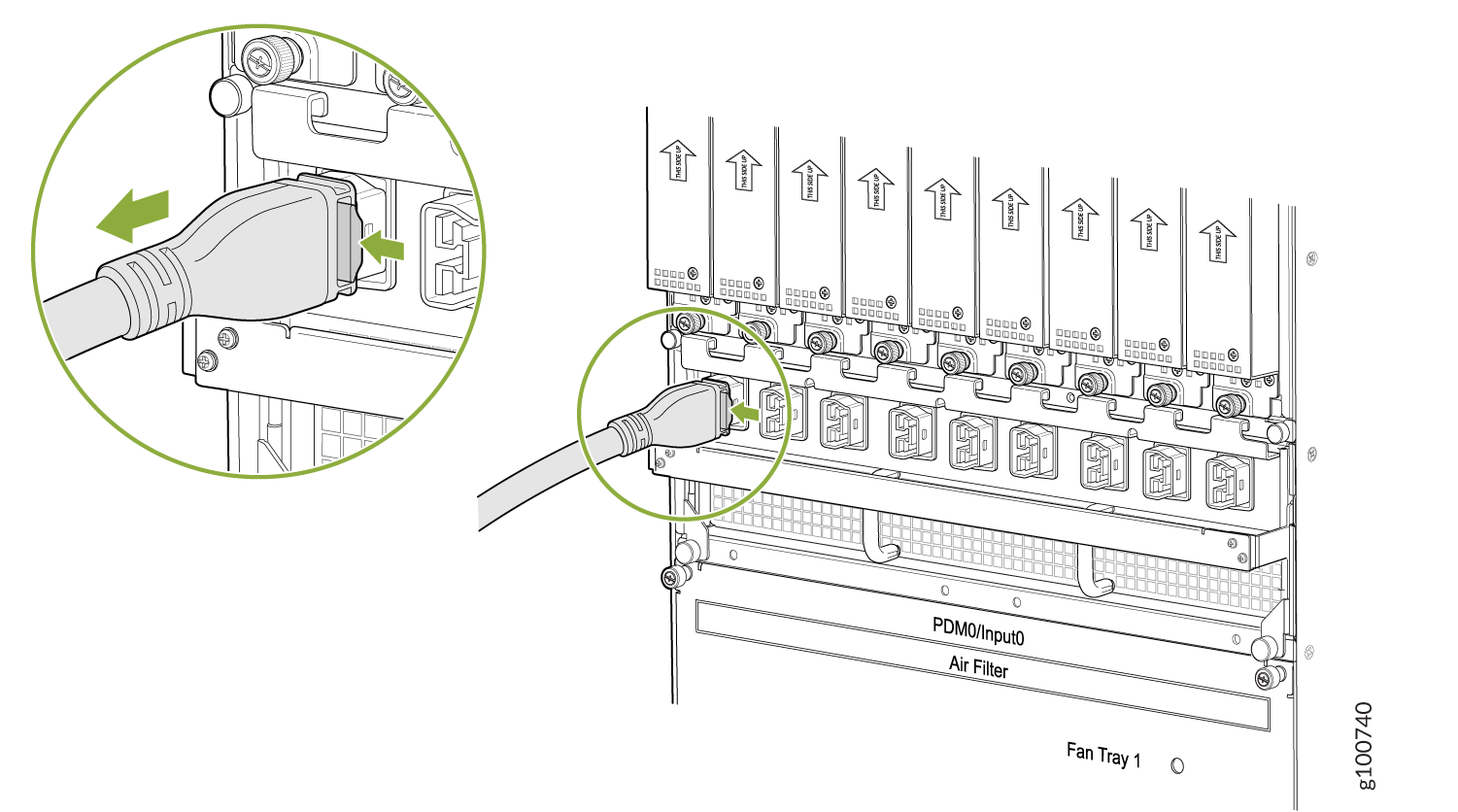
- Starting at one end of the PDM, unplug all the power cords.
Press the latch on the side of the power cable before pulling it out.
See Figure 32.Figure 32: Unplugging the 240 V China Power Cord an MX2000 Router
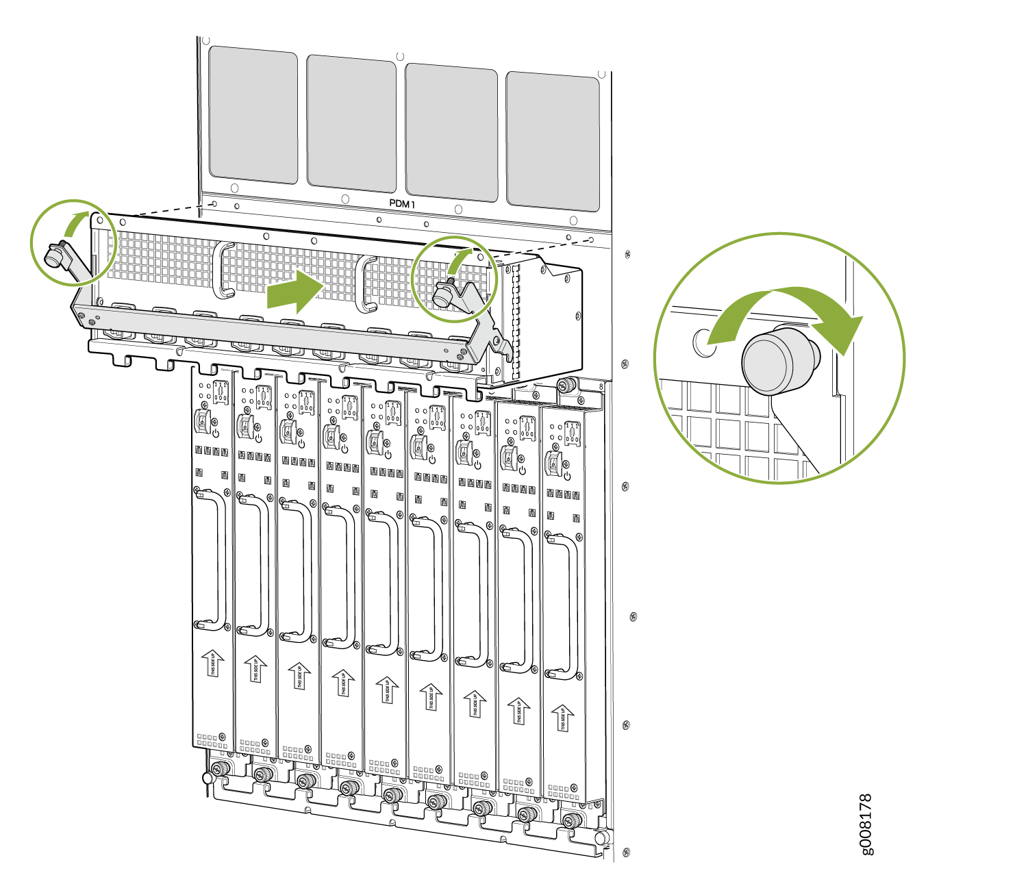
- Loosen the two captive screws on the locking levers, and
pull away from the chassis. See Figure 33.Note:
For the MX2020 Router, pull down the PDM3/Input1 and PDM1/Input1 locking levers to release the PDM from the chassis, and pull up the PDM0/Input0 and PDM2/Input0 locking levers to release the PDM from the chassis.
Note:For the MX2010 and MX2008 Routers, pull down the PDM1/Input1 locking levers to release the PDM from the chassis, and pull up the PDM0/Input0 locking levers to release the PDM from the chassis.
Figure 33: Removing a DC PDM (240 V China) from an MX2000 Router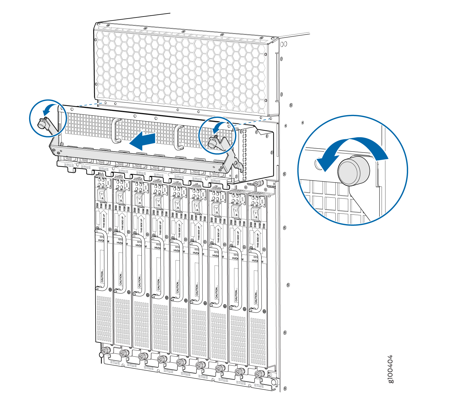
Installing an MX2000 Router DC Power Distribution Module (240 V China)
Before performing DC power procedures, disconnect all power sources. To ensure that all power is off, locate the circuit breaker on the panel board that services the DC circuit, switch the circuit breaker to the off position, and tape the switch handle of the circuit breaker in the off position.
To install a DC power distribution module (PDM) in an MX2000 Router:
- While holding both handles, guide the PDM until the locking
levers are inserted into the chassis. With both hands push the locking
levers simultaneously until the PDM is fully seated into the chassis
(see Figure 34).Figure 34: Installing an MX2020 Router DC Power Distribution Module (240 V China)
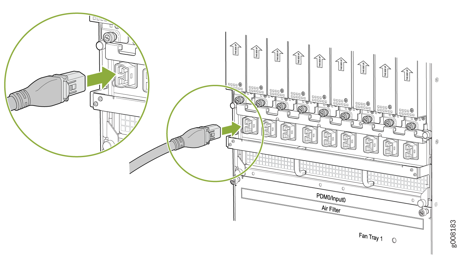
- Starting at one end of the PDM, plug the power cords into
the power sockets on the PDM. Press the latch on the side of the power
cable before pushing it in. Apply slight pressure so that the power
cord is firmly seated in the power socket until you feel it engage.
As you plug in each power cord, the power LED for the socket lights
up green. See Figure 35.Figure 35: Plugging the 240 V China Power Cord an MX2000 Router
Connecting an MX2000 DC Router Power Distribution Module (240 V China) Cable
Before performing DC power procedures, disconnect all power sources. To ensure that all power is OFF, locate the circuit breaker on the panel board that services the DC circuit, switch the circuit breaker to the OFF position, and tape the switch handle of the circuit breaker in the OFF position.
To connect the DC (240 V China) source power cables (CBL-PWR-240V-CH) to the router:
- Plug the power cord into the power sockets
on the DC PDM (240 V China). Refer to Figure 1. Press the latch on
the side of the power cable before pushing it in. Apply slight pressure
so that the power cord is firmly seated in the power socket until
you feel it engage. As you plug in each power cord, the power LED
for the socket lights up green.Figure 36: Connecting Power
- Connect the power cable (CBL-PWR-240V-CH) to the DC power
source. See Figure 37.Figure 37: 240 V China Power Cable
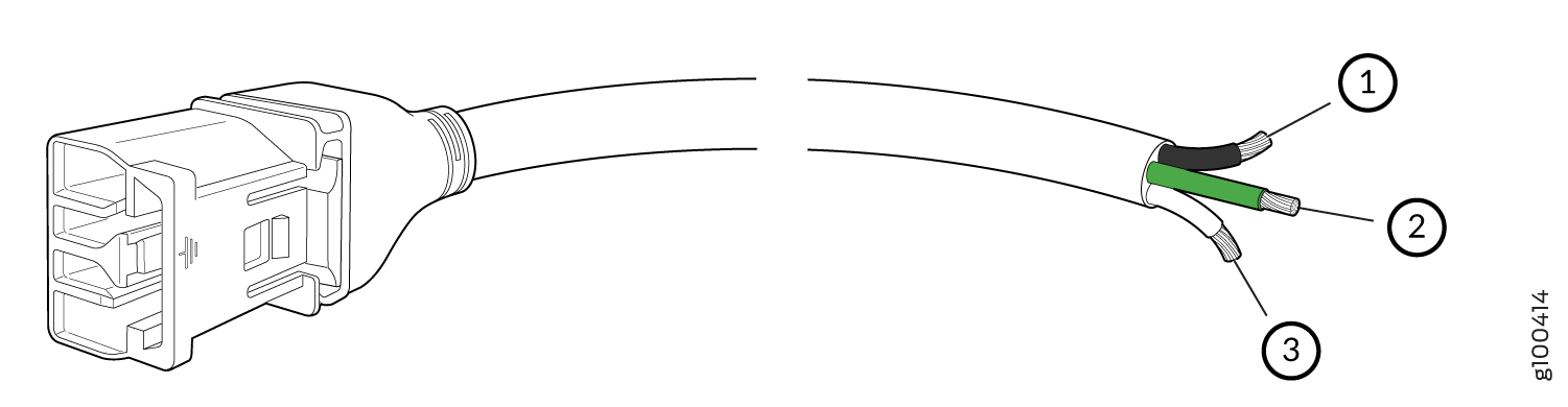 1—
1—Negative
3—Positive
2—Ground
Replacing an MX2000 High-Voltage Second-Generation Universal (HVAC/HVDC) Power Supply Module
- Removing an MX2000 Router High-Voltage Second-Generation Universal (HVAC/HVDC) Power Supply Module
- Installing an MX2000 Router High-Voltage Universal (HVAC/HVDC) Power Supply Module
Removing an MX2000 Router High-Voltage Second-Generation Universal (HVAC/HVDC) Power Supply Module
Before you remove a PSM, be aware of the following:
To maintain proper cooling and prevent thermal shutdown of the operating PSM, each PSM slot must contain either a PSM or a blank panel. If you remove a PSM, you must install a replacement PSM or a blank panel shortly after the removal.
After powering off a PSM, wait at least 60 seconds before turning it back on.
To remove a universal HVAC/HVDC PSM (see Figure 38, Figure 39, and Figure 40):
The minimum number of PSMs change, based on the configuration.
See Also
Installing an MX2000 Router High-Voltage Universal (HVAC/HVDC) Power Supply Module
Before you install a universal (HVAC/HVDC) PSM, be aware of the following:
The universal (HVAC/HVDC) PSM is hot-swappable when a minimum number of PSMs installed and operational.
Depending on whether you are connecting to AC or DC power, these warnings apply to the universal HVAC/HVDC power distribution module (PDM):
The DC PSMs have no circuit breakers that can physically disconnect DC current from the router. After DC feeds have been connected to the PDM, the DC voltage is always present on the power midplane and is distributed to the PSM connectors on the power midplane.
The AC PSMs have no circuit breakers that can physically disconnect AC current from the router. After AC feeds have been connected to the PDM, the AC voltage is always present on the power midplane and is distributed to the PSM connectors on the power midplane.
To maintain proper cooling and prevent thermal shutdown of the operating PSM, each PSM slot must contain either a PSM or a blank panel. If you remove a PSM, you must install a replacement PSM or a blank panel shortly after the removal.
After powering on a PSM, wait at least 60 seconds before turning it back off.
To install a universal (HVAC/HVDC) PSM (see Figure 41, Figure 42, and Figure 43):
Replacing an MX2000 High-Voltage Universal (HVAC/HVDC) Power Distribution Module
- Installing an MX2000 Router High-Voltage Universal (HVAC/HVDC) Power Distribution Module
- Removing an MX2000 Router High-Voltage Second Generation Universal (HVAC/HVDC) Power Distribution Module
Installing an MX2000 Router High-Voltage Universal (HVAC/HVDC) Power Distribution Module
Depending on whether you are connecting to AC or DC power, these warnings apply to the universal HVAC/HVDC power distribution module (PDM):
Before performing DC power procedures, disconnect all power sources. To ensure that all power is off, locate the circuit breaker on the panel board that services the DC circuit, switch the circuit breaker to the off position, and tape the switch handle of the circuit breaker in the off position.
Before performing AC power procedures, disconnect all power sources. To ensure that all power is OFF, locate the circuit breaker on the panel board that services the AC circuit, switch the circuit breaker to the OFF position, and tape the switch handle of the circuit breaker in the OFF position.
Before working on the device or near power supplies, unplug all the power cords from an AC-powered device.
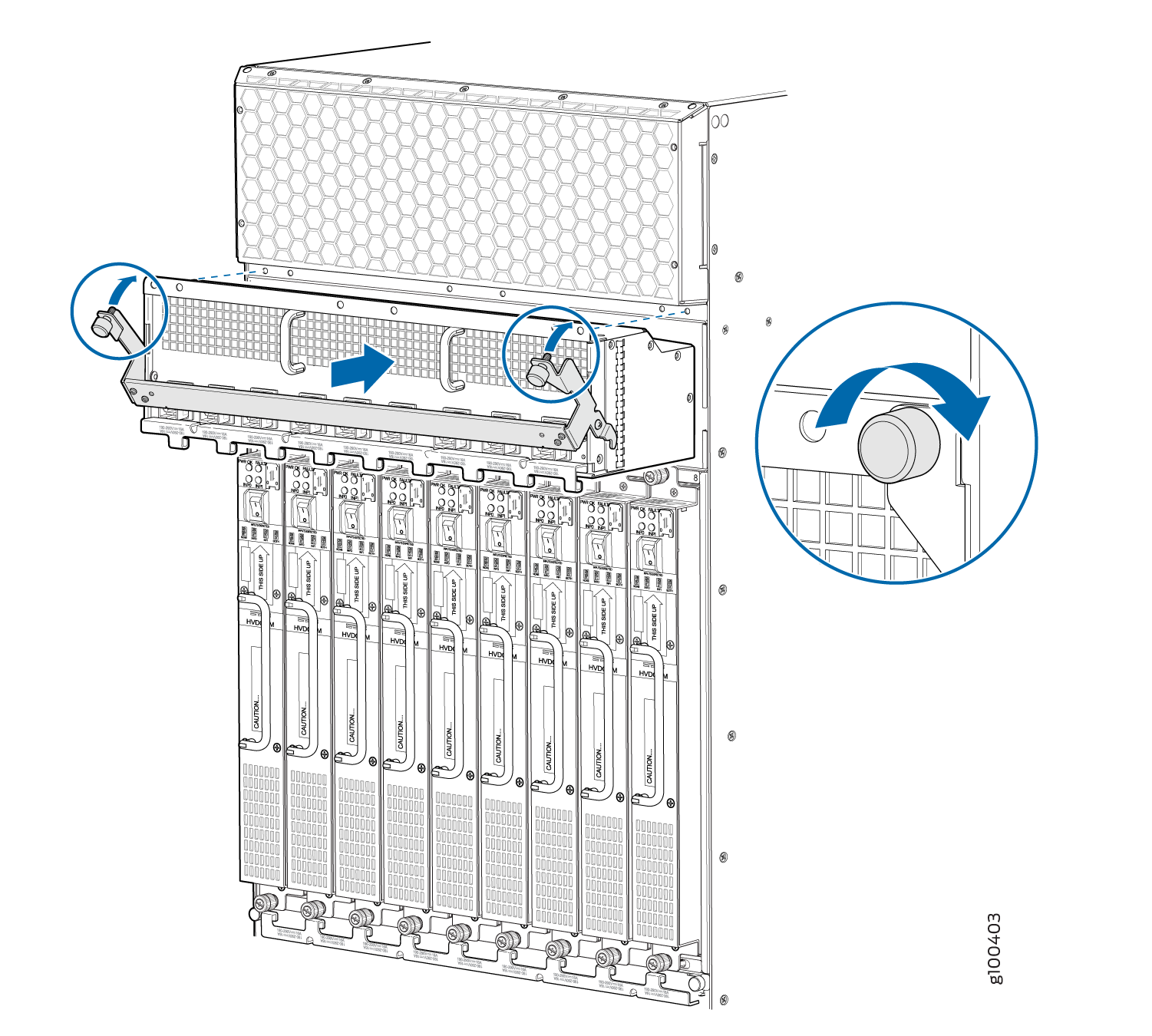
To install a universal HVAC/HVDC power distribution module (PDM) in an MX2000 Router:
- While holding both handles, guide the PDM until the locking
levers are inserted into the chassis. With both hands push the locking
levers simultaneously until the PDM is fully seated into the chassis
(see Figure 44).Figure 44: Installing an MX2000 Router Universal (HVAC/HVDC) Power Distribution Module
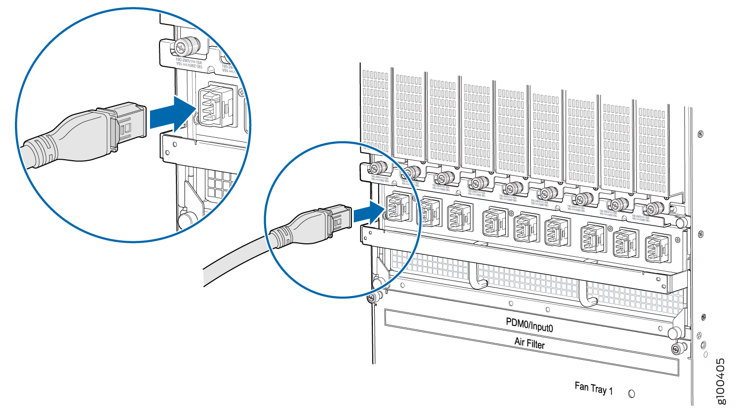
- Starting at one end of the PDM, plug the power cords into
the power sockets on the PDM. Press the latch on the side of the power
cable before pushing it in. Apply slight pressure so that the power
cord is firmly seated in the power socket until you feel it engage.
As you plug in each power cord, the power LED for the socket lights
up green. See Figure 45.Figure 45: Plugging the Universal (HVAC/HVDC) Power Cord an MX2000 Router
Removing an MX2000 Router High-Voltage Second Generation Universal (HVAC/HVDC) Power Distribution Module
Before you remove a PDM, be aware of the following:
The minimum number of PDMs must be present in the router at all times while it is operating.
Depending on whether you are connecting to AC or DC power, these warnings apply to the universal HVAC/HVDC power distribution module (PDM):
Before performing DC power procedures, disconnect all power sources. To ensure that all power is off, locate the circuit breaker on the panel board that services the DC circuit, switch the circuit breaker to the OFF position, and tape the switch handle of the circuit breaker in the OFF position.
These warnings apply to the HVAC/HVDC universal PDM:
Before performing AC power procedures, disconnect all power sources. To ensure that all power is OFF, locate the circuit breaker on the panel board that services the AC circuit, switch the circuit breaker to the OFF position, and tape the switch handle of the circuit breaker in the OFF position.
Before working on the device or near power supplies, unplug all the power cords from an AC-powered device.
To maintain proper cooling and prevent thermal shutdown of the operating power supply unit, each PDM slot must contain either a PDM or a blank panel. If you remove a PDM, you must install a replacement PDM or a blank panel shortly after the removal.
After powering off a PDM, wait at least 60 seconds before turning the circuit breaker back on.
- Starting at one end of the PDM, unplug all the power cords.
Press the latch on the side of the power cable before pulling it out.
See Figure 46.Figure 46: Unplugging the Universal HVAC/HVDC Power Cord an MX2000 Router
- Loosen the two captive screws on the locking levers, and
pull away from the chassis. See .Note:
For the MX2020 Router, pull down the PDM3/Input1 and PDM1/Input1 locking levers to release the PDM from the chassis, and pull up the PDM0/Input0 and PDM2/Input0 locking levers to release the PDM from the chassis.
Note:For the MX2010 and MX2008 Routers, pull down the PDM1/Input1 locking levers to release the PDM from the chassis, and pull up the PDM0/Input0 locking levers to release the PDM from the chassis.
Figure 47: Removing a Universal (HVAC/HVDC) PDM from an MX2020 Router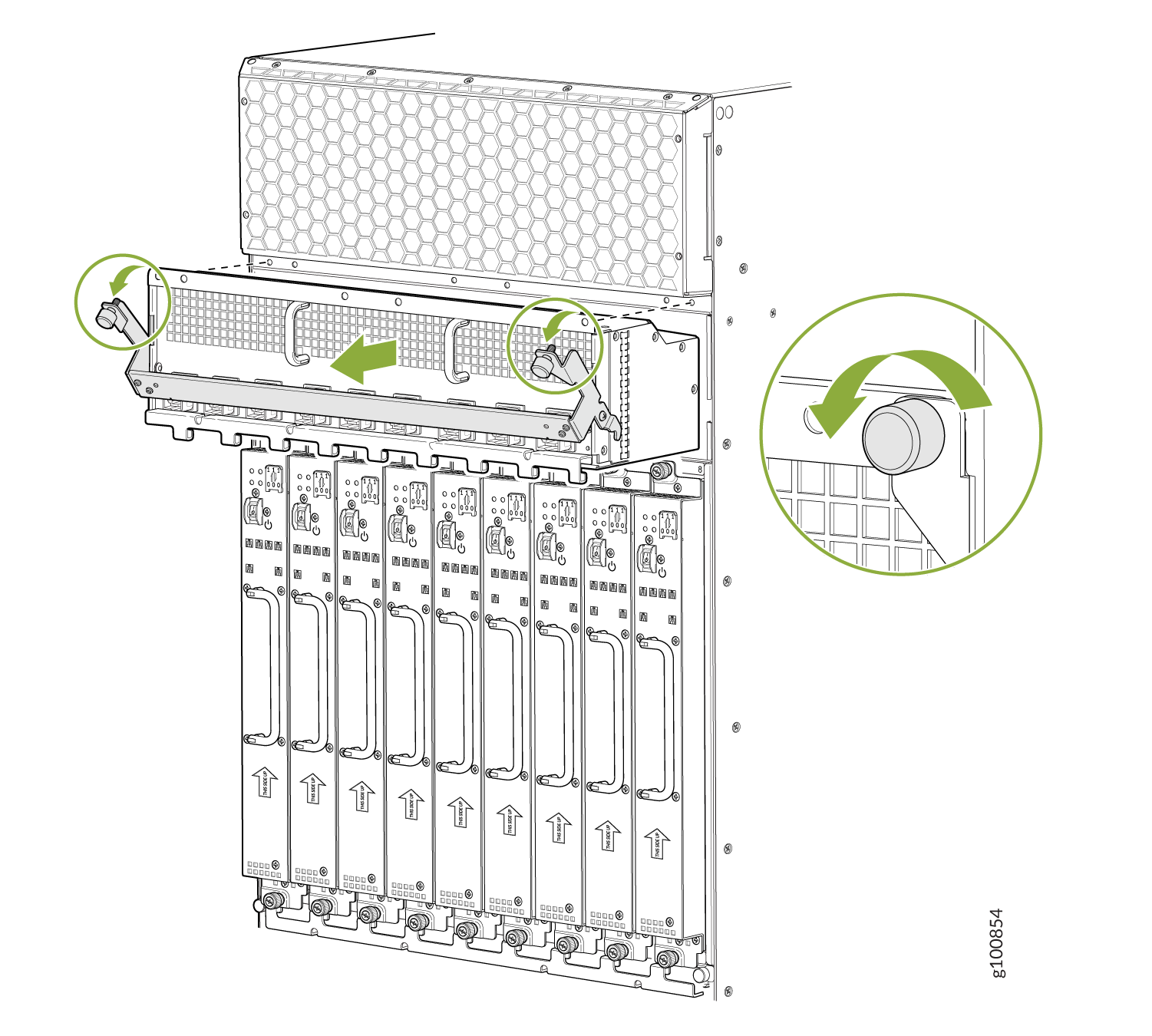 Figure 48: Removing a Universal (HVAC/HVDC) PDM from an MX2010 Router
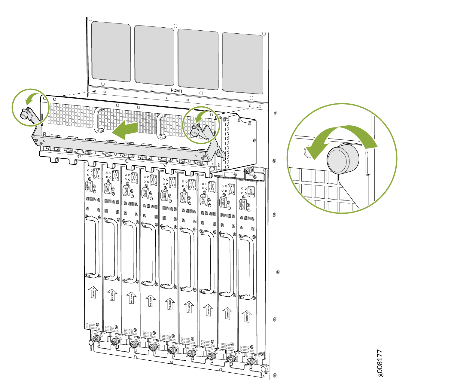 Figure 49: Removing a Universal (HVAC/HVDC) PDM from an MX2008 Router