MX10004 System Overview
This chapter describes the Juniper® Networks MX10004 Universal Router, its hardware components, the CLI terms that match terms in this user documentation, and the Junos OS software that runs the MX10004 router.
MX10004 Hardware Overview
The MX10004 router is the most compact, high-density, and power-efficient modular router in the MX10000 line of modular packet-routing transport routers. At only 7 U in height, the MX10004 is designed for today’s space-constrained facilities. Like the larger MX10000 routers, the MX10004 supports Juniper Networks’ 400-Gigabit Ethernet (GbE) architecture with inline Media Access Control Security (MACsec) on all ports for point-to-point security on Ethernet links.
The MX10004 provides 1-Gigabit Ethernet, 10-Gigabit Ethernet, 25-Gigabit Ethernet, 40-Gigabit Ethernet, 50-Gigabit Ethernet, 100-Gigabit Ethernet, or 400-Gigabit Ethernet modular solutions that support up to 38.4 terabits per second (Tbps) of throughput. The MX10004 power system and the Routing Control Board (RCB) provide redundancy and resiliency.
- Benefits
- Chassis Description
- Switch Fabric Boards
- Routing and Control Board
- Line Cards
- Cooling System
- Power Supplies
- Software
Benefits
The MX10004 is a small-footprint complement to the larger MX10000 modular chassis, with these benefits:
-
Ease of deployment—The MX10004 features a compact 7-U modular chassis for sites with limited space or power.
-
Modular, flexible design—The MX10004 router uses the custom silicon line cards (2.4 Tbps, 480 Gbps, and 9.6 Tbps throughput) and power supplies found in the larger MX10000 modular chassis.
-
Always-on infrastructure base—The MX10004 is engineered with full hardware redundancy for power and host subsystems—Routing and Control Boards (RCBs)—allowing service providers to meet stringent service-level agreements across the core.
-
Nondisruptive software upgrades—The Junos OS operating system on MX10004 supports high availability (HA) features such as graceful Routing Engine switchover (GRES) and nonstop active routing (NSR).
Chassis Description
The MX10004 router is 7-U tall. You can install up to six MX10004 routers in a standard 42-U rack with adequate cooling and power. All key MX10004 router components are field-replaceable units (FRUs). Figure 1 illustrates the key components visible from the front of the chassis, Figure 2 illustrates the components that are visible from the rear of the chassis, and Figure 3 illustrates the components that are internal to the chassis and are accessible after removing the fan trays.
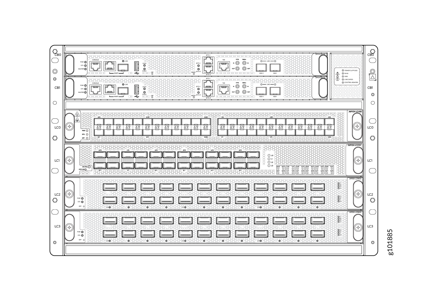
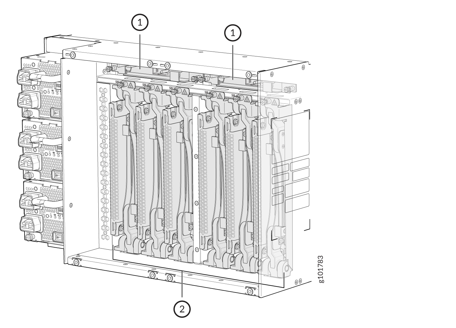
1 — Fan tray controllers | 2 — Switch Fabric Boards (SFBs) |
Switch Fabric Boards
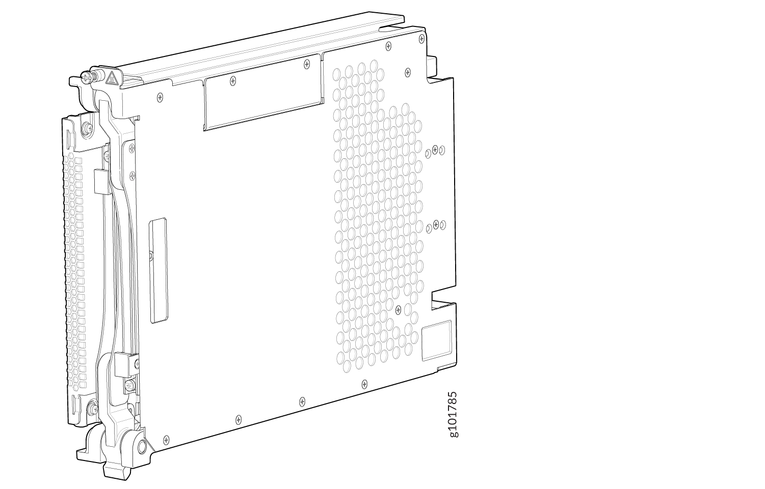
Switch Fabric Boards (SFBs) create the switch fabric for the MX10004. Each SFB has a set of connectors to mate the line cards and the Routing and Control Board (RCB) to the switch fabric. See Figure 4 for an example of the JNP10004-SF2 Switch Fabric Board.
For the MX10004 switch fabric, three SFBs provide reduced switching functionality to an MX10004 router. Six SFBs provide full throughput. You install the SFBs between the line cards and the fan trays inside the chassis. Each MX10004 SFB has four connectors. Each connector matches up with a line card slot, eliminating the need for a backplane.
You can order the MX10004 with different SFB configurations that enable you to grow your system as needed. See MX10004 Components and Configurations.
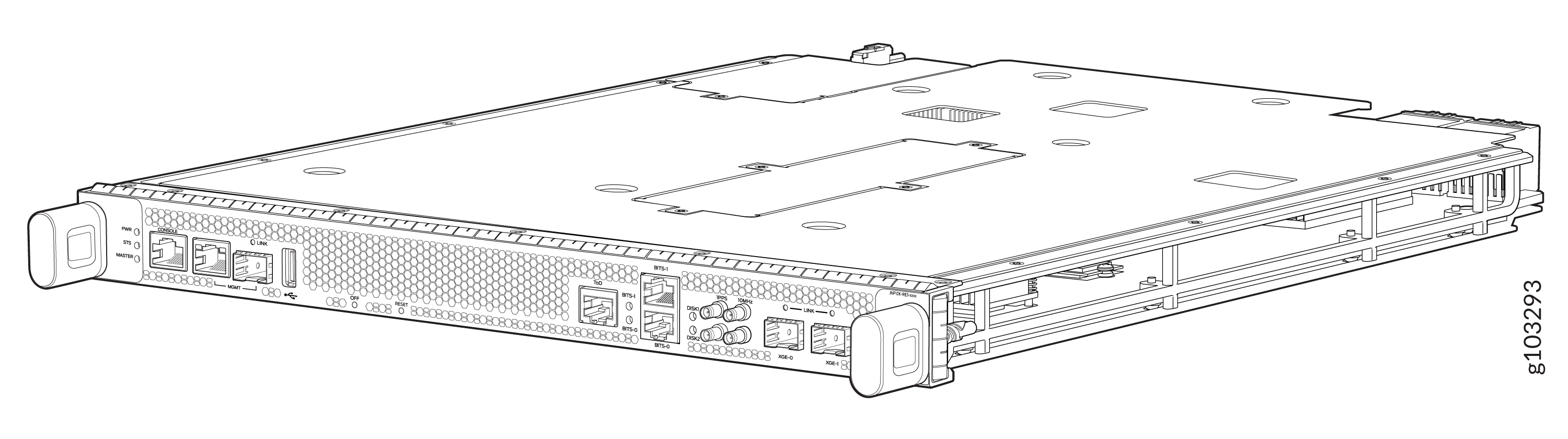
Routing and Control Board
The Routing and Control Board (RCB) contains a Routing Engine and is responsible for system management and system control in the MX10004. See MX10004 Routing and Control Board Components and Descriptions. RCBs are field-replaceable units (FRUs) that you install in the front of the chassis in the slots labeled CB0 and CB1.
The supported models of RCB for JNP10004-SF2 fabric systems are as follows:
-
JNP10K-RE3, 128 gigabytes of memory
-
JNP10K-RE3-LT, 128 gigabytes of memory
-
JNP10K-RE3-256, 256 gigabytes of memory
-
JNP10K-RE3LT256, 256 gigabytes of memory
-
JNP10K-RE1, 64 gigabytes of memory
-
JNP10K-RE1-LT, 64 gigabytes of memory
-
JNP10K-RE1-128, 128 gigabytes of memory
.
All the four variants of JNP10K-RE3 (JNP10K-RE3, JNP10K-RE3-LT, JNP10K-RE3-256, and JNP10K-RE3LT256) have the same form factor.
The MX10004-BASE configuration has a single RCB. The fully redundant configurations have two RCBs. The RCB also contains Precision Time Protocol (PTP) ports and four Media Access Control Security (MACsec) capable ports. See MX10004 Components and Configurations.
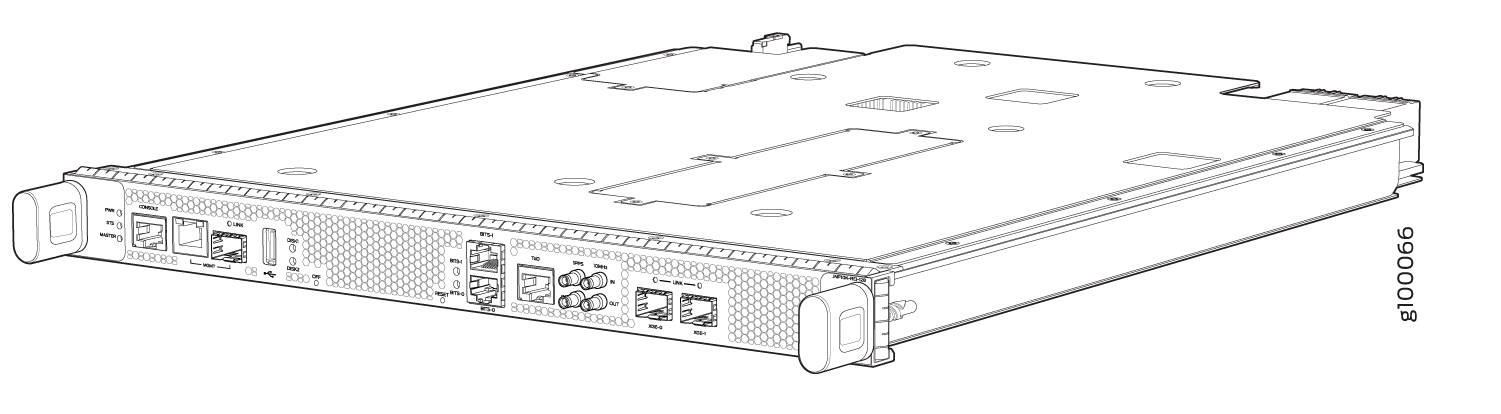
The MX10004-BASE configuration has a single RCB. The fully redundant configurations have two RCBs. The RCB also contains Precision Time Protocol (PTP) ports and four Media Access Control Security (MACsec) capable ports. See MX10004 Components and Configurations.
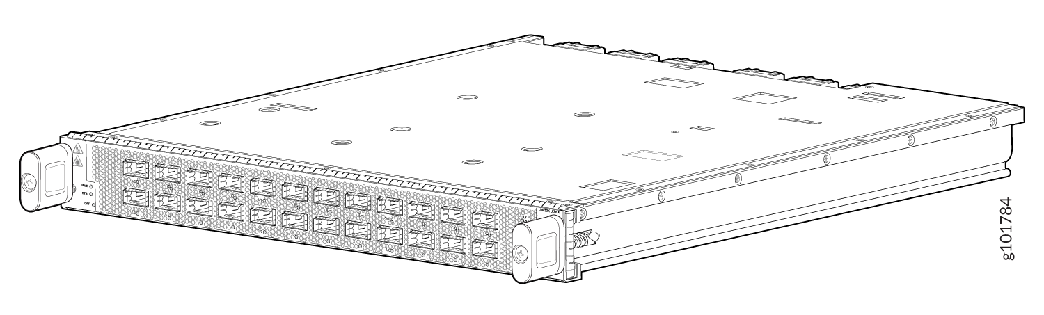
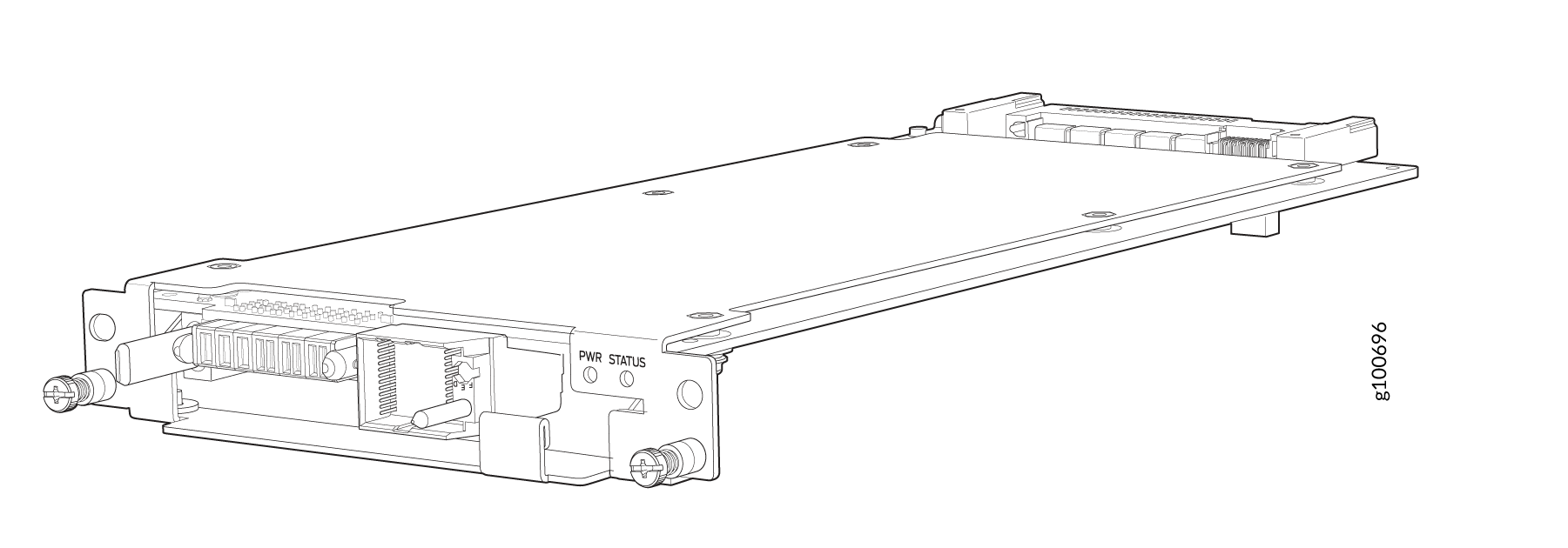
Line Cards
The MX10004 has four horizontal line card slots. The line cards combine a Packet Forwarding Engine and Ethernet interfaces enclosed in a single assembly. The MX10004 line card architecture is based on a number of identical, independent Packet Forwarding Engine slices. Line cards are FRUs that you can install in the line card slots labeled 0 through 3 (top to bottom) on the front of the chassis. All line cards are hot-removable and hot-insertable.
The MX10004 supports the following line cards:
See Figure 7 for an example of an MX10004 line card.
Cooling System
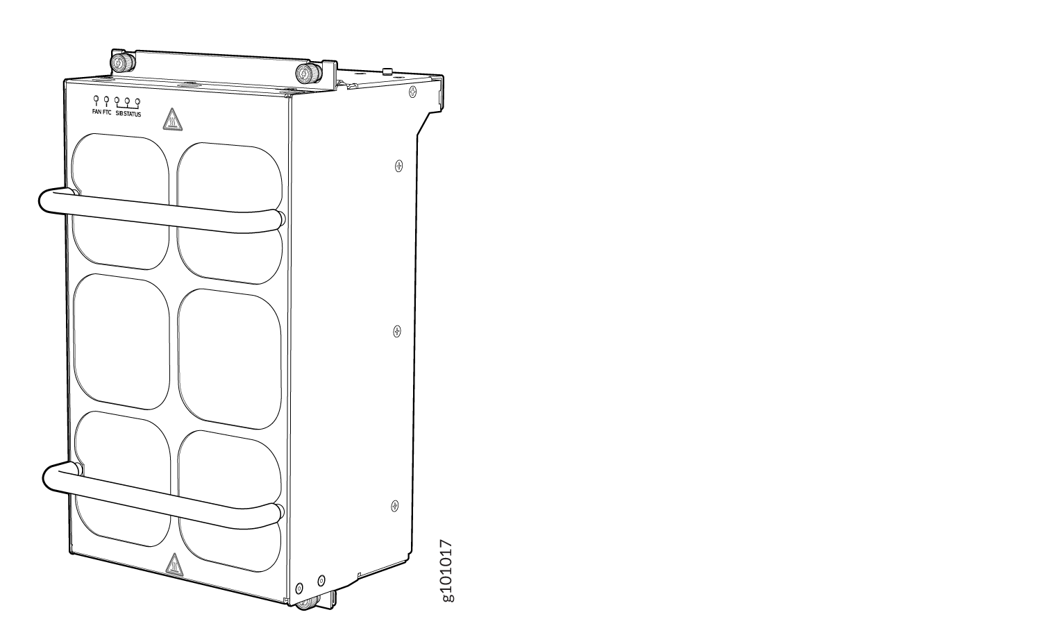
The cooling system in an MX10004 consists of two fan trays (see Figure 9) and two fan tray controllers (see Figure 10).
The JNP10004-FAN3 is the latest fan tray which uses powerful fans offering higher airflow within the system than its predecessor fan trays. The JNP10004-FAN3 fan tray also supports higher operating temperature so as not to affect the reliability of the fans.
The JNP10004-FAN3 fan tray contains an array of six fan modules, each with two counter-rotating fans. JNP10004-FAN3 fan tray operates as a single hot-removable and hot-insertable field-replaceable unit (FRU). The fan trays are installed vertically on the rear of the chassis and provide front-to-back chassis cooling. See MX10004 Cooling System. The JNP10004-FAN3 consumes the same amount of power as JNP10004-FAN2.
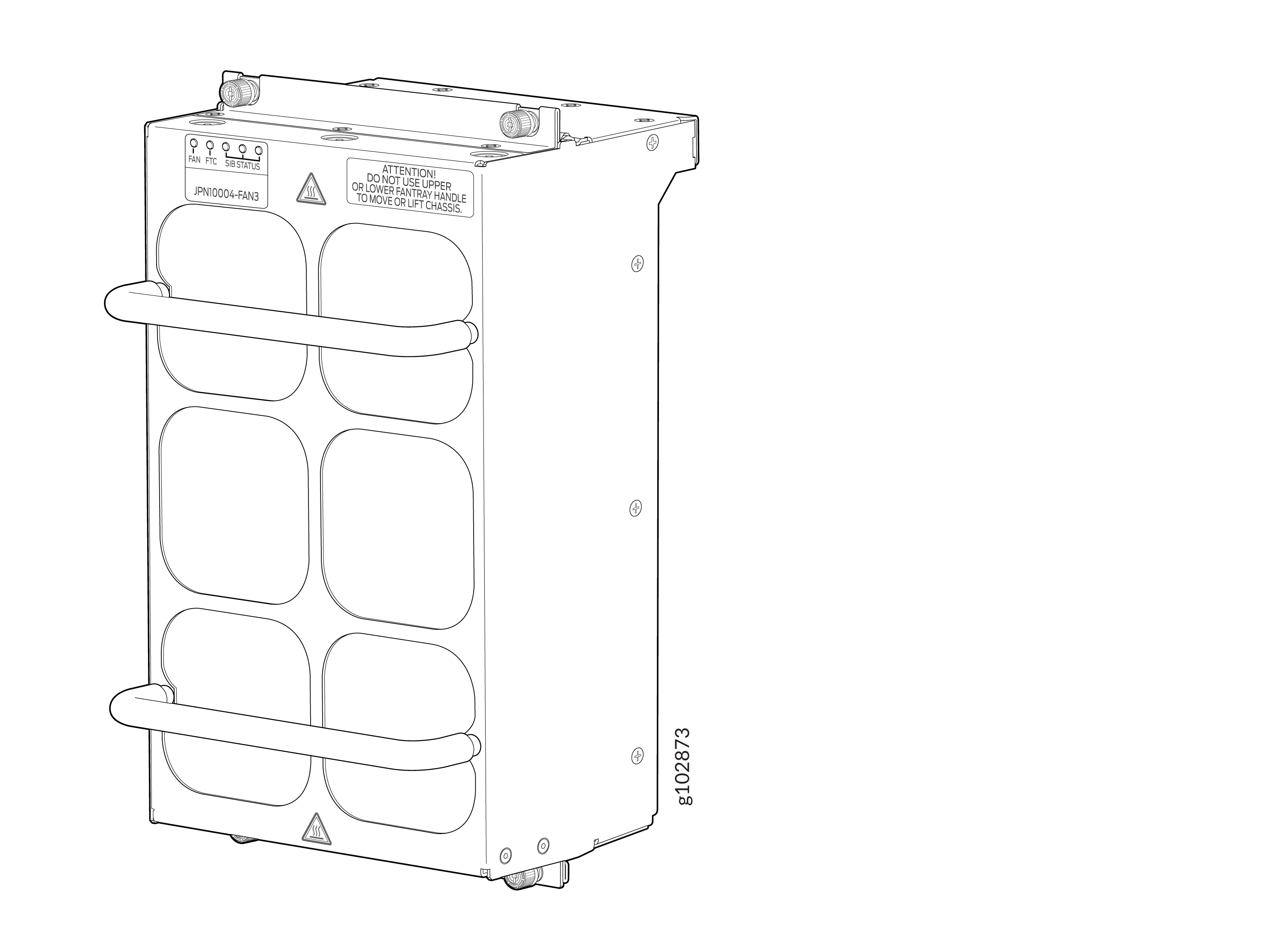
Each JNP10004-FAN3 fan tray has a corresponding fan tray controller, JNP10004-FTC3. See Figure 10.
The JNP10004-FAN2 fan tray contains an array of six fans and operates as a single hot-removable and hot-insertable field-replaceable unit (FRU). You install the fan trays vertically on the rear of the chassis to provide front-to-back chassis cooling. See MX10004 Cooling System.
Each JNP10004-FAN2 fan tray has a corresponding fan tray controller, JNP10004-FTC2. See Figure 10.
Power Supplies
The MX10004 routers support AC, DC, high-voltage alternating current (HVAC), and high-voltage direct current (HVDC) through the following power supplies:
-
JNP10K-PWR-AC3
-
JNP10K-PWR-AC2
-
JNP10K-PWR-DC3
-
JNP10K-PWR-DC2
-
JNP10K-PWR-AC3H
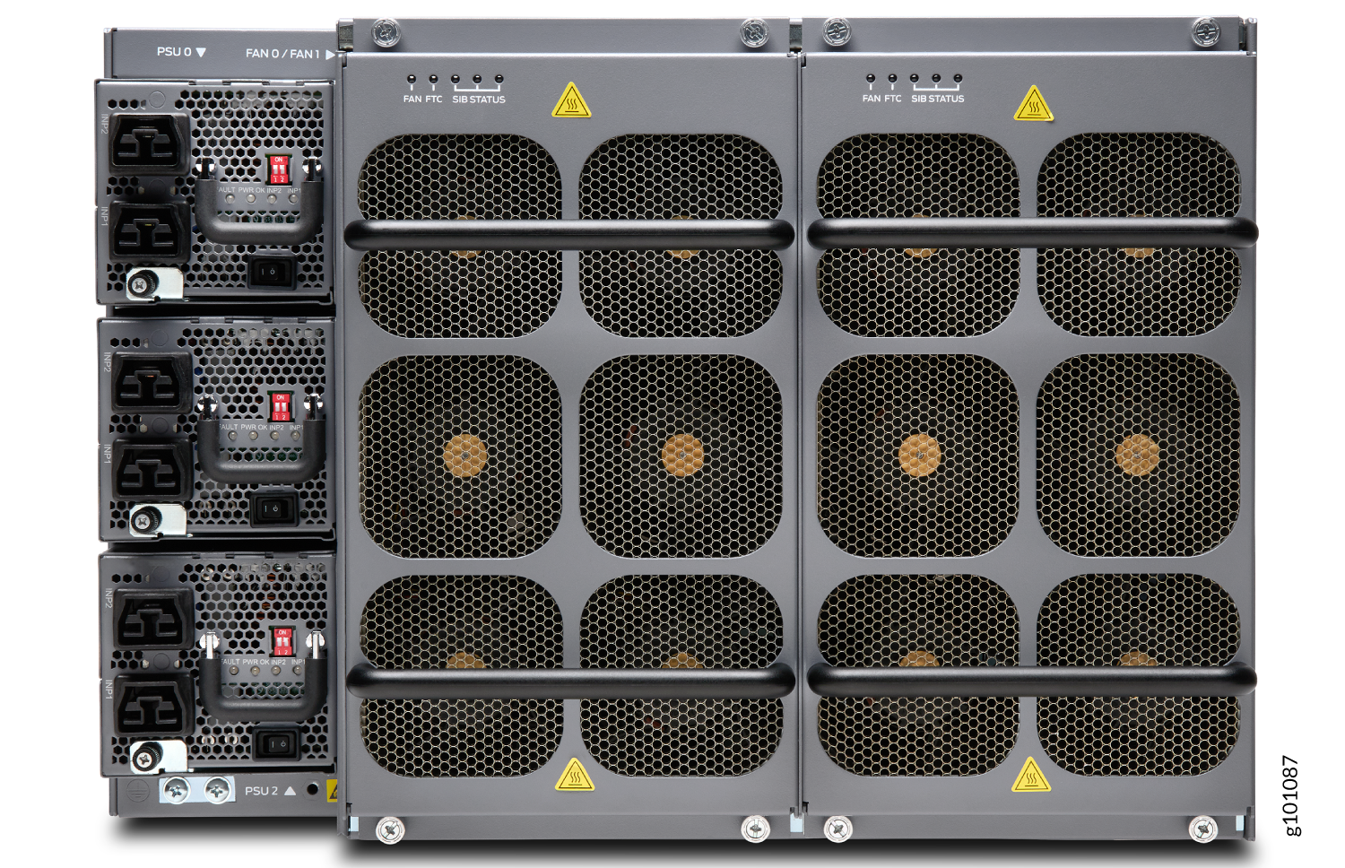
Power supplies for the MX10004 are load-sharing, hot-removable, hot-insertable FRUs. The router operates with three power supplies. Each power supply has an internal fan for cooling. You can install the power supplies in any slot. See Figure 11, Figure 12, Figure 13, Figure 14, and Figure 15.
Avoid mixing power supply models in the same chassis in a running environment.
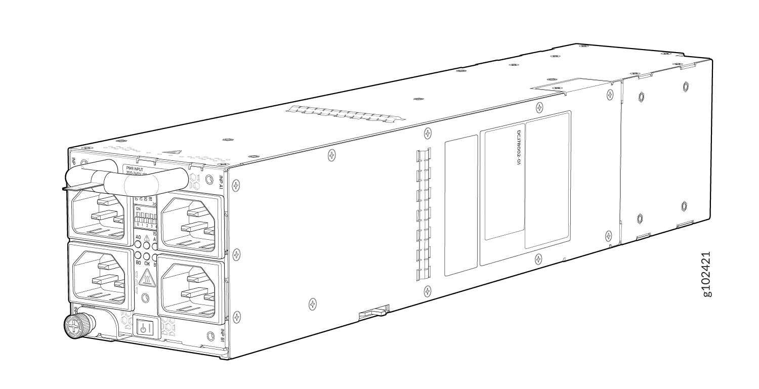
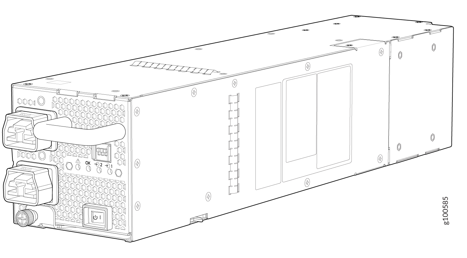
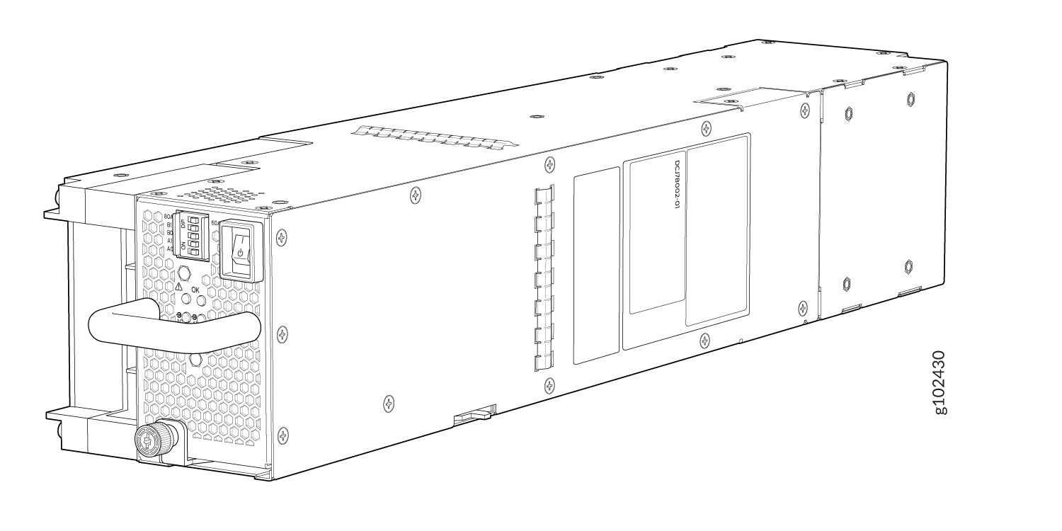
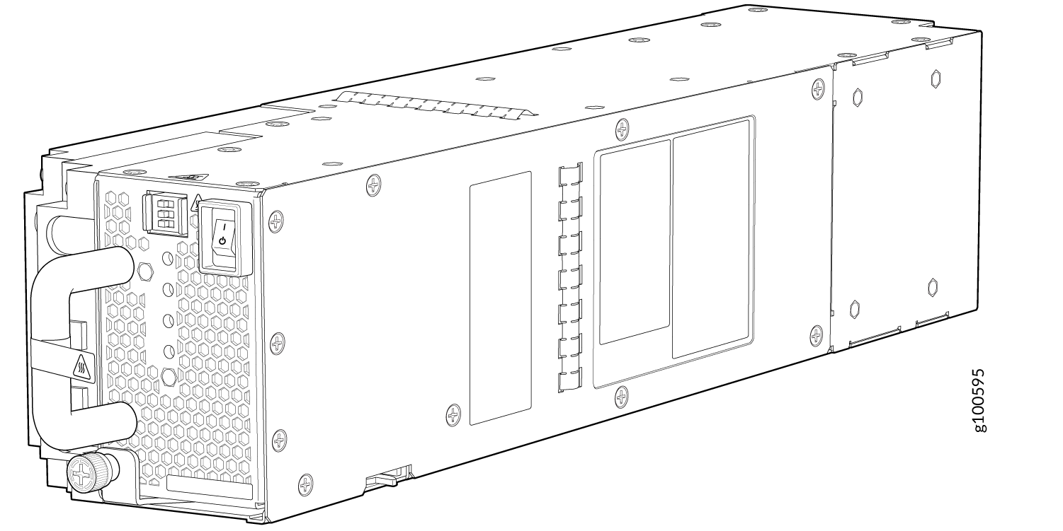
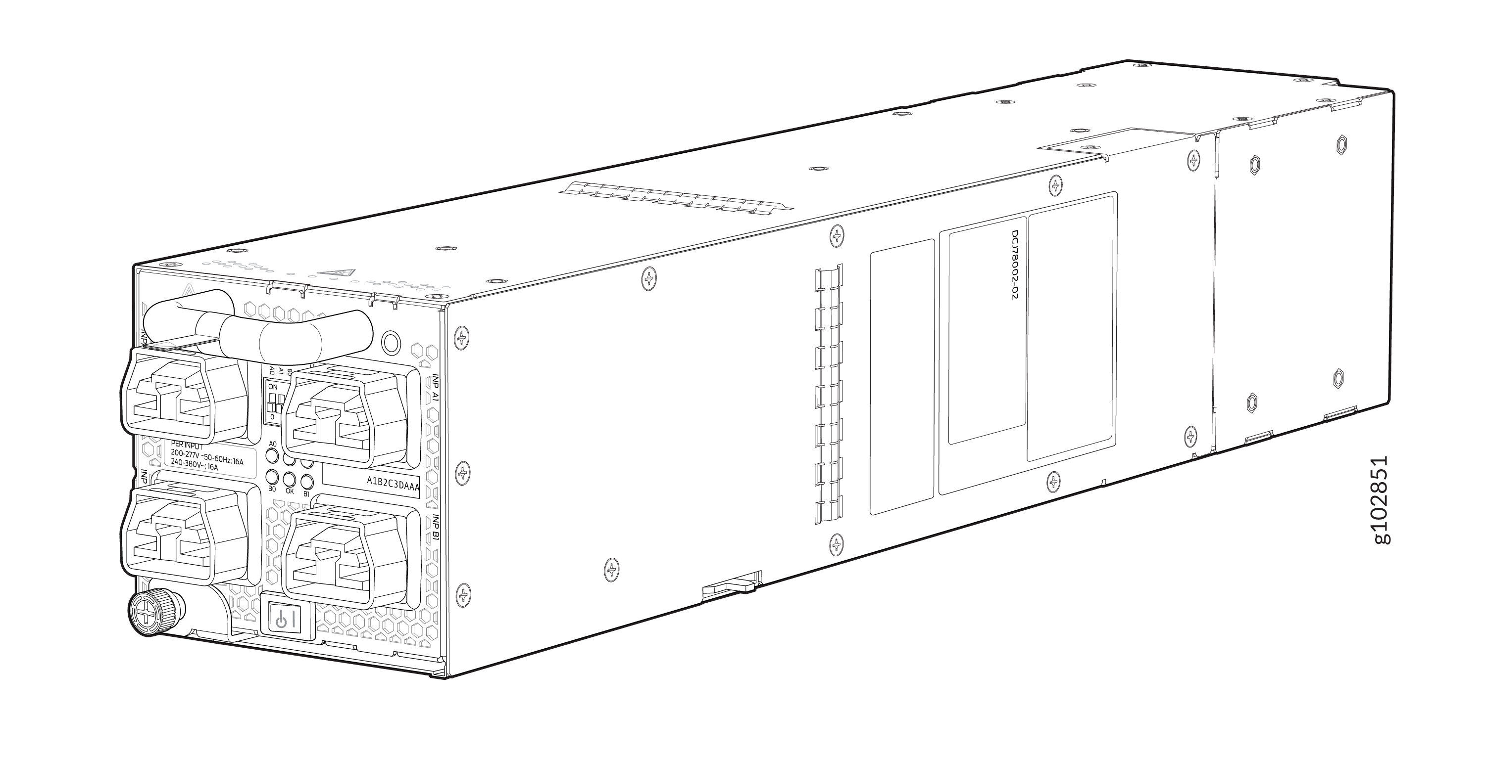
Table 1 provides an overview of the differences between the power supplies.
|
Power Supply Model |
Input Type |
Wattage |
|---|---|---|
|
JNP10K-PWR-AC3 |
AC |
|
|
JNP10K-PWR-AC2 |
AC, HVAC, or HVDC |
5000 W, single feed; 5500 W, dual feed |
|
JNP10K-PWR-DC3 |
DC only |
|
|
JNP10K-PWR-DC2 |
DC only |
2750 W, single feed; 5500 W, dual feed |
|
JNP10K-PWR-AC3H |
HVAC or HVDC |
|
Software
The Juniper Networks MX10004 Universal Routing platform runs on the Junos OS 22.3R1 operating system.
MX10004 Components and Configurations
MX10004 Configurations
Table 2 lists the hardware configurations for an MX10004 modular chassis and the components included in each configuration.
|
Router Configuration |
Configuration Components |
|---|---|
|
MX10004-BASE |
|
|
MX10004-PREMIUM |
|
|
MX10004-3F-BASE |
|
|
MX10004-4F-PREM |
|
In MX10004-3F-BASE and MX10004-4F-PREM configurations with MX10K-LC9600 line cards installed the fabric capacity is only 52% and 69% respectively. When you try to use all the ports on the line cards, it leads to fabric over-subscription. To prevent fabric over-subscriptions, you must use only the odd-numbered ports or only the even-numbered ports.
You must order line cards and the cable management system separately. They are not part of the base or redundant configuration.
If you want to purchase additional power supplies (AC, DC, HVAC, or HVDC), SFBs, or RCBs for your router configuration, you must order them separately.
MX10004 Component Redundancy
The MX10004 router is designed so that no single point of failure can cause the entire system to fail. The following major hardware components in the redundant configuration provide redundancy:
-
Routing and Control Board (RCB)—The RCB consolidates the Routing Engine function with the control plane function in a single unit. The MX10004 router can have one or two RCBs. When two RCBs are installed, one functions as the primary RCB, and the other functions as the backup RCB. If the primary RCB (or either of its components) fails, the backup RCB can take over as primary. See MX10004 Routing and Control Board Components and Descriptions.
-
Switch Fabric Boards (SFBs)—The MX10004 has six SFB slots for the JNP10004-SF2 SFBs. The switch fabric requires a minimum of three SFBs to provide the reduced switching functionality to an MX10004 router. You can achieve 5+1 SFB redundancy, only when the MX10004 router is populated with MX10K-LC2101 or MX10K-LC480 line cards or a mix of the two line cards. You must install all six SFBs for MX10K-LC9600 line card support.
-
Power supplies—The system requires two power supplies for minimum operation. If you install three power supplies, the third power supply provides 2+1 redundancy. If one power supply fails in a fully redundant system, the other power supplies can provide full power to the MX10004 router indefinitely.
With the power supply redundancy, when one power supply fails, it does not cause line cards to go offline. Only the
No Redundant Powerminor alarm is raised. You can disable this alarm by using theset chassis no-psu-redundancycommand.Line cards can go offline depending on the total chassis power available at that time. When an line card goes offline due to insufficient power,
Power Budget: Insufficient Powermajor alarm is raised.The MX10004 router also supports power source redundancy. Four sets of lugs are provided for the JNP10K-PWR-DC2 or JNP10K-PWR-DC3 cables, and two AC power cords are provided for each JNP10K-PWR-AC2 or JNP10K-PWR-AC3 power supply.
-
Cooling system—The MX10004 has two fan trays, both of which are controlled by the corresponding fan tray controllers. If one of the fans in a JNP10004-FAN2 or JNP10004-FAN3 fan tray fails, under most conditions the fan tray rebalances the remaining fans to continue. The fan tray continues to operate indefinitely and provide sufficient cooling even when a single rotor fails in a fan, provided that the room temperature is within the operating range. See MX10004 Cooling System.
MX10004 Hardware and CLI Terminology Mapping
This topic describes the hardware terms used in MX10004 router documentation and the corresponding terms used in the Junos OS CLI. See Table 3.
|
Hardware Item (CLI) |
Description (CLI) |
Value (CLI) |
Item in Documentation |
Additional Information |
|---|---|---|---|---|
|
Chassis |
MX10004 |
– |
Router chassis |
|
|
Fan tray |
JNP10004-FAN2 JNP10004-FAN3 |
The variable n is a value in the range of 0–11. The value corresponds to the individual fan number in the fan tray. |
Fan tray |
|
|
FPC (n) |
Abbreviation for the Flexible PIC Concentrator (FPC) On MX10004, an FPC is equivalent to a line card. |
The variable n is a value in the range of 0–3 for the MX10004. The value corresponds to the line card slot number in which the line card is installed. |
Line card |
|
|
PIC (n) |
Abbreviated name of the Physical Interface Card (PIC). |
The variable n is a value in the range of 0–5. |
– |
|
|
PEM (n) |
Abbreviation for power supply module One of the following:
|
The variable n is a value in the range of 0–2. The value corresponds to the power-supply slot number. |
AC, DC, or HVDC power supply |
One of the following: |
|
Routing Engine |
RE (n) |
The variable n is a value in the range of 0–1. Multiple line items appear in the CLI if more than one RCB is installed in the chassis. |
RCB |
MX10004 Routing and Control Board Components and Descriptions |
|
SFB (n) |
This field indicates:
|
The variable n is a value in the range of 0–5. |
Fabric plane |
|
|
Xcvr (n) |
Abbreviation for the transceiver |
The variable n is a value equivalent to the number of the port in which the transceiver is installed. |
Optical transceivers |