MX10004 Cooling System
The MX10004 cooling system components work together to keep all components within the acceptable temperature range. If the maximum temperature specification is exceeded and the system cannot be adequately cooled, the Routing and Control Board (RCB) shuts down some or all of the hardware components.
MX10004 Cooling System and Airflow
The cooling system in an MX10004 chassis consists of dual fan trays (JNP10004-FAN2 or JNP10004-FAN3) with matching dual fan tray controllers (JNP10004-FTC2 or JNP10004-FTC3). Each fan tray requires a companion fan tray controller to be installed and operational to be hot-insertable and hot-removable.
Fan Tray
The JNP10004-FAN3 fan tray contains an array of six fans modules, each with two counter-rotating fans. JNP10004-FAN3 fan tray operates as a single hot-removable and hot-insertable field-replaceable unit (FRU). The fan trays are installed vertically, side by side, next to the power supplies on the rear of the chassis and provide front-to-back chassis cooling. You can remove or insert the fan trays by using the two handles provided on the face plate, See Figure 1 and Figure 3.
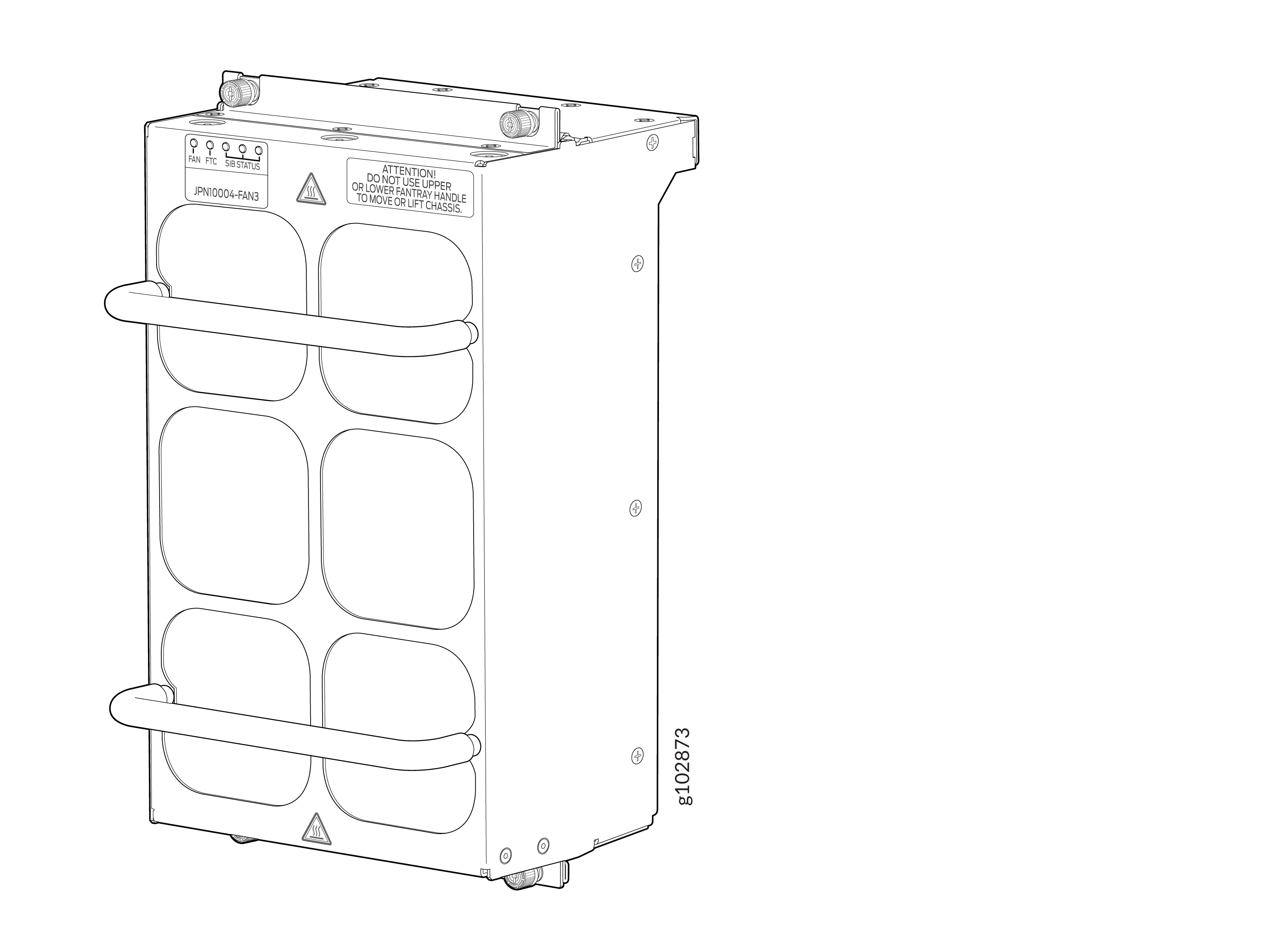
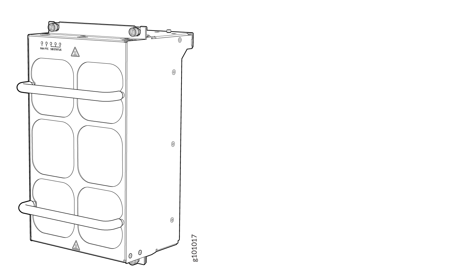
The JNP10004-FAN2 fan tray contains an array of internal fans, a non-removable control board, and LEDs.
The two fan trays install vertically, side by side, next to the power supplies on the rear side of the chassis. Two handles on each front faceplate facilitate handling of the fan tray. See Figure 2 and Figure 3.
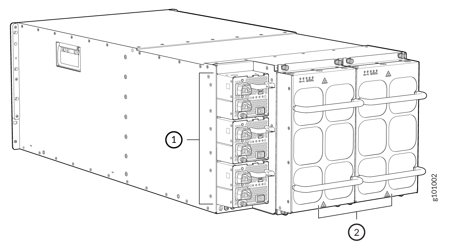
1 — Power supplies | 2 — Fan trays |
See Table 1 for the physical specifications of the fan trays.
|
Specification |
JNP10004-FAN3 |
JNP10004-FAN2 |
|---|---|---|
|
Corresponding fan tray controller model |
JNP10004-FTC3 |
JNP10004-FTC2 |
|
Number of fan modules per fan tray |
6 |
6 |
|
Number of fan modules per chassis |
12 |
12 |
|
Fan numbering |
0 through 11 |
0 through 11 |
|
Volume flow at 100 percent |
1100 CFM for both fan trays (550 CFM per tray) |
948 CFM for both fan trays |
|
Height |
12.09 in. (30.7 cm) |
12.08 in. (30.68 cm) |
|
Width |
6.6 in. (16.8 cm) |
6.6 in. (16.8 cm) |
|
Depth |
5.88 in. (14.94 cm) without handles |
5.5 in. (13.97 cm) without handles, 6.85 in. (17.4 cm) with handles |
|
Weight |
14.4 lb (6.53 kg) |
9.8 lb (4.45 kg) |
The fan tray operates as a single unit. If an individual fan in the tray fails, you must replace the entire fan tray. However, the fan tray continues to operate indefinitely and provides sufficient cooling even when a single fan rotor fails. The fan tray operates indefinitely provided that the room temperature is within the operating range.
If you want to replace an existing fan tray while the router is running, remove only one fan tray. The router continues to operate for a limited time with a single operating fan tray without triggering a thermal alarm.
To avoid triggering a thermal alarm, remove only one fan tray while the router is operating.
Fan Tray Controller
The MX10004 supports two fan tray controllers to provide the control logic and power to hot-insert and hot-remove a fan tray
-
JNP10004-FTC2—Supports model JNP10004-FAN2 fan tray; see .
-
JNP10004-FTC3—Supports JNP10004-FAN3 fan tray and JNP10004-FAN2 fan trays; see Figure 4.
Table 2: Fan Tray Controller - Fan Tray Compatability Fan Tray Controller Compatible Fan Tray JNP10004-FTC2 JNP10004-FAN2 JNP10004-FTC3 JNP10004-FAN3, JNP10004-FAN2 Warning:Do not mix the fan tray controller models. Use only the supported fan tray model for each fan tray controller. See Table 3.
Do not use JNP10004-FTC2 with JNP10004-FAN3 fan tray.
Figure 4: Fan Tray Controller JNP10004-FTC2 or JNP10004-FTC3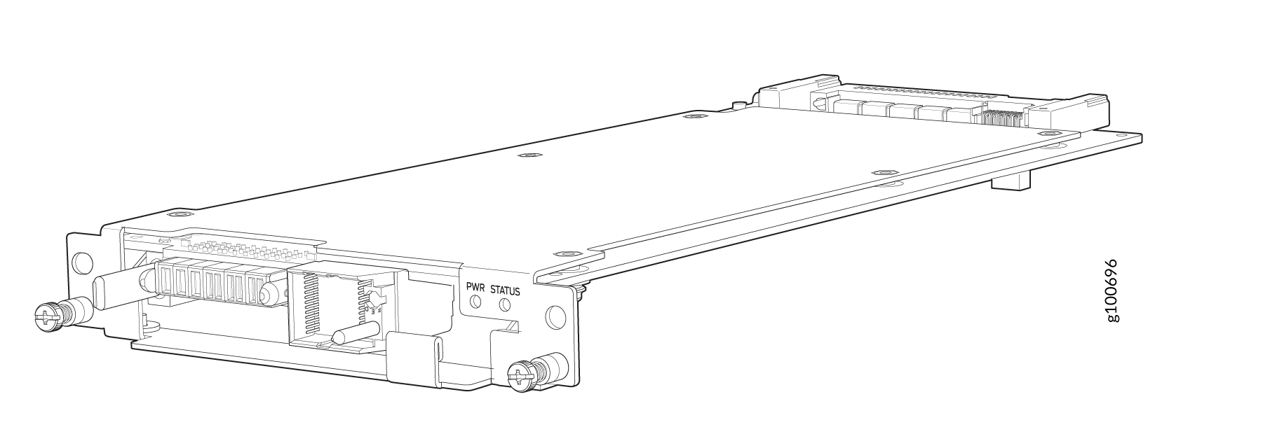
|
Specification |
JNP10004-FTC3 |
JNP10004-FTC2 |
|---|---|---|
|
Corresponding fan tray model |
JNP10004-FAN3 |
JNP10004-FAN2 |
|
Height |
1.5 in. (3.81 cm) |
1.5 in. (3.81 cm) |
|
Width |
6.5 in. (15.24 cm) |
6.5 in. (15.24 cm) |
|
Depth |
12.4 in. (31.5 cm) |
12.4 in. (31.5 cm) |
|
Weight |
1.1 lb (0.5 kg) |
1.1 lb (0.5 kg) |
The system continually monitors the temperature of critical parts across the chassis and
adjusts the chassis fan speed according to the temperature. Junos OS controls the fan
speed. Under normal operating conditions, the fans in the fan tray run at less than full
speed. If one fan tray controller fails or appears missing , the other fan tray controller
sets the fans to full speed. (A fan tray can appear to be missing when you replace an SFB,
for example.) The ability to modify fan speed enables the router to continue to operate
normally as long as the remaining fans cool the chassis sufficiently. Use the show
chassis fan command to see the status of individual fans and fan speed.
To determine the cooling of all the components in the system, use the show
chassis environment command.
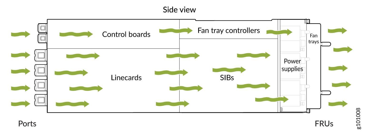
Airflow Direction in the MX10004
The air intake to cool the chassis is located on the port (line card) side of the chassis. Air flows into the chassis from the ports in the Routing and Control Boards (RCBs) and line cards, through the Switch Fabric Boards (SFBs), and exits from the fan trays and the power supplies. See Figure 5.
The fan tray continues to operate indefinitely and provide sufficient cooling even when a single rotor fails, provided the room temperature is within the operating range. You can check the status of fans by viewing the LEDs on each fan tray.
You cannot replace a single fan. If one or more fans fail, you must replace the entire fan tray.
In addition to the fans in the fan trays, an internal fan in each power supply also helps to cool components such as line cards.
MX10004 Fan Tray LEDs and Fan Tray Controller LEDs
Each fan tray has a set of LEDs, and each corresponding fan tray controller also has a set of LEDs.
Fan Tray LEDs
Each fan tray has a set of five LEDs that represent the status of the fans in the fan tray, the fan tray controller, and three of the Switch Fabric Boards (SFBs) that are installed behind the fan tray. The LEDs are located on the top left corner of each fan tray. Figure 6 shows the location of the LEDs on JNP10004-FAN2 and JNP10004-FAN3 fan trays.
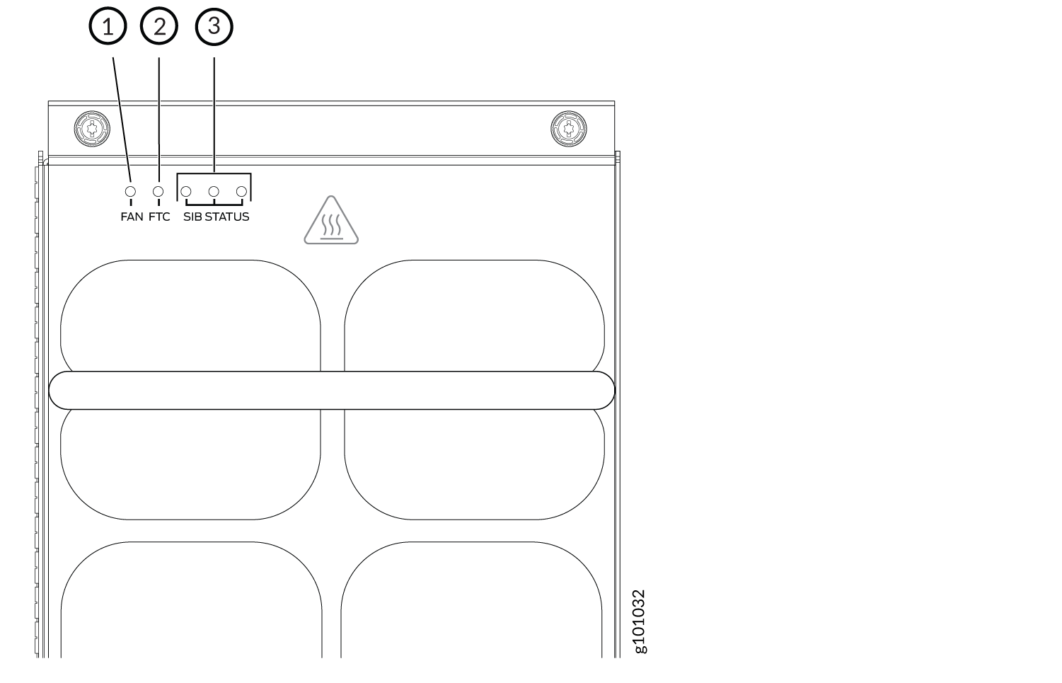
1 — Fan status LED | 3 — SFB status LEDs - The SIB STATUS LEDs on the left fan tray display the status of the three SFBs installed in SFB 0 through SFB 2 and the SIB STATUS LEDs on the right fan tray display the status of the three SFBs installed in SFB 3 through SFB 5. |
2 — Fan tray controller status LED |
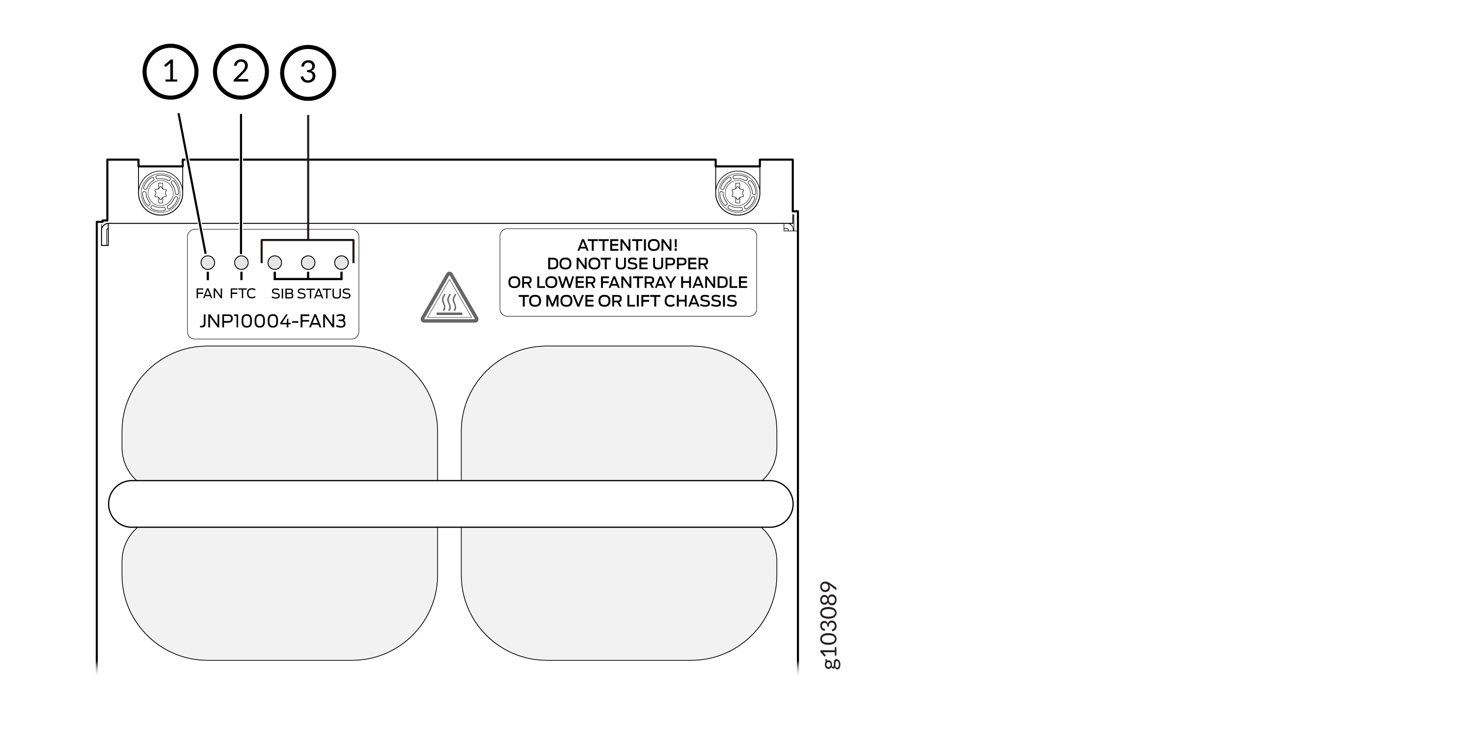
1 — Fan status LED | 3 — SIB status LEDs (SIB 0 through SIB 2 for the left fan tray and SIB 3 through SIB 5 for the right fan tray) |
2 — Fan tray controller status LED |
Table 4 describes the functions of the fan tray LEDs.
|
Name |
Color |
State |
Description |
|---|---|---|---|
|
FAN (fan status) |
Green |
On steadily |
All fans are operating normally. The system has verified that the fan tray is engaged, that the airflow is in the correct direction, and that all fans are operating correctly. |
|
Green |
Blinking |
The fan tray is starting. The fan tray is not ready. |
|
|
Amber |
Blinking |
An error has been detected in one or more fans in the fan tray. Replace the fan tray as soon as possible. Either the fan has failed or it has become disconnected. To maintain proper airflow through the chassis, leave the fan tray installed in the chassis until you are ready to replace it. |
|
|
Amber |
Blinking |
Beacon is enabled. |
|
|
None |
Off |
The fan is not receiving power from the fan tray controller. All fans are off. |
|
|
FTC (fan tray controller status) |
Green |
On steadily |
Power is on. The fan tray controller is online and is operating normally. |
|
Amber |
Blinking |
An error has been detected in the fan tray controller. Replace the fan tray controller as soon as possible. The fan tray controller is located behind the fan tray above the SFBs. To maintain proper airflow through the chassis, leave the fan tray installed in the chassis until you are ready to replace the fan tray controller. |
|
|
Amber |
Blipping |
Beacon is enabled. |
|
|
None |
Off |
The fan tray controller is not receiving power. |
|
|
SIB Status (SFB 0 status) |
Green |
On steadily |
The left-most SFB in the chassis is online. |
|
Amber |
Blinking |
An error has been detected in SFB 0. Replace the SFB as soon as possible. The SFB is located behind the left fan tray and is the left-most SFB in the chassis. To maintain proper airflow through the chassis, leave the fan tray installed in the chassis until you are ready to replace the SFB. |
|
|
Amber |
Blipping |
Beacon is enabled. |
|
|
None |
Off |
The SFB is offline. |
|
|
SIB Status (SFB 1 status) |
Green |
On steadily |
The center SFB behind the left fan tray is online. |
|
Amber |
Blinking |
An error has been detected in SFB 1. Replace the SFB as soon as possible. The SFB is located behind the left fan tray and is the middle SFB in the group of 3. To maintain proper airflow through the chassis, leave the fan tray installed in the chassis until you are ready to replace the SFB. |
|
|
None |
Off |
The SFB is offline. |
|
|
SIB Status (SFB 2 status) |
Green |
On steadily |
The right-most SFB behind the left fan tray is online. |
|
Amber |
Blinking |
An error has been detected in SFB 2. Replace the SFB as soon as possible. The SFB is located behind the left fan tray and is the right-most SFB in the group of 3. To maintain proper airflow through the chassis, leave the fan tray installed in the chassis until you are ready to replace the SFB. |
|
|
Amber |
Blipping |
Beacon is enabled. |
|
|
None |
Off |
The SFB is offline. |
|
|
SIB Status (SFB 3 status) |
Green |
On steadily |
The left-most SFB behind the right fan tray is online. |
|
Amber |
Blinking |
An error has been detected in SFB 3. Replace the SFB as soon as possible. The SFB is located behind the right fan tray and is the left-most SFB of the group of 3. To maintain proper airflow through the chassis, leave the fan tray installed in the chassis until you are ready to replace the SFB. |
|
|
Amber |
Blipping |
Beacon is enabled. |
|
|
None |
Off |
The SFB is offline. |
|
|
SIB Status (SFB 4 status) |
Green |
On steadily |
The center SFB behind the right fan tray is online. |
|
Amber |
Blinking |
An error has been detected in SFB 4. Replace the SFB as soon as possible. The SFB is located behind the right fan tray and is the middle SFB in the group of 3. To maintain proper airflow through the chassis, leave the fan tray installed in the chassis until you are ready to replace the SFB. |
|
|
Amber |
Blipping |
Beacon is enabled. |
|
|
None |
Off |
The SFB is offline. |
|
|
SIB Status (SFB 5 status) |
Green |
On steadily |
The right-most SFB behind the right fan tray is online. |
|
Amber |
Blinking |
An error has been detected in SFB 5. Replace the SFB as soon as possible. The SFB is located behind the right fan tray and is the right-most SFB in the group of 3. To maintain proper airflow through the chassis, leave the fan tray installed in the chassis until you are ready to replace the SFB. |
|
|
Amber |
Blipping |
Beacon is enabled. |
|
|
None |
Off |
The SFB is offline. |
Fan Tray Controller LEDs
The fan tray controller LEDs are visible only when the associated fan tray is removed. The fan tray controller LEDs are located on the right of the controller panel. Figure 8 shows the location of the LEDs on the JNP10004-FTC2 fan tray controller faceplate.
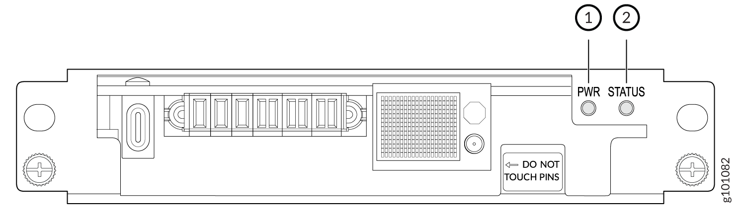
1 — Fan tray controller power | 2 — Fan tray controller status |
Table 5 describes the functions of the fan tray controller LEDs.
|
Name |
Color |
State |
Description |
|---|---|---|---|
|
PWR (fan tray controller power) |
Green |
On steadily |
The fan tray controller has power and is operating normally. |
|
Amber |
Blinking |
A power error has been detected in the fan tray controller. Replace the fan tray controller as soon as possible. To maintain proper airflow through the chassis, leave the fan tray installed in the chassis until you are ready to replace the fan tray controller. |
|
|
None |
Off |
The fan tray controller is not powered on or is not receiving power. |
|
|
STATUS (fan tray controller status) |
Green |
On steadily |
The fan tray controller is online and is operating normally. |
|
Amber |
Blinking |
An error has been detected in the fan tray controller. Replace the fan tray controller as soon as possible. To maintain proper airflow through the chassis, leave the fan tray installed in the chassis until you are ready to replace the fan tray controller. |
|
|
None |
Off |
The fan tray controller is not receiving power. |