MX10004 Routing and Control Board Components and Descriptions
MX10004 Routing and Control Board Description
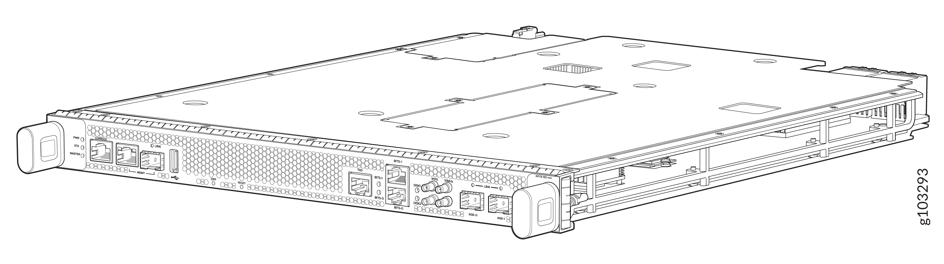
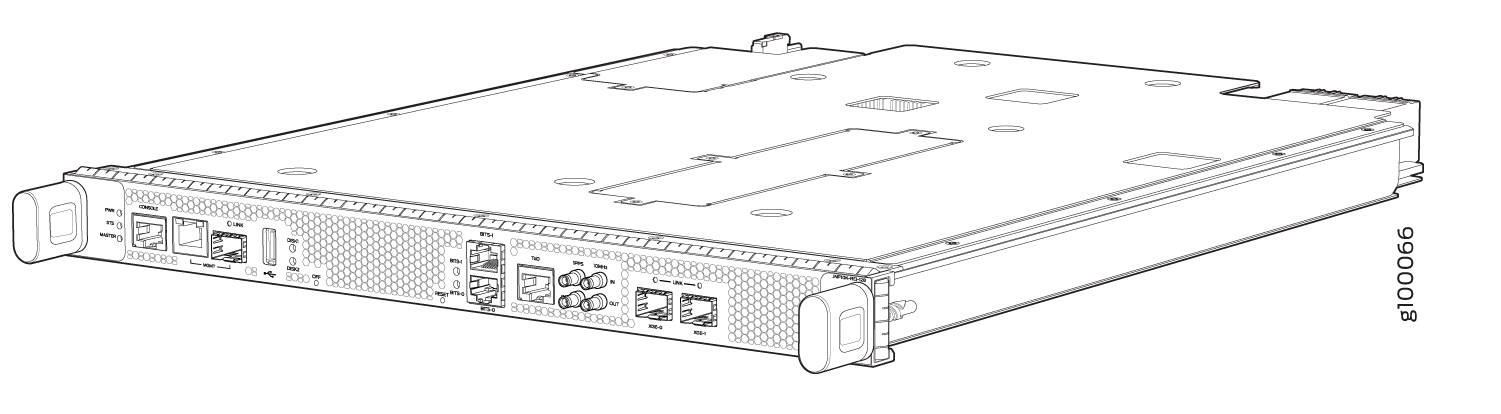
The Routing and Control Board (RCB) is an integrated board and a single field-replaceable unit (FRU) that provides Routing Engine and Control Board (CB) functionality. The Routing Engine performs all route-processing functions, whereas the CB performs chassis control and management plane functionality. The RCB provides control plane functions. You can install one or two RCBs on the router. Each RCB functions as a unit.
The MX10004 Routing and Control Board (RCB) is responsible for system management in an MX10004 router (see Figure 5 and Figure 2). The chassis can run with one or two RCBs. The base configuration ships with one RCB, while a redundant configuration ships with two RCBs. When two RCBs are installed, one functions as the primary and the second as a backup. If the primary RCB is removed, the backup becomes the primary if graceful Routing Engine switchover (GRES) is configured.
MX10004 supports the following Routing Engines:
-
JNP10K-RE3, 128 gigabytes of memory
-
JNP10K-RE3-LT, 128 gigabytes of memory
-
JNP10K-RE3-256, 256 gigabytes of memory
-
JNP10K-RE3LT256, 256 gigabytes of memory
-
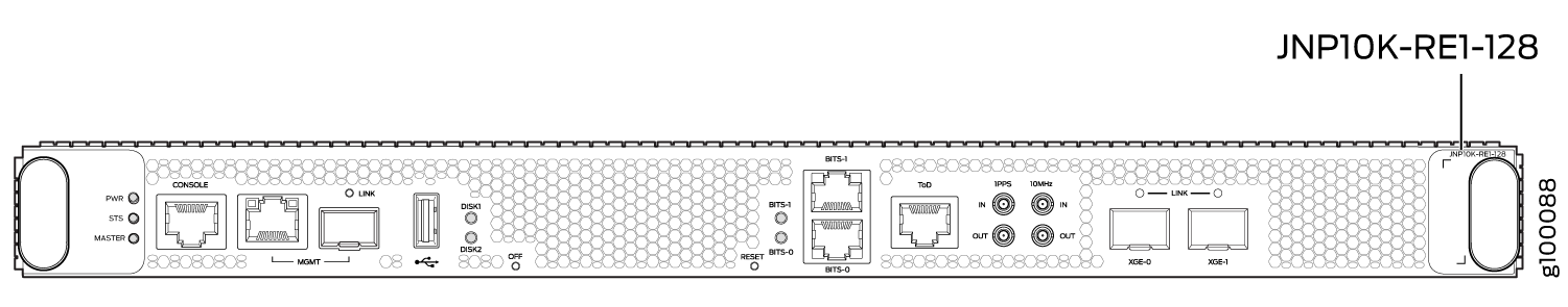
JNP10K-RE1
-
JNP10K-RE1-LT
-
JNP10K-RE1-128G
This topic covers:
Routing and Control Board Functions
The Routing and Control Board (RCB) integrates the control plane and Routing Engine functions into a single management unit. Each RCB provides all the functions needed to manage the operation of the modular chassis:
-
System control functions such as environmental monitoring
-
Routing Layer 2 and Layer 3 protocols
-
Communication to all components such as line cards, Switch Fabric Boards (SFBs), and power and cooling
-
Transparent clocking
-
Alarm and logging functions
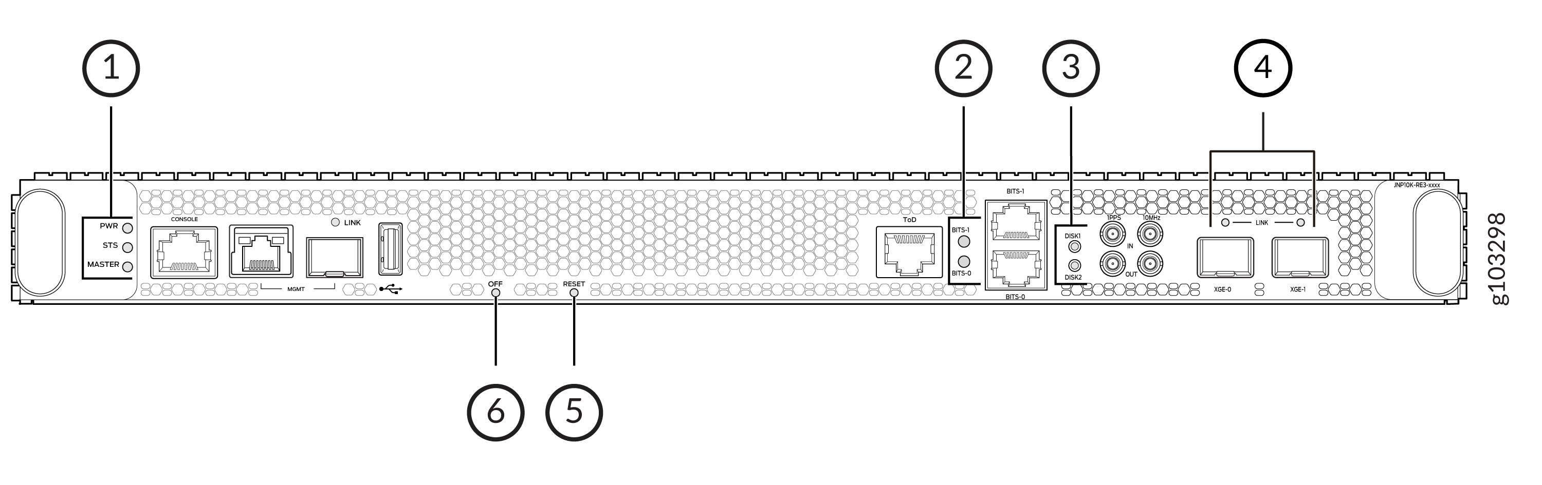
Routing and Control Board Components
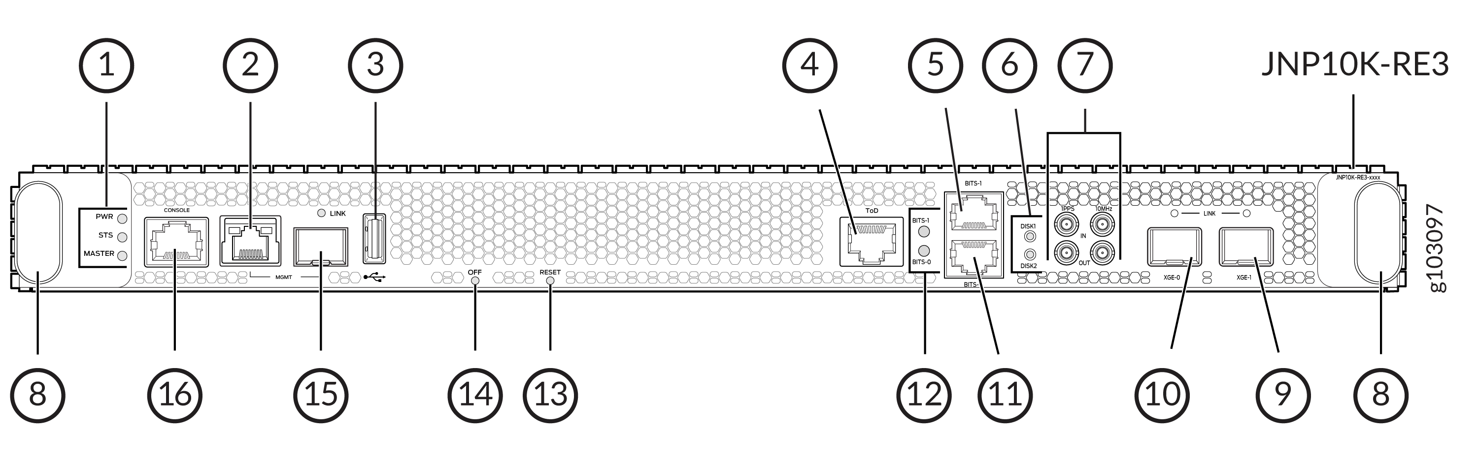
1 — RCB status LEDs | 9 — XGE-1 not used (reserved ports) |
2 — Management (MGMT) port | 10 — XGE-0 not used (reserved ports) |
3 — USB port | 11 — BITS0 clock port |
4 — ToD—Time-of-day (TOD) port | 12 — Clock LEDs |
5 — BITS1 clock port | 13 — Reset button |
6 — Solid State Disk (SSD) LEDs | 14 — Online/Offline button |
7 — GPS clock ports | 15 — Management (MGMT) port |
8 — Handles | 16 — Console (CONSOLE) port |
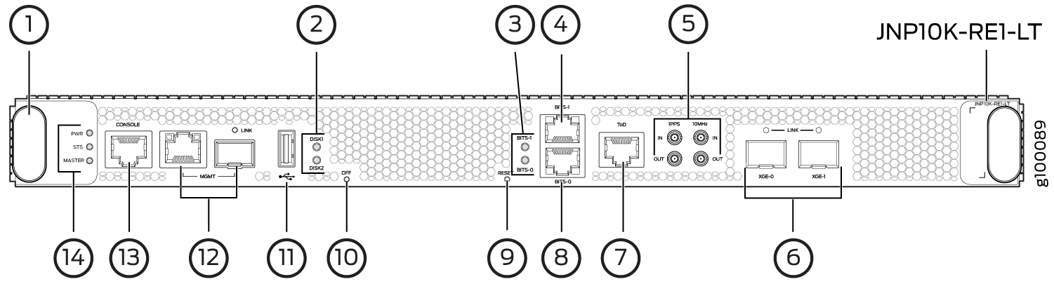
1 — Handles | 8 — BITS0 clock port |
2 — Solid State Disk (SSD) LEDs | 9 — Reset button |
3 — Clock LEDs | 10 — Online/Offline button |
4 — BITS1 clock port | 11 — USB port |
5 — GPS clock ports | 12 — Management (MGMT) ports |
6 — XGE-0 and XGE-1 not used (reserved ports) | 13 — Console (CONSOLE) port |
7 — ToD—Time-of-day (TOD) port | 14 — RCB status LEDs |
Each RCB consists of the following internal components:
-
CPU—Runs Junos OS to maintain the routing tables and routing protocols.
-
EEPROM—Stores the serial number of the Routing Engine.
-
DRAM—Provides storage for the routing and forwarding tables and for other Routing Engine processes.
-
One 10-Gigabit Ethernet interface between the Routing Engine and Switch Fabric Board.
-
One USB port—Provides a removable media interface through which you can install Junos OS manually. The Junos OS supports USB versions 3.0, 2.0, and 1.1.
-
Management ports—Two ports, one copper (RJ-45 port) and one SFP port, provide access to management devices. Use only one of the two management ports at a time.
Use an RJ-45 connector for the copper port.
Use a fiber optic connector for the SFP port.
Do not use copper SFP or SFP-T modules in the SFP port because they are not supported.
-
RESET button—When pressed, reboots the RCB as detailed below:
-
When pressed for fewer than 5 seconds for diagnostic purposes, the RCB does not reset. The press event is logged in the RCB FPGA register.
-
When pressed for more than 5 seconds but fewer than 10 seconds, the RCB reboots and the reset-reason logs the button press event.
-
When pressed for more than 10 seconds, the RCB reboots with an option for BIOS recovery.
-
-
LEDs—Provide status of the Routing Engine.
-
Online/Offline Button—When the RCB is online, and if the button is pressed for more than 4 seconds, the RCB goes offline. When the RCB is offline, and if the button is pressed more than 4 seconds, the RCB starts booting.
For specific information about Routing Engine components (for example, the
amount of DRAM), issue the show vmhost hardware
command.
MX10004 Routing and Control Board LEDs
The MX10004 Routing and Control Boards (RCBs) have various types of LED indicators. Figure 6 shows the LEDs on the Routing and Control Boards (JNP10K-RE1).
1 — RCB status panel LEDs | 4 — Link status LEDs for XGE-0 and XGE-1 ports |
2 — Clock LEDs–BITS-0, and BITS-1 | 5 — Reset button with LED |
3 — Solid State Disk (SSD) LEDs—DISK1 and DISK2 | 6 — On/Off button with LED |
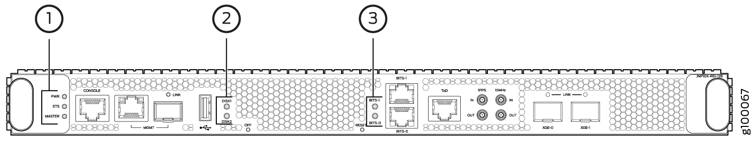
1 — RCB status panel LEDs | 3 — Clock LEDs–BITS-0, and BITS-1 |
2 — Solid State Disk (SSD) LEDs—DISK1 and DISK2 |
Routing and Control Board Status Panel LEDs
Table 1 describes the LEDs on the RCB status panel.
|
LED |
Color |
State |
Description |
|---|---|---|---|
|
PWR |
Green |
On steadily |
RCB is receiving adequate power. |
|
Yellow |
Blinking |
An error is detected in the RCB. |
|
|
Dark |
Unlit |
RCB is not powered up. |
|
|
STS |
Green |
On steadily |
RCB is online and functioning correctly. |
|
Green |
Blinking |
The beacon feature is enabled. |
|
|
Yellow |
On steadily |
The RCB is booting. |
|
|
Yellow |
Blinking |
An error has been detected in the RCB. |
|
|
Dark |
Unlit |
The power supply is switched off. |
|
|
MST |
Green |
On steadily |
The RCB is the primary. |
|
Dark |
Unlit |
The RCB is the backup. |
SATA SSD LEDs
The Serial Advanced Technology Attachment (SATA) solid-state drive (SSD) LEDs indicate the status of the secondary drive.
Table 2 describes the LEDs for the secondary SATA drives.
|
LED |
Color |
State |
Description |
|---|---|---|---|
|
DISK1 and DISK2 |
Green |
On steadily |
A SATA drive is present. |
|
Green |
Blinking |
The drive is active. |
|
|
Yellow |
On steadily |
The drive is active. |
|
|
Dark |
Unlit |
The drive is not installed. |
Clock LEDs
The clock LEDs indicate whether clocking is active.
Table 3 describes the clock LEDs.
|
LED |
Color |
State |
Description |
|---|---|---|---|
|
Clock LEDs—BITS-0 and BITS-1 |
Red |
Off |
Clock is active. |
|
On steadily |
Clock is not working. |
MX10004 Management Port LEDs
The two management ports on the RCB of an MX10004 router have LEDs that indicate link status and link activity. These two ports, located on the RCB panel between the clocking connections and the USB port, are both labeled MGMT. The left management port (RJ-45) is for 10/100/1000 BASE-T connections, and the right port (SFP) is for 10/100/1000 BASE-T and small form-factor pluggable (SFP) 1000 BASE-X connections (see Figure 7). The copper (RJ-45) port has separate LEDs for status and activity. The fiber (SFP) port has a combination link and activity LED.
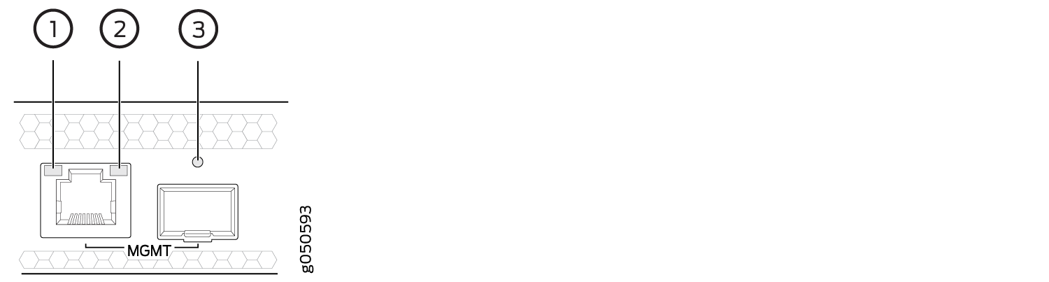
1 — Status LED (RJ-45) | 3 — Link/activity/status LED (SFP) |
2 — Activity LED (RJ-45) |
Table 4 describes the RJ-45 management port and SFP LEDs.
|
LED |
Color |
State |
Description |
|---|---|---|---|
|
Activity/Status LED |
Unlit |
Off |
The port speed is 10 MB. |
|
Green |
Blinking |
The port speed is 100 MB. |
|
|
Green |
On steadily |
The port speed is 1000 MB. |
|
|
LINK |
Unlit |
Off |
No link is established, there is a fault, or the link is down. |
|
Green |
On steadily |
A link is established. |
|
|
Blinking |
There is link activity. |
||
|
Yellow |
Blinking or flickering |
The beacon feature is enabled. |
Table 5 describes the SFP management port LEDs.
|
LED |
Color |
State |
Description |
|---|---|---|---|
|
Link/Activity/Status |
Unlit |
Off |
No transceiver is present. |
|
Green |
On steadily |
A link is established. The interface is up. |
|
|
Blinking or flickering |
The beacon feature is enabled. |
||
|
Yellow |
Blinking |
An error has occurred. |