ON THIS PAGE
MX10004 Power System
MX10004 routers support AC, DC, high-voltage alternating current (HVAC), and high-voltage direct current (HVDC) by offering the following power supplies:
-
JNP10K-PWR-AC3
-
JNP10K-PWR-AC2
-
JNP10K-PWR-DC3
-
JNP10K-PWR-DC2
-
JNP10K-PWR-AC3H
You can install up to three power supplies in the slots labeled PSU0 through PSU2 (top to bottom) located in the rear of the chassis.
The JNP10K-PWR-AC2 and JNP10K-PWR-AC3 can share power proportionally in a mixed configuration, only when you are upgrading to JNP10K-PWR-AC3.
The JNP10K-PWR-AC2 and JNP10K-PWR-AC3H can share power proportionally in a mixed configuration, provided all the four PSUs are powered either by HVAC or HVDC.
JNP10K-PWR-AC3 Power Supply
The JNP10K-PWR-AC3 power supply is a high-capacity model that is designed to support AC systems in a 15-A and 20-A mode; see Figure 1.
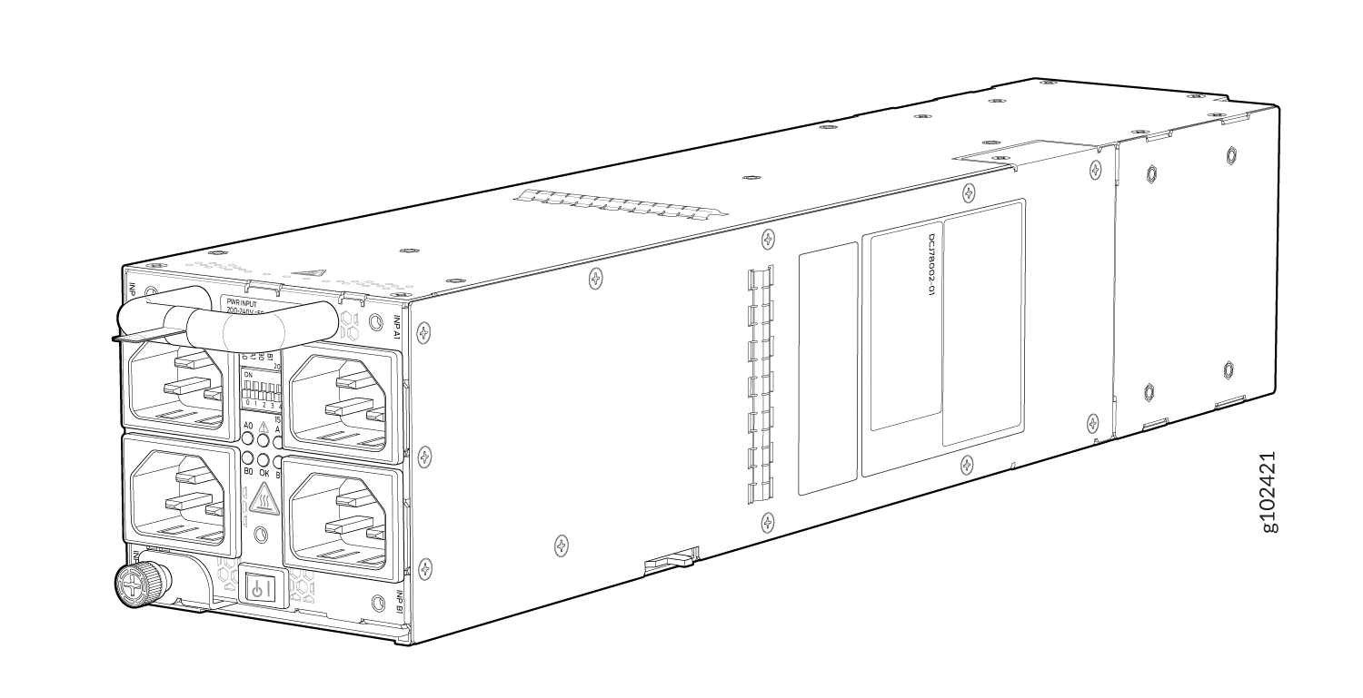
Input—The power supply takes four single-phase AC (180-264 VAC) inputs (A0, A1, B0, and B1) at either 20 A or 15 A and provides a DC output of 12.3V. The input receptacle on the AC power supply unit (PSU) is IEC 320-C22. The mating connector on the power cord is IEC 320-C21.
Output—The power supply provides DC output of 12.3V at:
- 7800 W (20-A input) with three or four active feeds, or
- 6000 W (20-A input) with two active feeds (either A0 and A1 or B0 and B1), or
- 3000 W (20-A input) with single active feed.
-
7800 W (15-A input) with four active feeds, or
-
6900 W (15-A input) with three active feeds, or
-
4600 W (15-A input) with two active feeds, or
-
2300 W (15-A input) with single active feed.
-
The operating input voltage range is 180 to 264 VAC for AC systems. The DC output is 12.3 VDC.
-
The number of power feeds and whether the power supplies provide high-output (20-A) or low-output (15-A) power are configured using a set of dual inline package (DIP) switches on the faceplate of the power supply. If one power supply in the chassis is set to low power, the power budget for the chassis is reduced to low power, regardless of their DIP switch settings or the output results in the CLI. This design safeguards against accidentally setting the power supply to 20 A in a facility that can provide only 15 A and tripping the facility circuit breaker. We recommend that you don’t mix DIP switch settings in your system. See Table 2 for information about the input and output voltages when you use the DIP switches.
-
The JNP10K-PWR-AC3 power supply has an ENABLE switch on the front panel to enable/disable the main 12.3 VDC output and +5.0 V_BIAS standby output as well. If the switch is in DISABLE position, the front-end PFC will be disabled to minimize power consumption. This switch has the highest priority over any other shutdown method.
-
The Power Factor Correction (PFC) is PF 0.98 kW minimum at full load. The maximum inrush current is 50 A for the active feed.
JNP10K-PWR-BLN3 or Active Blank
Juniper Networks offers an Active Blank Power Module (ABPM), JNP10K-PWR-BLN3. This helps in airflow and cooling in the chassis. You can have the following combination of ABPM, passive blank, and JNP10K-PWR-AC3 power supply units (PSU) in the router chassis:
-
Three PSUs
-
Two PSUs with one ABPM
-
One PSU with one ABPMs and one passive blank
-
One PSU with two ABPMs
-
Table 1: PSU, ABPM, Passive Blank Matrix JNP10K-PWR-AC3 PSU(s)
ABPM (JNP10K-PWR-BLN3)
Passive Blank
3
-
-
2
1
-
1
1
1
1
2
-
Note:A minimum of one JNP10K-PWR-AC3 power supply unit (PSU) must be present in the router chassis.
The JNP10K-PWR-AC3 power supply has internal fans that contribute to chassis cooling. Three PSUs or two PSUs along with a ABPM must be present in a running chassis to have the adequate airflow. While the minimum power supplies are required to be present in the chassis, they all need not be necessarily connected to power source. If a power supply is installed in a slot but not connected to a power source, it draws power from the chassis to power the internal fans in the power supplies.
Extreme burn danger—The JNP10K-PWR-AC3 can reach temperatures in the range of 158°F to 176°F (70°C to 80°C) under running conditions.
The router is pluggable type A equipment installed in a restricted-access location. It has a separate protective earthing terminal on the chassis that must be connected to earth ground permanently to ground the chassis adequately and protect the operator from electrical hazards.
Before you begin installing the router, ensure that a licensed electrician has attached an appropriate grounding lug to the grounding cable that you supply. Using a grounding cable with an incorrectly attached lug can damage the router.
Use a 2-pole circuit breaker rated at 25 A in the building installation and the system, or as per local electrical code.
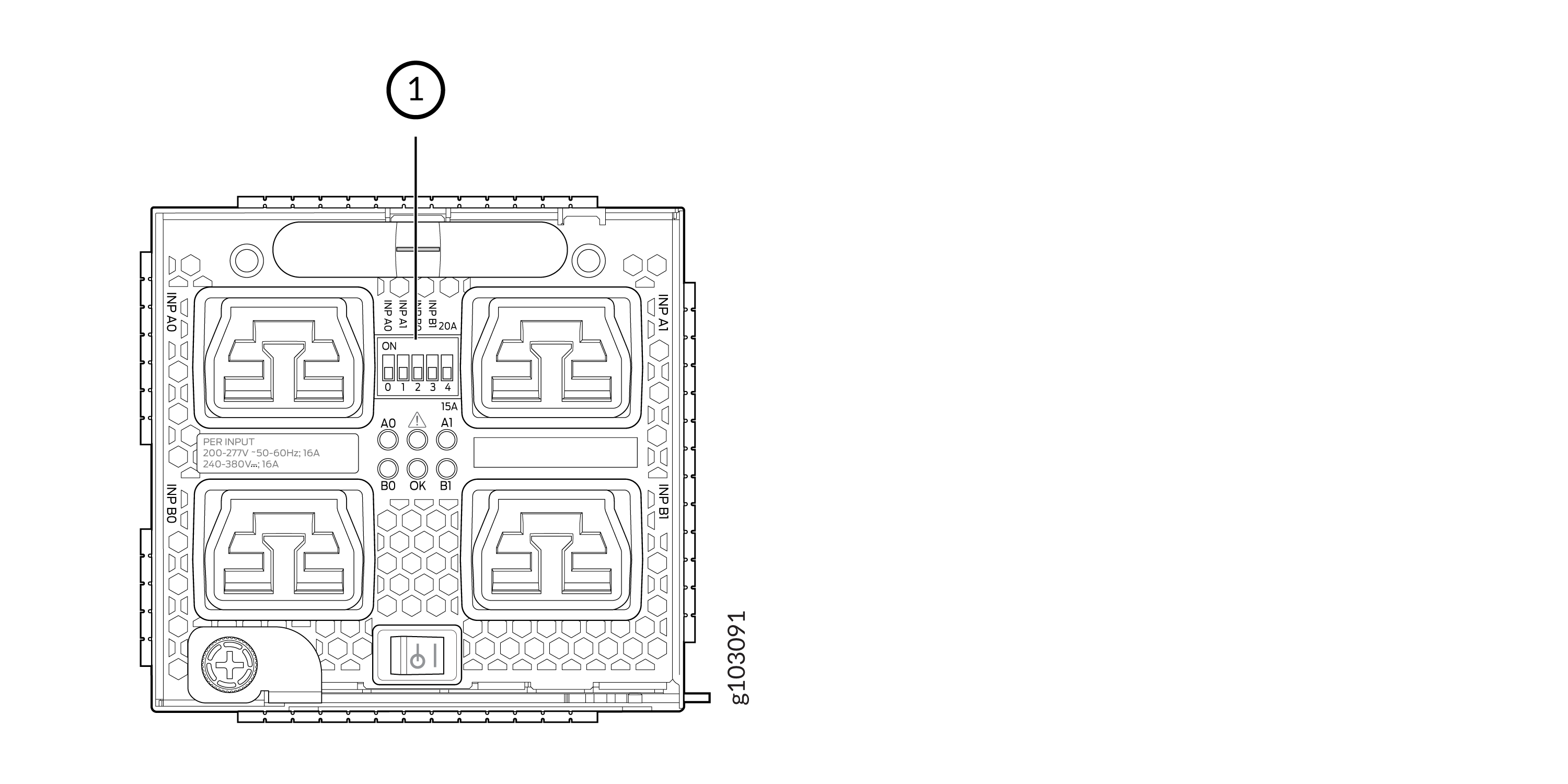
The JNP10K-PWR-AC3 Power Supplies have five dual position DIP switches (INP-A0, INP-A1, INP-B0, INP-B1, and DIP4) that are accessible from the front panel. DIP4 is the fifth DIP switch, which is used to indicate whether 20A or 15A input source is connected. See Figure 2 and Table 2 to know the layout of the DIP switches and the power output when the DIP switches are set in different combinations.
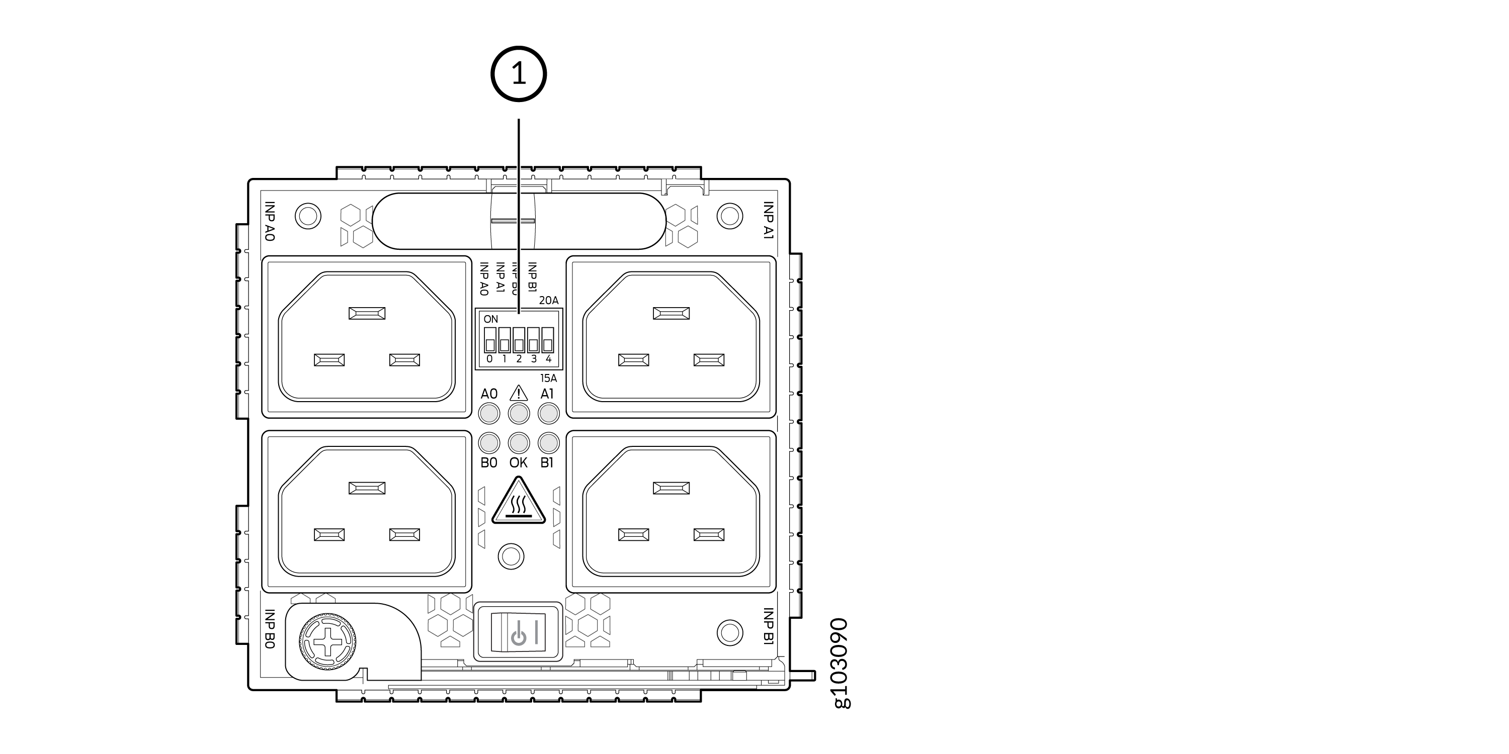
1—DIP switches
|
INP-A0 (Switch 0) |
INP-A1 (Switch 1) |
INP-B0 (Switch 2) |
INP-B1 (Switch 3) |
Switch 4 (High Input 20 A/Low Input 15 A) |
Output Power |
|---|---|---|---|---|---|
|
15-A |
|||||
|
Off |
Off |
Off |
On |
Off (15 A) |
2300 W |
|
Off |
Off |
On |
Off |
Off (15 A) |
2300 W |
|
Off |
Off |
On |
On |
Off (15 A) |
4600 W |
|
Off |
On |
Off |
Off |
Off (15 A) |
2300 W |
|
Off |
On |
Off |
On |
Off (15 A) |
4600 W |
|
Off |
On |
On |
On |
Off (15 A) |
6900 W |
|
Off |
On |
On |
Off |
Off (15 A) |
4600 W |
|
On |
Off |
Off |
Off |
Off (15 A) |
2300 W |
|
On |
Off |
Off |
On |
Off (15 A) |
4600 W |
|
On |
Off |
On |
Off |
Off (15 A) |
4600 W |
|
On |
Off |
On |
On |
Off (15 A) |
6900 W |
|
On |
On |
Off |
Off |
Off (15 A) |
4600 W |
|
On |
On |
Off |
On |
Off (15 A) |
6900 W |
|
On |
On |
On |
Off |
Off (15 A) |
6900 W |
|
On |
On |
On |
On |
Off (15 A) |
7800 W |
|
20-A |
|||||
|
Off |
Off |
Off |
On |
On (20 A) |
3000 W |
|
Off |
Off |
On |
Off |
On (20 A) |
3000 W |
|
Off |
Off |
On |
On |
On (20 A) |
6000 W |
|
Off |
On |
Off |
Off |
On (20 A) |
3000 W |
|
Off |
On |
Off |
On |
On (20 A) |
6000 W |
|
Off |
On |
On |
Off |
On (20 A) |
6000 W |
|
Off |
On |
On |
On |
On (20 A) |
7800 W |
|
On |
Off |
Off |
Off |
On (20 A) |
3000 W |
|
On |
Off |
Off |
On |
On (20 A) |
6000 W |
|
On |
Off |
On |
Off |
On (20 A) |
6000 W |
|
On |
Off |
On |
On |
On (20 A) |
7800 W |
|
On |
On |
Off |
Off |
On (20 A) |
6000 W |
|
On |
On |
Off |
On |
On (20 A) |
7800 W |
|
On |
On |
On |
Off |
On (20 A) |
7800 W |
|
On |
On |
On |
On |
On (20 A) |
7800 W |
It is important to connect the input feeds of the JNP10K-PWR-AC3 power supply to AC mains before powering-on the router.
JNP10K-PWR-AC3 Power Specifications
The JNP10K-PWR-AC3 power supply supports AC.
Table 3lists the power specifications for the AC power supply (JNP10K-PWR-AC3) used in a MX10004 chassis.
|
Specification |
Value |
|---|---|
|
AC input voltage |
180–264 VAC |
|
Input current rating |
16 A |
|
DC output power |
12.3 V |
Table 4 shows the physical specifications for a JNP10K-PWR-AC3 power supply.
|
Specification |
Value |
|---|---|
|
Height |
3.386 in. (8.60 cm) |
|
Width |
3.584 in. (9.10 cm) |
|
Depth |
17.15 in. (43.57 cm) |
|
Weight |
12.8 lbs (5.8 kg) |
JNP10K-PWR-AC3 Power Supply LEDs
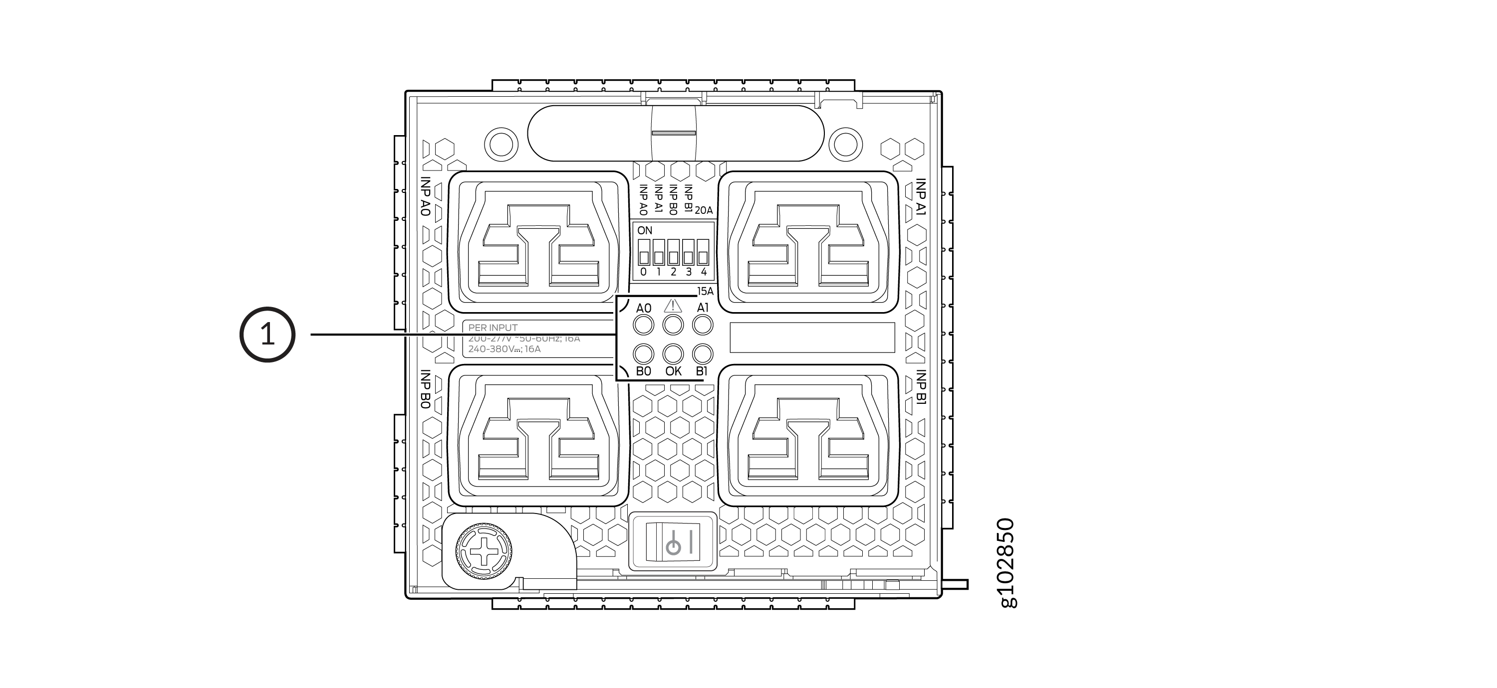
The JNP10K-PWR-AC3 power supply has six LEDs on its faceplate: !, OK, A0, A1, B0, and B1. The numbered LEDs correspond to the four inputs (INP-A0, INP-A1, INP-B0, and INP-B1). Additionally, there are two more LEDs OK (Power OK) and !(Fault). These LEDs display information about the status of the power supply. See Figure 3.
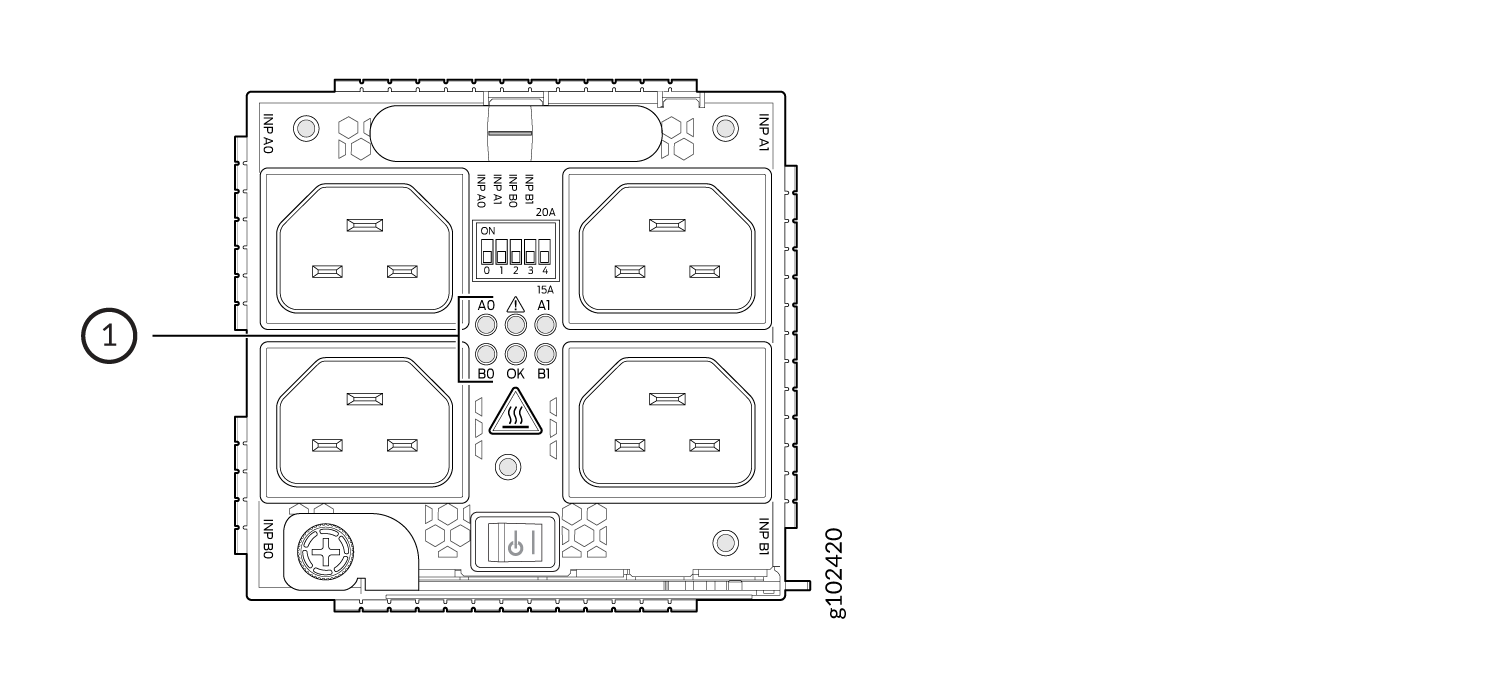
1—LEDs on the JNP10K-PWR-AC3 Power Supply denoting:
-
! Fault
-
OK Power OK
-
A0 INP A0–Source input 1
-
A1 INP A1–Source input 2
-
B0 INP B0–Source input 3
-
B1 INP B1–Source input 4
Physical markings on the power supply are INP-A0,
INP-A1, INP-B0, and
INP-B1. These markings correspond to INP-A0, INP-A1, INP-B0, and
INP-B1 in the show chassis power output (see Table 5).
|
Physical Marking on JNP10K-PWR-AC3 |
Corresponding Physical LED Marking |
show chassis power Command |
|---|---|---|
|
INP A0 |
A0 |
INP-A0 |
|
INP A1 |
A1 |
INP-A1 |
|
INP B0 |
B0 |
INP-B0 |
|
INP B1 |
B1 |
INP-B1 |
Table 6 describes the LEDs on a JNP10K-PWR-AC3 power supply, color on the LED, state, and its meaning.
|
LED |
Color |
State |
Description |
|---|---|---|---|
|
A0 |
Yellow |
Solid |
One of the following:
|
|
Green |
Solid |
The power supply is functioning properly. |
|
|
A1 |
Yellow |
Solid |
One of the following:
|
|
Green |
Solid |
The power supply is functioning properly. |
|
|
B0 |
Yellow |
Solid |
One of the following:
|
|
Green |
Solid |
The power supply is functioning properly. |
|
|
B1 |
Yellow |
Solid |
One of the following:
|
|
Green |
Solid |
The power supply is functioning properly. |
|
|
OK (Power OK) |
Green |
Solid |
The power supply is functioning properly. |
|
Yellow |
Blinking |
The power supply output has detected a fault. |
|
| Green | Blinking |
The power supply is functioning properly but there is a mismatch in the corresponding DIP switch. Example: If A0 is receiving input power but the corresponding DIP switch 0 is not ON, then the LED will blink green. |
|
|
Unlit |
Off |
The power supply is switched off. |
|
|
! (Fault) |
Red |
Solid |
The power supply has failed and must be replaced. |
|
Unlit |
Off |
The power supply is functioning normally. |
JNP10K-PWR-AC2 Power Supply
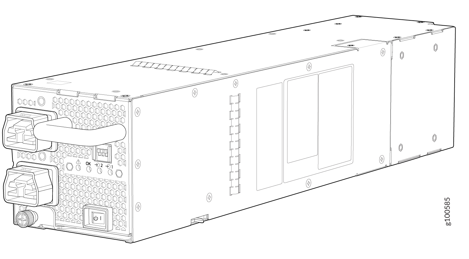
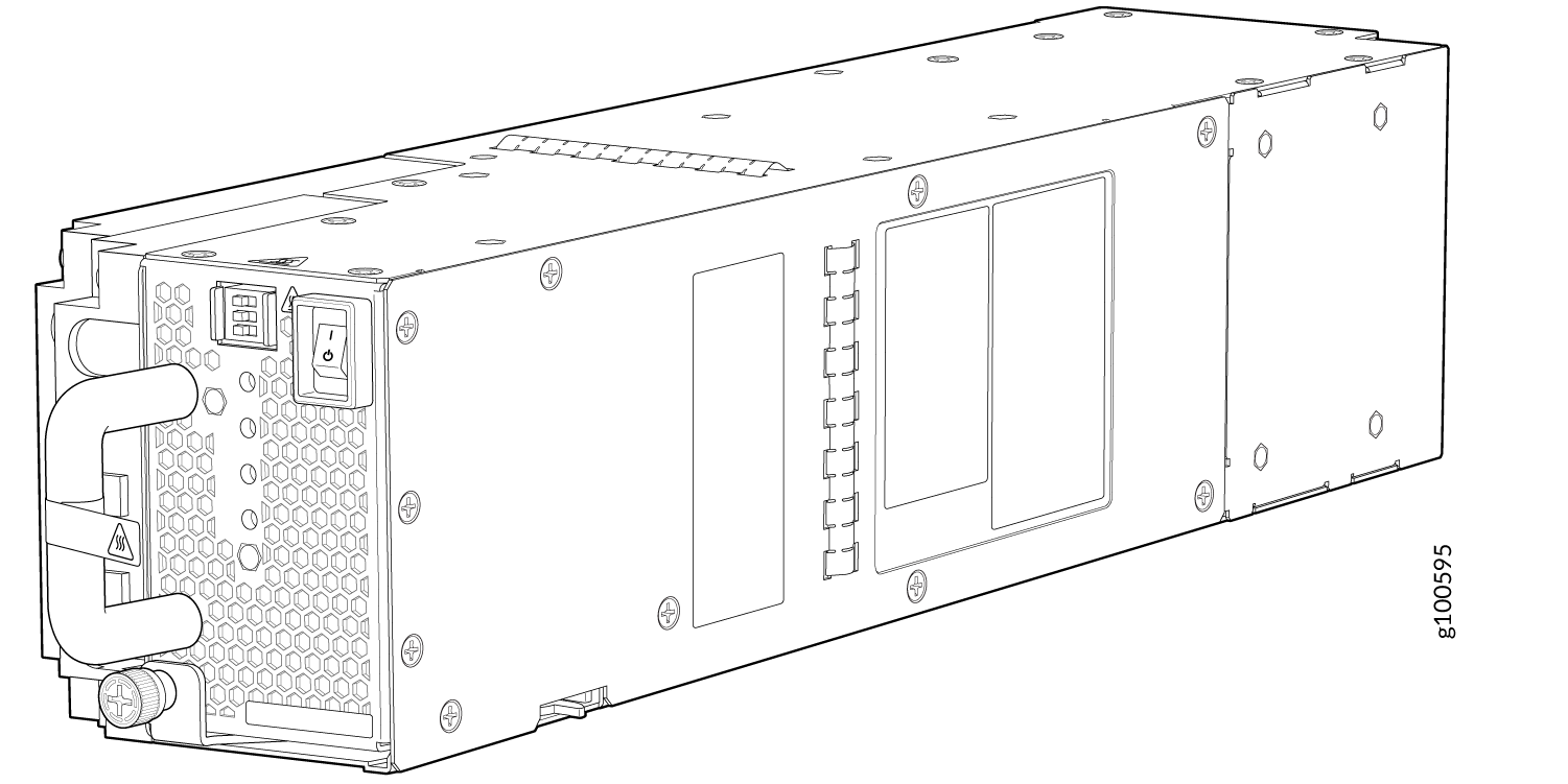
The JNP10K-PWR-AC2 power supply is a high-capacity model that is designed to support AC, high-voltage AC (HVAC), or high-voltage DC (HVDC) systems in either a 20-A or a 30-A mode; see Figure 4. The power supply feeds AC input and provides DC output of 5000 W with a single feed and 5500 W with a dual feed. The operating input voltage range is 180 to 305 VAC for AC systems and 190 to 410 VDC for DC systems.
You configure the number of power feeds and high or low output using a set of dual inline package (DIP) switches on the faceplate of the power supply. You use the switches to configure whether the power supplies provide high-output (30-A) or low-output (20-A) power. If one power supply in the chassis is set to low power, the power budget for the chassis is reduced to low power, regardless of the DIP switch settings or the output results in the CLI. This design safeguards against accidentally setting the power supply to 30 A in a facility that can provide only 20 A and tripping the facility circuit breaker. We recommend that you not mix DIP switch settings in your system. See Table 7 for information about the input and output voltages when you use the DIP switches.
The JNP10K-PWR-AC2 power supply has internal fans that contribute to chassis cooling. Consequently, all three power supplies must be present in a running chassis to provide adequate airflow. While all power supplies are required to be present in the chassis, they do not all need to be connected to power. If a power supply is installed in a slot but not connected to a power source, it draws power from the chassis to power the internal fans in the power supplies.
Extreme burn danger! Do not handle an HVAC or HVDC power supply running in the chassis without heat-protective gloves. The JNP10K-PWR-AC2 can reach temperatures in the range of 158° F to 176° F (70° C to 80° C) under running conditions.
The router is pluggable type A equipment installed in a restricted-access location. It has a separate protective earthing terminal on the chassis that must be connected to earth ground permanently to ground the chassis adequately and protect the operator from electrical hazards.
Before you begin installing the router, ensure that a licensed electrician has attached an appropriate grounding lug to the grounding cable that you supply. Using a grounding cable with an incorrectly attached lug can damage the router.
Use a 2-pole circuit breaker rated at 25 A in the building installation and the system, or according to the local electrical code.
|
INP0 (Switch 1) |
INP1 (Switch 2) |
H/L (High Input 30 A/Low Input 20 A) |
Output Power |
|---|---|---|---|
|
On |
On |
On (30 A) |
5500 W |
|
On |
On |
Off (20 A) |
3000 W |
|
On |
Off |
On (30 A) |
5000 W |
|
Off |
On |
On (30 A) |
5000 W |
|
On |
Off |
Off (20 A) |
2700 W |
|
Off |
On |
Off (20 A) |
2700 W |
It is important to connect both input feeds of the JNP10K-PWR-AC2 power supply to the main AC power before loading the system with power.
JNP10K-PWR-AC2 Power Specifications
The JNP10K-PWR-AC2 power supply supports AC, high-voltage alternating current (HVAC) and high-voltage direct current (HVDC).
Table 8 lists the power specifications for the AC power supply (JNP10K-PWR-AC2) used in an MX10004 chassis.
|
Specification |
Value |
|---|---|
|
AC input voltage |
180–305 VAC |
|
DC input voltage |
190–410 VDC |
|
Input current rating |
28.5 A |
|
DC output power |
12.3 V, 5500 W with dual feed and 5000 W with single feed |
Table 9 shows the physical specifications for a JNP10K-PWR-AC2 power supply.
|
Specification |
Value |
|---|---|
|
Height |
3.5 in. (8.89 cm) |
|
Width |
3.6 in. (9.14 cm) |
|
Depth |
15.1 in. (38.35 cm) |
|
Weight |
11.4 lb (5.17 kg) |
JNP10K-PWR-AC2 Power Supply LEDs
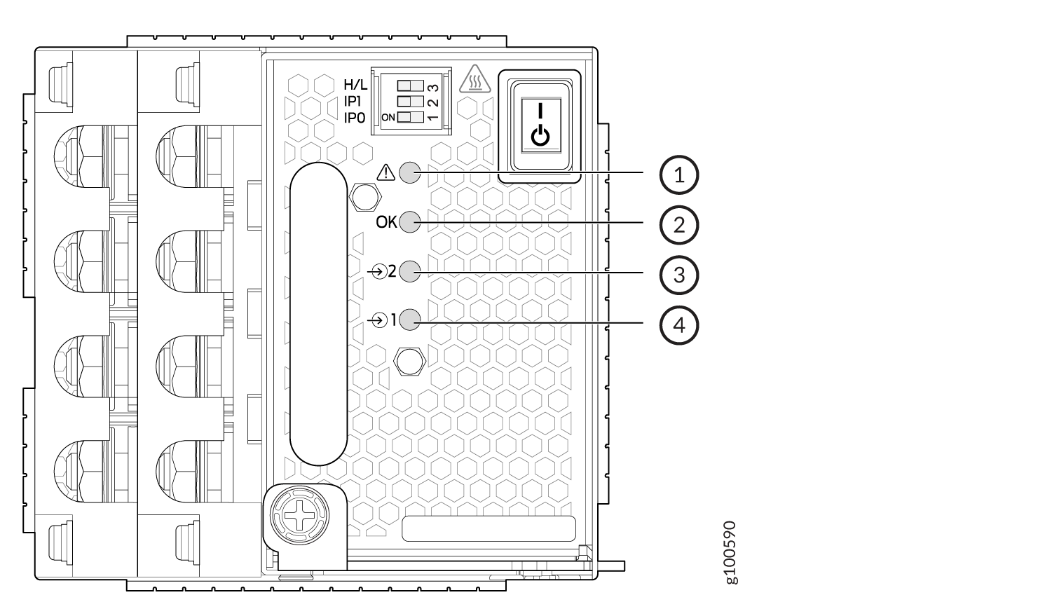
The JNP10K-PWR-AC2 power supply has four LEDs on its faceplate: !, OK, 2, and 1. These LEDs display information about the status of the power supply. See Figure 5.
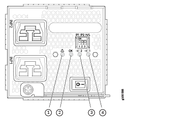
1 — ! Fault | 3 — 2 INP2–Source input 2 |
2 — OK Power OK | 4 — 1 INP1–Source input 1 |
Physical markings on the power supply are 1 and
2. These markings correspond to INP1 and INP2 in the show
chassis power output (see Table 10).
You can display the DIP switch settings for input and output power using the show
chassis power command.
|
Physical Marking on JNP10K-PWR-AC2 |
show chassis power Command |
|---|---|
|
INP1 |
INP1 |
|
INP2 |
INP2 |
Table 11 describes the LEDs on a JNP10K-PWR-AC2 power supply.
|
LED |
Color |
State |
Description |
|---|---|---|---|
|
1 or ( |
Yellow |
Solid |
The power supply is switched on while the power connector for source input 1 (INP1) is unplugged. |
|
Blinking |
The input voltage is present, but a fault is detected. |
||
|
Green |
Solid |
The power supply is functioning properly. |
|
|
Unlit |
Off |
The power supply is switched off; voltage is zero. |
|
|
2 or ( |
Yellow |
Solid |
The power supply is switched on while the power connector for source input 2 (INP2) is unplugged. |
|
Blinking |
The input voltage is present, but a fault is detected. |
||
|
Green |
Solid |
The power supply is functioning properly. |
|
|
Unlit |
Off |
The power supply is switched off; voltage is zero. |
|
|
OK (Power OK) |
Green |
Solid |
The power supply is functioning properly. |
|
Yellow |
Blinking |
The power supply output has detected a fault. |
|
|
Unlit |
Off |
The power supply is switched off. |
|
|
! (Fault) |
Red |
Solid |
The power supply has failed and must be replaced. |
|
Unlit |
Off |
The power supply is functioning normally. |
MX10004 Power Cable Specifications
Most sites distribute power through a main conduit that leads to frame-mounted power distribution panels, one of which can be located at the top of the rack that houses the router. An AC power cord connects each power supply to the power distribution panel.
In North America, AC power cords must not exceed 15 feet (approximately 4.5 meters) in length, to comply with National Electrical Code (NEC) Sections 400-8 (NFPA 75, 5-2.2) and 210-52 and with Canadian Electrical Code (CEC) Section 4-010(3). The cords shipped with the router to North America and Canada are in compliance.
The MX10004 AC, high-voltage alternating current (HVAC), and high-voltage direct current (HVDC) power supplies have specific cord requirements. Use the following sections to determine the cable requirements based on the model of your power supply and any mode settings:
-
For JNP10K-PWR-AC3 with 20-A input and 15-A input, see JNP10K-PWR-AC3 Power Cable Specifications.
-
For JNP10K-PWR-AC2 with 20-A input, see JNP10K-PWR-AC2 Power Cable Specifications.
-
For JNP10K-PWR-AC2 with 30-A input, see JNP10K-PWR-AC2 Power Cable Specifications for 30-A Input.
- JNP10K-PWR-AC3 Power Cable Specifications
- JNP10K-PWR-AC2 Power Cable Specifications
- JNP10K-PWR-AC2 Power Cable Specifications for 30-A Input
JNP10K-PWR-AC3 Power Cable Specifications
The JNP10K-PWR-AC3 power supply operates in two modes:
-
20-A input with 7800 W or 6000 W or 3000 W output
-
15-A input with 7800 W or 7500 W, or 5000 W, or 2500 W output
When power cords with right angle plugs at the PSU end are selected, they must be in pairs of Right Angle Left Plugs for inputs A0 or B0 and Extended Right Angle Left Plugs for inputs A1 or B1.
See Table 12 for a list of appropriate cables.
Do not run JNP10K-PWR-AC3 power supplies using 16-A or 20-A cables if connected to 15-A input.
You can prevent AC power cables from being exposed to hot air exhaust by always routing the power cables away from the fan trays and power supplies.
With right angle power cords and the baffle installed, the power cords will be exposed to hot exhaust air. The IEC C21 plugs have a temperature rating of 155C and the power cord cables have a rating of 90C.
|
Locale |
Cord Set Rating |
Plug Standard |
Spare Juniper Model Number |
Graphic |
|---|---|---|---|---|
| Straight Plug at PSU Input | ||||
|
Australia and New Zealand |
15 A, 250 VAC | AS/NZS 3112 |
CBL-PWRC21-AU |
|
|
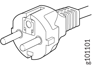
Europe (except Italy, Switzerland, and United Kingdom) |
16A, 250 VAC | CEE 7/7 |
CBL-PWRC21-EU |
 |
|
Italy |
16A, 250 VAC | CEI 23-16 |
CBL-PWRC21-IT |
|
|
North America |
20A, 250 VAC |
Locking NEMA L6-20P |
CBL-PWRC21-US-L |
|
| NEMA 6-20P |
CBL-PWRC21-US |
|
||
| International | 16A, 250VAC |
IEC-309 316P6W |
CBL-PWRC21-316P6 |
|
| North America | 20A, 250 VAC |
IEC-309 320P6W |
CBL-PWRC21-320P6 |
|
| Japan | 20A, 250 VAC | NEMA L6-20P |
CBL-PWRC21-JP-L |
|
| China | 16A, 250 VAC | GB2099-1 |
CBL-PWRC21-CN |
|
| North America | 20A, 250 VAC | IEC-320-C20 |
CBL-PWRC21-C20-NA |

|
| Europe | 16A, 250 VAC | IEC-320-C20 |
CBL-PWRC21-C20-EU |
|
| Japan | 20A, 250 VAC | IEC-320-C20 |
CBL-PWRC21-C20-JP |
|
| China | 16A, 250 VAC | IEC-320-C20 |
CBL-PWRC21-C20-CN |
|
| Switzerland | 16A, 250 VAC | SEV1011 |
CBL-PWRC21-SZ |
|
| South Africa | 16A, 250 VAC |
RA SANs 164/1 |
CBL-PWRC21-SA |
|
| India | 16A, 250VAC | RA IS 1293 |
CBL-PWRC21-IN |
|
| United Kingdom | 16A, 250 VAC | BS 1363 |
CBL-PWRC21-UK |
 |
| Israel | 16A, 250 VAC |
SI 32/1971 Type IL/3G |
CBL-PWRC21-IL |
|
| Brazil | 16A, 250 VAC |
NBR 14136 Type BR/3 |
CBL-PWRC21-BR |
|
| Argentina | 16A, 250 VAC |
IRAM 2073 Type RA/3 |
CBL-PWRC21-AR |
|
| Right Angle Left Plug at PSU Input | ||||
| USA | 20A, 250 VAC | NEMA L6-20P | CBL-PWRC21R-US-L |
|
| USA | 20A, 250 VAC | NEMA 6-20P | CBL-PWRC21R-US |
|
| Europe | 16A, 250 VAC | CEE 7/7 | CBL-PWRC21R-EU |
|
| Australia | 15A, 250 VAC | AS/NZ 3112 | CBL-PWRC21R-AU |
|
| Italy | 16A, 250 VAC | CEI 23-50 | CBL-PWRC21R-IT |
|
| International | 16A, 250 VAC |
IEC 60309 316P6W |
CBL-PWRC21R-316P6 | |
| North America | 16A, 250VAC |
IEC 60309 320P6W |
CBL-PWRC21R-320P6 | |
| Japan | 20A, 250 VAC | NEMA L6-20P | CBL-PWRC21R-JP-L |
|
| China | 16A, 250 VAC | GB2099-1 | CBL-PWRC21R-CN |
|
| North America | 16A, 250 VAC |
IEC-60320 C20 |
CBL-PWRC21R-C20-NA |
|
| Europe | 16A, 250 VAC |
IEC 60320 C20 |
CBL-PWRC21R-C20-EU |
|
| Japan | 20A, 250 VAC |
IEC 60320 C20 |
CBL-PWRC21R-C20-JP |
|
| China | 16A, 250 VAC |
IEC 60320 C20 |
CBL-PWRC21R-C20-CN |
|
| Switzerland | 16A, 250 VAC | SEV 1011 | CBL-PWRC21R-SZ | |
| South Africa | 16A, 250 VAC | SANS 164/1 | CBL-PWRC21R-SA |
|
| India | 16A, 250 VAC | IS 1293, RA | CBL-PWRC21R-IN |
|
| United Kingdom | 16A, 250 VAC | BS1363 | CBL-PWRC21R-UK | |
| Israel | 16A, 250 VAC |
SI 32/1971 TYPE IL/3G |
CBL-PWRC21R-IL |
|
| Brazil | 16A, 250 VAC |
NBR 14136 TYP BR/3 |
CBL-PWRC21R-BR |
|
| Argentina | 16A, 250 VAC |
IRAM 2073 TYPE RA/3 |
CBL-PWRC21R-AR |
|
| Extended Right Angle Left Plug at PSU Input | ||||
| USA | 20A, 250 VAC | NEMA L6-20P | CBL-PWRC21RL-US-L |
|
| USA | 20 A, 250 VAC | NEMA 6-20P | CBL-PWRC21RL-US |
|
| Europe | 16A, 250 VAC | CEE 7/7 | CBL-PWRC21RL-EU |
|
| Australia | 15A, 250 VAC | AS/NZ 3112 | CBL-PWRC21RL-AU |
|
| Italy | 16A, 250 VAC | CEI 23-50 | CBL-PWRC21RL-IT |
|
| International | 16A, 250 VAC |
IEC-60309 316P6W |
CBL-PWRC21RL-316P6 | |
| North America | 20A, 250 VAC |
IEC-60309 320P6W |
CBL-PWRC21RL-320P6 | |
| Japan | 20A, 250 VAC | NEMA L6-20P | CBL-PWRC21RL-JP-L |
|
| China | 16A, 250 VAC | GB2099-1 | CBL-PWRC21RL-CN |
|
| North America | 20A, 250 VAC |
IEC-60320 C20 |
CBL-PWRC21RL-C20NA |
|
| Europe | 16A, 250 VAC |
IEC-60320 C20 |
CBL-PWRC21RL-C20EU |
|
| Japan | 20A, 250 VAC |
ICE-60320 C20 |
CBL-PWRC21RL-C20JP |
|
| China | 16A, 250 VAC |
IEC-60320 C20 |
CBL-PWRC21RL-C20CN |
|
| Switzerland | 16A, 250 VAC | SEV 1011 | CBL-PWRC21RL-SZ | |
| South Africa | 16A, 250 VAC | SANS 164/1 | CBL-PWRC21RL-SA |
|
| India | 16A, 250 VAC | IS1293, RA | CBL-PWRC21RL-IN |
|
| United Kingdom | 16A, 250 VAC | BS 1363 | CBL-PWRC21RL-UK | |
| Israel | 16A, 250 VAC |
SI 32/1971 Type IL/3G |
CBL-PWRC21RL-IL |
|
| Brazil | 16A, 250 VAC |
NBR 14136 Type BR/3 |
CBL-PWRC21RL-BR |
|
| Argentina | 16A, 250 VAC |
IRAM 2073 Type RA/3 |
CBL-PWRC21RL-AR |
|
JNP10K-PWR-AC2 Power Cable Specifications
The JNP10K-PWR-AC2 power supply operates in two modes:
-
20-A input with 3000-W output; see Table 13 for a list of appropriate cables.
-
30-A input with 5500-W output; see JNP10K-PWR-AC2 Power Cable Specifications for 30-A Input for a list of appropriate cables and connectors for 30-A input.
Do not run JNP10K-PWR-AC2 power supplies using 16-A or 20-A cables if connected to 30-A input.
You can prevent AC power cables from being exposed to hot air exhaust by always routing the power cables away from the fan trays and power supplies.
|
Locale |
Cord Set Rating |
Plug Standard |
Spare Juniper Model Number |
Graphic |
|---|---|---|---|---|
|
Argentina |
16 A, 250 VAC |
IRAM 2073 Type RA/3 |
CBL-JNP-SG4-AR |
|
|
Australia and New Zealand |
15 A, 250 VAC |
AS/NZS 3112 |
CBL-JNP-SG4-AU |
|
|
Brazil |
16 A, 250 VAC |
NBR 14136 Type BR/3 |
CBL-JNP-SG4-BR |
|
|
China |
16 A, 250 VAC |
GB2099 |
CBL-JNP-SG4-CH |
|
|
Europe (except Italy, Switzerland, and the United Kingdom) |
20 A, 250 VAC |
CEE 7/7 |
CBL-JNP-SG4-EU |
|
|
Great Britain |
13 A, 250 VAC |
BS1363 |
CBL-JNP-SG4-UK |
|
|
India |
16 A, 250 VAC |
SANS 164/1 |
CBL-JNP-SG4-SA |
|
|
Israel |
16 A, RA, 250 VAC |
SI 32/1971 Type IL/3C |
CBL-JNP-SG4-IL |
|
|
Italy |
16 A, 250 VAC |
CEI 23-16 |
CBL-JNP-SG4-IT |
|
|
North America |
20 A, 250 VAC |
3-5958P4 to IEC 60320 C20 |
CBL-JNP-SG4-C20 |
|
|
16 A, 250 VAC |
Locking NEMA L6-20P |
CBL-JNP-SG4-US-L |
|
|
|
NEMA 6-20P |
CBL-JNP-SG4-US |
|
||
|
15 A, 277 V |
NEMA I7-20P |
CBL-JNP-SG4-HVAC |
|
|
|
South Africa |
16 A, 250 VAC |
SANS 164/1 |
CBL-JNP-SG4-SA |
|
|
Switzerland |
16 A, 250 VAC |
CEI 23-50 |
CBL-JNP-SG4-SZ |
|
JNP10K-PWR-AC2 Power Cable Specifications for 30-A Input
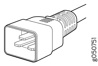
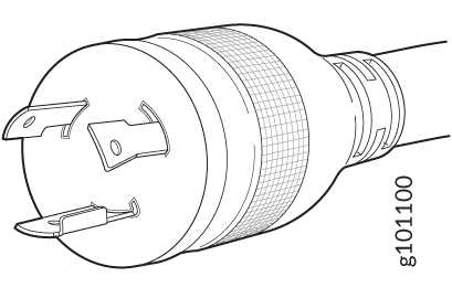
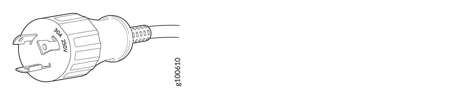
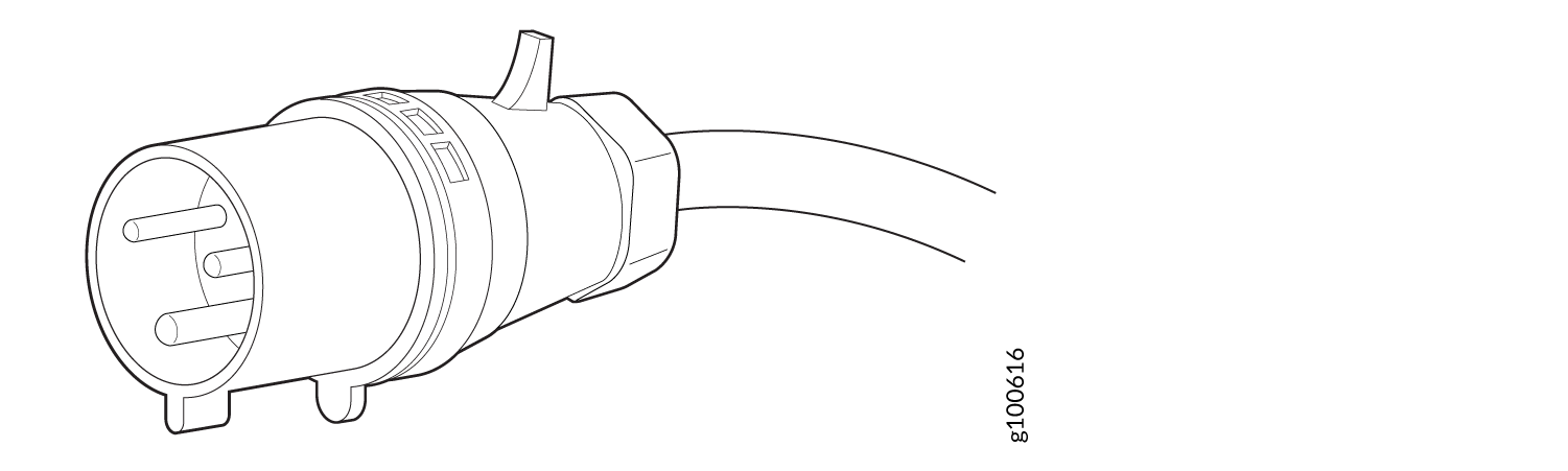
The JNP10K-PWR-AC2 HVAC or HVDC power supplies require a high-current cable assembly when set for 30-A input. One end of the cable has an Anderson APP-400 connector, while the other end of the cable is bare wire. See Figure 6 and Table 14. These cables are separately orderable and are not shipped automatically with JNP10K-PWR-AC2 orders. An example of the right-angle cable and connector is shown in Figure 8.
For connection to AC systems, Juniper Networks provides a cable with either a NEMA 30-A connector (Figure 6) or an IEC 330P6W connector (Figure 7).
|
Option |
Locale |
Cord Set Rating |
Plug Standards |
Connector |
Spare Juniper Model Number |
|---|---|---|---|---|---|
|
HVAC/HVDC power cord |
Any |
30 A 400 VAC |
UL 950 and IEC 60950 |
Anderson/straight to bare wire |
CBL-PWR2-BARE |
|
Any |
30 A 400 VAC |
UL 950 and IEC 60950 |
Anderson/right-angle to bare wire |
CBL-PWR2-BARE-RA |
|
|
AC power cord |
Continental Europe |
30 A 250 VAC |
UL 950 and IEC332P6 |
Anderson/right-angle to IEC 332P6 |
CBL-PWR2-332P6W-RA |
|
Continental Europe |
30 A 250 VAC |
UL 950 and IEC332P6 |
Anderson/straight to IEC332P6 |
CBL-PWR2-332P6W |
|
|
Continental Europe |
30 A 240 VAC |
IEC330P6 |
Anderson/right-angle to IEC 330P6 |
CBL-PWR2-330P6W-RA |
|
|
Continental Europe |
30 A 240 VAC |
IEC330P6 |
Anderson/straight to IEC 330P6 |
CBL-PWR2-330P6W |
|
|
North America |
30 A 250 VAC |
UL 498 and CSA |
Anderson/right-angle to L6-30P (NEMA-30A) |
CBL-PWR2-L6-30P-RA |
|
|
North America |
30 A 250 VAC |
UL 498 and IEC5958P4 |
Anderson/straight to L6-30P (NEMA-30A) |
CBL-PWR2-L6-30P |
|
|
AC jumper power cord |
Any |
30 A 400 VAC |
UL and CSA |
Anderson/straight to Anderson |
CG-CBL-APP-400-02 |
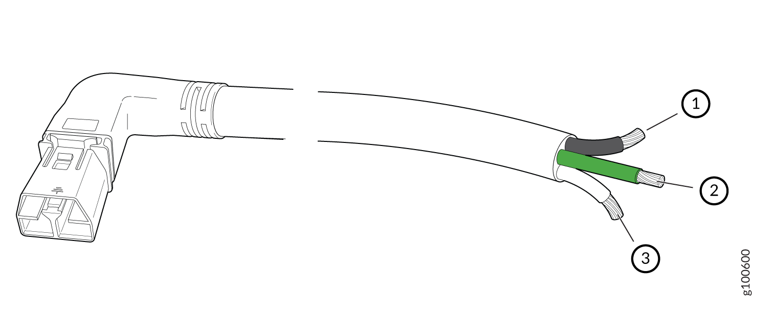
1 — Black wire –“+” or “-” for HVDC and “Hot or neutral” for AC | 3 — White wire – “+” or “-” for HVDC and “Hot or neutral” for AC |
2 — Green wire - Ground |
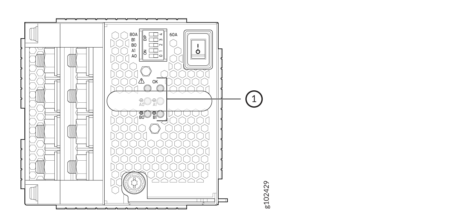
JNP10K-PWR-DC3 Power Supply
The JNP10K-PWR-DC3 power supply is a high-capacity model designed to support four power supplies in a single housing that accepts either 60 A or 80 A from four input power feeds.
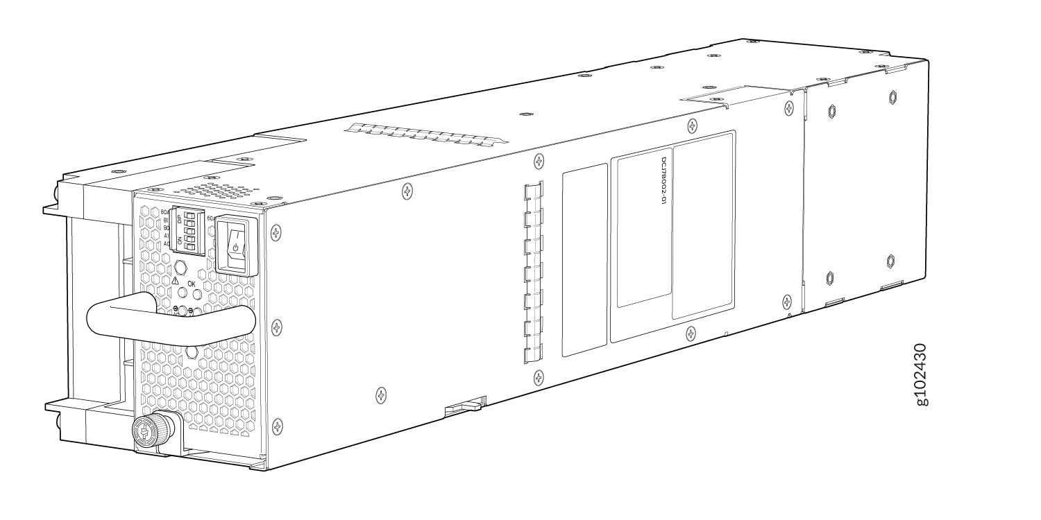
The JNP10K-PWR-DC3 power supply has an ON/Standby switch on the front panel to enable or disable the main 12.3 VDC output and +5.0 V_BIAS standby output.
The number of power feeds and whether the power supplies provide high input of 80 A or low input of 60 A are configured using the dual inline package (DIP) switches on the front panel of the power supply. The JNP10K-PWR-DC3 power supplies have five dual-position DIP switches. DIP0 through DIP3 switches (INP-A0, INP-A1, INP-B0, INP-B1) indicates whether the input is connected to the source. DIP4 (fifth DIP switch) indicate whether an 80 A or 60 A input source is connected. See Figure 10 for the layout of the DIP switches, and Table 15 for information on the power output when the DIP switches are set in different combinations.
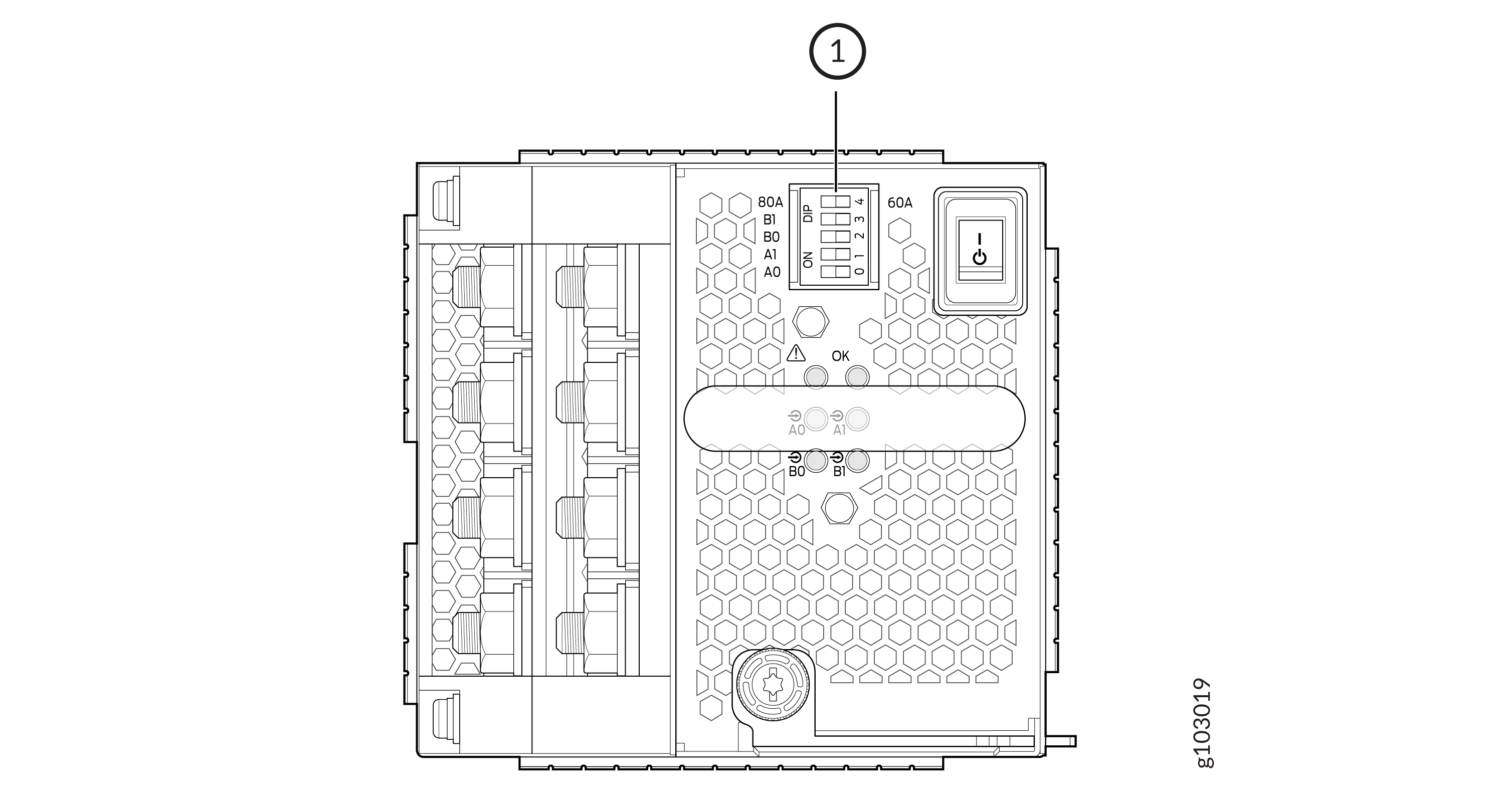
1 — DIP Switches |
|
INP-A0 (Switch 0) |
INP-A1 (Switch 1) |
INP-B0 (Switch 2) |
INP-B1 (Switch 3) |
Switch 4 (Low Input 60 A/ High Input 80 A) |
Output Power |
|---|---|---|---|---|---|
|
60 A |
|||||
|
Off |
Off |
Off |
On |
Off (60 A) |
2200 W |
|
Off |
Off |
On |
Off |
Off (60 A) |
2200 W |
|
Off |
Off |
On |
On |
Off (60 A) |
4400 W |
|
Off |
On |
Off |
Off |
Off (60 A) |
2200 W |
|
Off |
On |
Off |
On |
Off (60 A) |
4400 W |
|
Off |
On |
On |
Off |
Off (60 A) |
4400 W |
|
Off |
On |
On |
On |
Off (60 A) |
6600 W |
|
On |
Off |
Off |
Off |
Off (60 A) |
2200 W |
|
On |
Off |
Off |
On |
Off (60 A) |
4400 W |
|
On |
Off |
On |
Off |
Off (60 A) |
4400 W |
|
On |
Off |
On |
On |
Off (60 A) |
6600 W |
|
On |
On |
Off |
Off |
Off (60 A) |
4400 W |
|
On |
On |
Off |
On |
Off (60 A) |
6600 W |
|
On |
On |
On |
Off |
Off (60 A) |
6600 W |
|
On |
On |
On |
On |
Off (60 A) |
7800 W |
|
80 A |
|||||
|
Off |
Off |
Off |
On |
On (80 A) |
3000 W |
|
Off |
Off |
On |
Off |
On (80 A) |
3000 W |
|
Off |
Off |
On |
On |
On (80 A) |
6000 W |
|
Off |
On |
Off |
Off |
On (80 A) |
3000 W |
|
Off |
On |
Off |
On |
On (80 A) |
6000 W |
|
Off |
On |
On |
Off |
On (80 A) |
6000 W |
|
Off |
On |
On |
On |
On (80 A) |
7800 W |
|
On |
Off |
Off |
Off |
On (80 A) |
3000 W |
|
On |
Off |
Off |
On |
On (80 A) |
6000 W |
|
On |
Off |
On |
Off |
On (80 A) |
6000 W |
|
On |
Off |
On |
On |
On (80 A) |
7800 W |
|
On |
On |
Off |
Off |
On (80 A) |
6000 W |
|
On |
On |
Off |
On |
On (80 A) |
7800 W |
|
On |
On |
On |
Off |
On (80 A) |
7800 W |
|
On |
On |
On |
On |
On (80 A) |
7800 W |
Active Blank (JNP10K-PWR-BLN3)
Juniper Networks offers the JNP10K-PWR-BLN3, which is an Active Blank Power Module (ABPM). This helps in airflow and cooling in the chassis in the absence of a power supply unit (PSU). You can configure the router chassis with a combination of ABPM and JNP10K-PWR-DC3 PSUs:
|
JNP10K-PWR-DC3 PSU(s) |
JNP10K-PWR-BLN3 ABPM |
|---|---|
|
3 |
- |
|
2 |
1 |
|
1 |
2 |
A minimum of one JNP10K-PWR-DC3 PSU must be present in the router chassis.
The JNP10K-PWR-DC3 power supply has internal fans that contribute to chassis cooling. Three PSUs or two PSUs along with an ABPM must be present in a running chassis to have the adequate airflow. Minimum power supplies must be present in the chassis but all of them need not be connected to power source. If a power supply is installed in a slot but not connected to a power source, it draws power from the chassis to power the internal fans in the power supplies.
The router is pluggable type A equipment installed in a restricted-access location. It has a separate protective earthing terminal on the chassis that must be connected to earth ground permanently to ground the chassis adequately and protect the operator from electrical hazards.
Before you begin installing the router, ensure that a licensed electrician has attached an appropriate grounding lug to the grounding cable that you supply. Using a grounding cable with an incorrectly attached lug can damage the router.
JNP10K-PWR-DC3 Power Specifications
Table 17 lists the power specifications for the DC power supply (JNP10K-PWR-DC3) used in MX10004 routers.
|
Item |
Specifications |
|---|---|
|
DC input voltage |
|
|
Input current rating |
60 A/80 A |
|
Output power |
12.3 VDC |
Table 18 shows the physical specifications for a JNP10K-PWR-DC3 power supply.
|
Specification |
Value |
|---|---|
|
Height |
3.386 in. (8.60 cm) |
|
Width |
3.584 in. (9.10 cm) |
|
Depth |
15.391 in. (39.09 cm) |
|
Weight |
12.8 lb. (5.7 kg) |
JNP10K-PWR-DC3 Power Supply LEDs
The JNP10K-PWR-DC3 power supply has six LEDs on its faceplate. LEDs A0, A1, B0, and B1 correspond to the four input sources (INP-A0, INP-A1, INP-B0, INP-B1). There are two additional LEDs: OK (Power OK) and ! (indicating a fault). These LEDs display information on the status of the power supply. See Figure 11.
1 — LEDs on the JNP10K-PWR-DC3:
|
|
LED Labels on JNP10K-PWR-DC3 |
Output of |
|---|---|
|
A0 |
INP-A0 |
|
A1 |
INP-A1 |
|
B0 |
INP-B0 |
|
B1 |
INP-B1 |
|
LED |
Color |
State |
Description |
|---|---|---|---|
|
A0 ( |
Amber |
Blinking |
The input voltage at A0 is present but not within the operational range. |
|
Green |
Solid |
The input voltage at A0 is present and functioning within the operational range. |
|
|
Unlit |
Off |
No input. |
|
|
A1 ( |
Amber |
Blinking |
The input voltage at A1 is present but not within the operational range. |
|
Green |
Solid |
The input voltage at A1 is present and functioning within the operational range. |
|
|
Unlit |
Off |
No input. |
|
|
B0 ( |
Amber |
Blinking |
The input voltage at B0 is present but not within the operational range. |
|
Green |
Solid |
The input voltage at B0 is present and functioning within the operational range. |
|
|
Unlit |
Off |
No input. |
|
|
B1 ( |
Amber |
Blinking |
The input voltage at B1 is present but not within the operational range. |
|
Green |
Solid |
The input voltage at B1 is present and functioning within the operational range. |
|
|
Unlit |
Off |
No input. |
|
|
OK (Power OK) |
Unlit |
Off |
The power supply output is not within the specified limits. |
|
Green |
Solid |
The power supply output voltage is functioning within the specified limits. |
|
|
! (Fault) |
Red |
Solid |
One of the following:
|
|
Unlit |
Off |
The power supply is functioning properly. |
JNP10K-PWR-DC2 Power Supply
The JNP10K-PWR-DC2 power supply provides two power supplies in a single housing that accepts either 60 A or 80 A using four redundant input power feeds. The two internal power supplies (PS_0 and PS_1) each have redundant input feeds: A0 and/or B0 for PS_0 and A1 and/or B1 for PS_1. You configure the input using a set of three DIP switches on the power supply faceplate that sets the combined output power for both internal power supplies. The output depends on the settings of these DIP switches. See Table 21 and Figure 12.
|
INP0(Switch 1) |
INP1(Switch 2) |
H/L (High Input 80 A/Low Input 60 A) |
Output Power |
|---|---|---|---|
|
On |
On |
On (80 A) |
5500 W |
|
On |
On |
Off (60 A) |
4400 W |
|
On |
Off |
On (80 A) |
2750 W |
|
Off |
On |
On (80 A) |
2750 W |
|
On |
Off |
Off (60 A) |
2200 W |
|
Off |
On |
Off (60 A) |
2200 W |
The JNP10K-PWR-DC2 power supply requires a dedicated circuit breaker for each input DC feed. The DC breaker shall be rated for 80A DC with medium delay.
The JNP10K-PWR-DC2 power supply has internal fans that contribute to chassis cooling. Consequently, all three power supplies must be present in a running chassis to have adequate airflow. While all power supplies are required to be present in the chassis, they do not all need to be connected to power. If a power supply is installed in a slot but not connected to a power source, it draws power from the chassis to power the internal fans in the power supplies.
The router is pluggable type A equipment installed in a restricted-access location. It has a separate protective earthing terminal on the chassis that must be connected to earth ground permanently to ground the chassis adequately and protect the operator from electrical hazards.
Before you begin installing the router, ensure that a licensed electrician has attached an appropriate grounding lug to the grounding cable that you supply. Using a grounding cable with an incorrectly attached lug can damage the router.
JNP10K-PWR-DC2 Power Specifications
Table 22 lists the power specifications for the high-voltage direct current (HVDC) power supply used in MX10004 routers.
|
Item |
Specifications |
|---|---|
|
DC input voltage |
|
|
DC input current rating |
|
|
Output power |
|
Table 23 shows the physical specifications for a JNP10K-PWR-DC2 power supply.
|
Specification |
Value |
|---|---|
|
Height |
3.5 in. (8.89 cm) |
|
Width |
3.6 in. (9.14 cm) |
|
Depth |
16.05 in. (40.77 cm) |
|
Weight |
8.1 lb (3.67 kg) |
JNP10K-PWR-DC2 Power Supply LEDs
A JNP10K-PWR-DC2 power supply has four LEDs on its faceplate: 1, 2, OK, and the symbol indicating a fault, !. These LEDs display information about the status of the power supply. See Figure 13.
1 — ! Fault | 3 — 2 Power source input 1 |
2 — OK Power OK | 4 — 1 Power source input 0 |
You can find out the version of the firmware installed in the power supply from the output
of show system firmware command. Table 24 describes the LEDs on a JNP10K-PWR-DC2 power supply if the firmware
installed in the power supply is 768.520.772 or higher. Table 25 describes the LEDs on a JNP10K-PWR-DC2 power supply if the firmware
installed in the power supply is lower than 768.520.772.
|
Feed 0 |
Feed 1 |
State of the Power Supply Switch |
LED 1 |
LED 2 |
OK LED |
! LED |
|---|---|---|---|---|---|---|
|
Off |
Off |
Off |
Orange |
Orange |
Off |
Red |
|
A or B |
Off |
Off |
Green—Blinking |
Orange |
Off |
Red |
|
A and B |
Off |
Off |
Green |
Orange |
Off |
Red |
|
Off |
A or B |
Off |
Orange |
Green—Blinking |
Off |
Red |
|
A or B |
A or B |
Off |
Green—Blinking |
Green—Blinking |
Off |
Red—Blinking |
|
A and B |
A or B |
Off |
Green |
Green—Blinking |
Off |
Red—Blinking |
|
Off |
A and B |
Off |
Orange |
Green |
Off |
Red |
|
A or B |
A and B |
Off |
Green—Blinking |
Green |
Off |
Red—Blinking |
|
A and B |
A and B |
Off |
Green |
Green |
Off |
Off |
|
Off |
Off |
On |
Orange |
Orange |
Off |
Red |
|
A or B |
Off |
On |
Green—Blinking |
Orange |
Green |
Red |
|
A and B |
Off |
On |
Green |
Orange |
Green |
Red |
|
Off |
A or B |
On |
Orange |
Green—Blinking |
Green |
Red |
|
A or B |
A or B |
On |
Green—Blinking |
Green—Blinking |
Green |
Red—Blinking |
|
A and B |
A or B |
On |
Green |
Green—Blinking |
Green |
Red—Blinking |
|
Off |
A and B |
On |
Orange |
Green |
Green |
Red |
|
A or B |
A and B |
On |
Green—Blinking |
Green |
Green |
Red—Blinking |
|
A and B |
A and B |
On |
Green |
Green |
Green |
Off |
|
LED |
Color |
State |
Description |
|---|---|---|---|
|
1 ( |
Green |
Solid |
The DC power is within normal operating range (-40 VDC to -72 VDC). |
|
Orange |
Solid |
The DC power input voltage is not within normal operating range. |
|
|
Unlit |
Off |
The power supply is switched off. |
|
|
OK (Power OK) |
Green |
Solid |
The DC power output is within normal operating range. |
|
Orange |
Blinking |
The power supply output is out of the power limits. |
|
|
! (Fault) |
Red |
Solid |
The power supply has failed and must be replaced. |
|
Unlit |
Off |
The power supply is functioning normally. Or, only one input is powered and the enable switch for the input that is not powered is set to ON. See Install a JNP10K-PWR-DC2 Power Supply for more information about the enable switches. |
If the 1 or 2 and the OK LED are unlit, the power cables are not installed properly or the power supply has failed.
If the 1 or 2 LED is lit green and the OK LED is unlit, the power supply is not installed properly or the power supply has an internal failure.
If the ! LED is blinking, add a power supply to balance the power demand and supply.
JNP10K-PWR-AC3H Power Supply
The JNP10K-PWR-AC3H power supply unit is a high-capacity model that is designed to support HVAC or HVDC systems in a 15-A and 20-A mode; see Figure 14. The power supply unit detects whether the input power is AC or DC automatically.
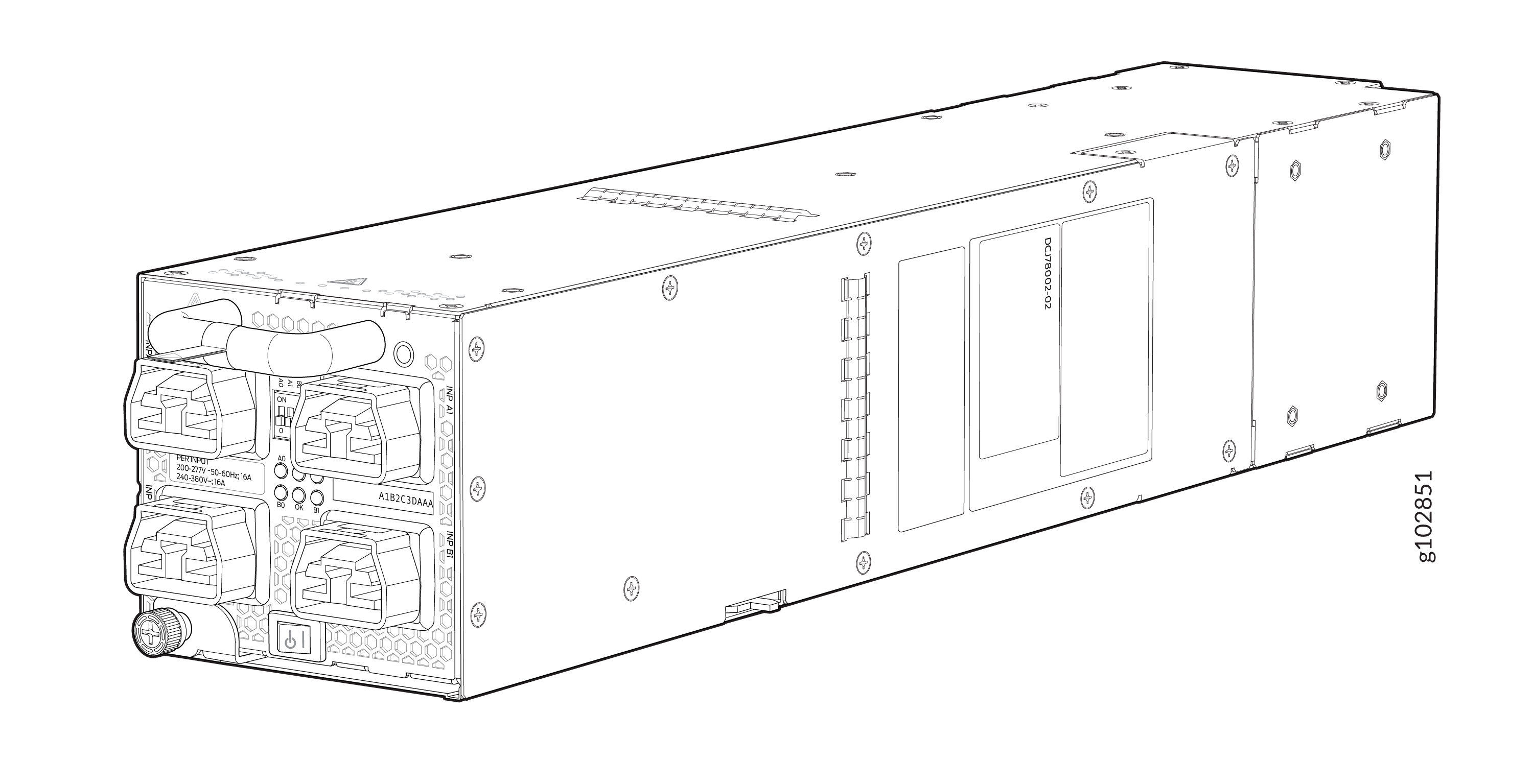
Input—The power supply unit takes four single-phase HVAC (180-305 VAC) or HVDC (190 - 410VDC) inputs (A0, A1, B0, and B1) at either 20 A or 15 A and provides a DC output of 12.3V. The input receptacle on the AC power supply unit (PSU) is IEC 320-C22. The mating connector on the power cord is IEC 320-C21.
Output—The power supply provides DC output of 12.3V at:
-
7800 W (20-A input) with three or four active feeds, or
-
6000 W (20-A input) with two active feeds (one source to either A0 or A1, and second source to either B0 or B1), or
-
3000 W (20-A input) with single active feed, or
-
7800 W (15-A input) with four active feeds, or
-
6900 W (15-A input) with three active feeds, or
-
4600 W (15-A input) with two active feeds, or
-
2300 W (15-A input) with single active feed.
-
The operating input voltage range is 180 to 264 VAC for AC systems. The DC output is 12.3 VDC.
-
The number of power feeds and whether the power supplies provide high-output (20-A) or low-output (15-A) power are configured using a set of dual inline package (DIP) switches on the faceplate of the power supply. If one power supply in the chassis is set to low power, the power budget for the chassis is reduced to low power, regardless of their DIP switch settings or the output results in the CLI. This design safeguards against accidentally setting the power supply to 20 A in a facility that can provide only 15 A and tripping the facility circuit breaker. We recommend that you don’t mix DIP switch settings in your system. See Table 2 for information about the input and output voltages when you use the DIP switches.
-
The JNP10K-PWR-AC3H power supply has an ENABLE switch on the front panel to enable/disable the main 12.3 VDC output and +5.0 V_BIAS standby output as well. If the switch is in DISABLE position, the front-end PFC will be disabled to minimize power consumption. This switch has the highest priority over any other shutdown method.
-
The Power Factor Correction (PFC) is PF 0.98 kW minimum at full load. The maximum inrush current is 50 A for the active feed.
JNP10K-PWR-BLN3 or Active Blank
Juniper Networks offers an Active Blank Power Module (ABPM), JNP10K-PWR-BLN3. This helps in airflow and cooling in the chassis. You can have the following combination of ABPM, passive blank, and JNP10K-PWR-AC3H power supply units (PSU) in the router chassis:
-
Three PSUs
-
Two PSUs with one ABPM
-
One PSU with one ABPMs and one passive blank
-
One PSU with two ABPMs
-
Table 26: PSU, ABPM, Passive Blank Matrix JNP10K-PWR-AC3H PSU(s)
ABPM (JNP10K-PWR-BLN3)
Passive Blank
3
-
-
2
1
-
1
1
1
1
2
-
Note:A minimum of one JNP10K-PWR-AC3H power supply unit (PSU) must be present in the router chassis.
The JNP10K-PWR-AC3H power supply has internal fans that contribute to chassis cooling. Three PSUs or two PSUs along with a ABPM must be present in a running chassis to have the adequate airflow. While the minimum power supplies are required to be present in the chassis, they all need not be necessarily connected to power source. If a power supply is installed in a slot but not connected to a power source, it draws power from the chassis to power the internal fans in the power supplies.
Extreme burn danger—The JNP10K-PWR-AC3H can reach temperatures in the range of 158°F to 176°F (70°C to 80°C) under running conditions.
The router is pluggable type A equipment installed in a restricted-access location. It has a separate protective earthing terminal on the chassis that must be connected to earth ground permanently to ground the chassis adequately and protect the operator from electrical hazards.
Before you begin installing the router, ensure that a licensed electrician has attached an appropriate grounding lug to the grounding cable that you supply. Using a grounding cable with an incorrectly attached lug can damage the router.
Use a 2-pole circuit breaker rated at 25 A in the building installation and the system, or as per local electrical code.
The JNP10K-PWR-AC3H Power Supplies have five dual position DIP switches (INP-A0, INP-A1, INP-B0, INP-B1, and DIP4) that are accessible from the front panel. DIP4 is the fifth DIP switch, which is used to indicate whether 20A or 15A input source is connected. See Figure 15 and Table 27 to know the layout of the DIP switches and the power output when the DIP switches are set in different combinations.
1—DIP switches
|
INP-A0 (Switch 0) |
INP-A1 (Switch 1) |
INP-B0 (Switch 2) |
INP-B1 (Switch 3) |
Switch 4 (High Input 20 A/Low Input 15 A) |
Output Power |
|---|---|---|---|---|---|
|
15-A |
|||||
|
Off |
Off |
Off |
On |
Off (15 A) |
2300 W |
|
Off |
Off |
On |
Off |
Off (15 A) |
2300 W |
|
Off |
Off |
On |
On |
Off (15 A) |
4600 W |
|
Off |
On |
Off |
Off |
Off (15 A) |
2300 W |
|
Off |
On |
Off |
On |
Off (15 A) |
4600 W |
|
Off |
On |
On |
On |
Off (15 A) |
6900 W |
|
Off |
On |
On |
Off |
Off (15 A) |
4600 W |
|
On |
Off |
Off |
Off |
Off (15 A) |
2300 W |
|
On |
Off |
Off |
On |
Off (15 A) |
4600 W |
|
On |
Off |
On |
Off |
Off (15 A) |
4600 W |
|
On |
Off |
On |
On |
Off (15 A) |
6900 W |
|
On |
On |
Off |
Off |
Off (15 A) |
4600 W |
|
On |
On |
Off |
On |
Off (15 A) |
6900 W |
|
On |
On |
On |
Off |
Off (15 A) |
6900 W |
|
On |
On |
On |
On |
Off (15 A) |
7800 W |
|
20-A |
|||||
|
Off |
Off |
Off |
On |
On (20 A) |
3000 W |
|
Off |
Off |
On |
Off |
On (20 A) |
3000 W |
|
Off |
Off |
On |
On |
On (20 A) |
6000 W |
|
Off |
On |
Off |
Off |
On (20 A) |
3000 W |
|
Off |
On |
Off |
On |
On (20 A) |
6000 W |
|
Off |
On |
On |
Off |
On (20 A) |
6000 W |
|
Off |
On |
On |
On |
On (20 A) |
7800 W |
|
On |
Off |
Off |
Off |
On (20 A) |
3000 W |
|
On |
Off |
Off |
On |
On (20 A) |
6000 W |
|
On |
Off |
On |
Off |
On (20 A) |
6000 W |
|
On |
Off |
On |
On |
On (20 A) |
7800 W |
|
On |
On |
Off |
Off |
On (20 A) |
6000 W |
|
On |
On |
Off |
On |
On (20 A) |
7800 W |
|
On |
On |
On |
Off |
On (20 A) |
7800 W |
|
On |
On |
On |
On |
On (20 A) |
7800 W |
It is important to connect the input feeds of the JNP10K-PWR-AC3H power supply to HVAC mains before powering-on the router.
JNP10K-PWR-AC3H Power Supply LEDs
The JNP10K-PWR-AC3H power supply has six LEDs on its faceplate: !, OK, A0, A1, B0, and B1. The numbered LEDs correspond to the four inputs (INP-A0, INP-A1, INP-B0, and INP-B1). Additionally, there are two more LEDs OK (Power OK) and !(Fault). These LEDs display information about the status of the power supply. See Figure 16.
1—LEDs on the JNP10K-PWR-AC3H Power Supply denoting:
-
! Fault
-
OK Power OK
-
A0 INP A0–Source input 1
-
A1 INP A1–Source input 2
-
B0 INP B0–Source input 3
-
B1 INP B1–Source input 4
Physical markings on the power supply are INP-A0,
INP-A1, INP-B0, and
INP-B1. These markings correspond to INP-A0, INP-A1, INP-B0, and
INP-B1 in the show chassis power output (see Table 28).
|
Physical Marking on JNP10K-PWR-AC3H |
Corresponding Physical LED Marking |
show chassis power Command |
|---|---|---|
|
INP A0 |
A0 |
INP-A0 |
|
INP A1 |
A1 |
INP-A1 |
|
INP B0 |
B0 |
INP-B0 |
|
INP B1 |
B1 |
INP-B1 |
Table 29 describes the LEDs on a JNP10K-PWR-AC3H power supply, color on the LED, state, and its meaning.
|
LED |
Color |
State |
Description |
|---|---|---|---|
|
A0 ( |
Yellow |
Solid |
One of the following:
|
|
Green |
Solid |
The power supply is functioning properly. |
|
|
A1 ( |
Yellow |
Solid |
One of the following:
|
|
Green |
Solid |
The power supply is functioning properly. |
|
|
B0 ( |
Yellow |
Solid |
One of the following:
|
|
Green |
Solid |
The power supply is functioning properly. |
|
|
B1 ( |
Yellow |
Solid |
One of the following:
|
|
Green |
Solid |
The power supply is functioning properly. |
|
|
OK (Power OK) |
Green |
Solid |
The power supply is functioning properly. |
| Green | Blinking |
The power supply is functioning properly but there is a mismatch in the corresponding DIP switch. Example: If A0 is receiving input power but the corresponding DIP switch 0 is not ON, then the LED will blink green. |
|
|
Yellow |
Blinking |
The power supply output has detected a fault. |
|
|
Unlit |
Off |
The power supply is switched off. |
|
|
! (Fault) |
Red |
Solid |
The power supply has failed and must be replaced. |
|
Unlit |
Off |
The power supply is functioning normally. |
Fault. Instead, the system keeps the PSM state online and raises an
alarm.JNP10K-PWR-AC3H Power Specifications
The JNP10K-PWR-AC3H power supply supports HVAC and HVDC.
Table 30 lists the power specifications for the HVAC and HVDC power supply (JNP10K-PWR-AC3H) used in a PTX10004 chassis.
|
Specification |
Value |
|---|---|
|
AC input voltage |
180–305 VAC (each feed) HVAC 190 – 410 VAC (each feed) HVDC |
|
Input current rating |
50 A |
|
DC output power |
12.3 V (HVAC) 12.9 V (HVDC) |
Table 31 shows the physical specifications for a JNP10K-PWR-AC3H power supply.
|
Specification |
Value |
|---|---|
|
Height |
3.386 in. (8.60 cm) |
|
Width |
3.584 in. (9.10 cm) |
|
Depth |
16.966 in (43.10 cm) |
|
Weight |
12.8 lbs (5.8 kg) |
MX10004 Grounding Cable and Lug Specifications
The router must be adequately grounded before power is connected to ensure proper operation and to meet safety and electromagnetic interference (EMI) requirements. To ground an MX10004 chassis, connect a grounding cable to earth ground and then attach it to the chassis grounding point on the rear of the chassis beneath.
You must install the MX10004 in a restricted-access location and ensure that the chassis is always properly grounded. The MX10004 has a two-hole protective grounding terminal provided on the chassis. Under all circumstances, use this grounding connection to ground the chassis. For AC-powered systems, you must also use the grounding wire in the AC power cord along with the two-hole grounding lug connection. This tested system meets or exceeds all applicable EMC regulatory requirements with the two-hole protective grounding terminal.
To comply with GR-1089 requirements, all intrabuilding copper cabling used for SFP+, QSFP+, and higher must be shielded and grounded at both ends.
Before router installation begins, a licensed electrician must attach a cable lug to the grounding cables that you supply. See Connect the MX10004 Router to Earth Ground. A cable with an incorrectly attached lug can damage the router.
Before you connect the router to earth ground, review the following information:
-
Two threaded inserts (PEM nuts) are provided on the lower rear of the chassis to connect the router to earth ground. The protective earthing terminals are spaced at 0.63 in. (16 mm) centers.
-
The grounding lug required is a Panduit LCD6-10A-L or equivalent (provided). The grounding lug accommodates 6 AWG (13.3 mm²) stranded wire. If one or more JNP10K-PWR-DC2 power supplies are installed in the chassis and set for high input (80 A), use the Panduit LCD4-14A-L or equivalent (provided). This lug accommodates 4 AWG (21.1 mm²) stranded wire. The 4 AWG (21.1 mm²) stranded wire should be rated 90° C or as specified by the local electrical code.
-
The grounding cable that you provide for an MX10004 must be the same size as, or heavier than, the input wire of each power supply. Minimum recommendations are 6 AWG (13.3 mm²) stranded copper wire, Class B; 90° C wire, or as specified by local code.