MX10004 Chassis
Learn about the MX10004 router chassis, the field replaceable units (FRUs), and the physical specifications of each component.
MX10004 Chassis Physical Specifications
The MX10004 modular chassis is a rigid sheet-metal structure that houses the other router components. You can mount up to six MX10004 routers in a standard 19-in. 4-post rack (42 U), provided that the rack can bear the combined weight and that adequate power and cooling is available. See Figure 1 to help identify the major components. See Table 1 for the physical specifications of the chassis of these components.
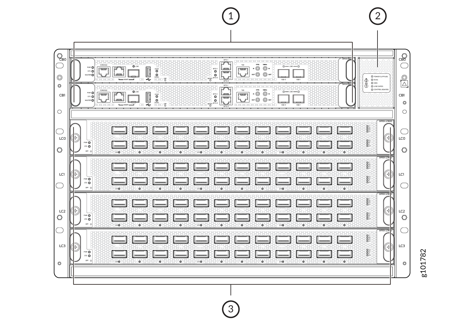
1 — RCBs | 3 — Line cards |
2 — Status panel |
The handles on each side of the chassis are not for lifting the chassis. These handles facilitate the fine-tune positioning of the chassis on the base brackets. Do not use the handles to lift the chassis, even when the chassis is empty. See Mount the Juniper Networks MX10004 Router Using the JNP10004-RMK-4POST Rack-Mount Kit or Mount the Juniper Networks MX10004 Router Using the JNP10K-RMK-4PST-XT Rack-Mount Kit for instructions about properly moving a loaded chassis.
|
Description |
Weight |
Height |
Width |
Depth |
|---|---|---|---|---|
|
Chassis, MX10004-BASE AC or DC configuration |
217 lbs (99 kg) |
12.2 in. (31 cm) |
17.4 in. (44.2 cm) Note:
The outer edges of the chassis flange extend the width to 19 in. (48.3 cm). |
36.7 in. (93.21 cm) with JNP10004-FAN2 or JNP10004-FAN3 fan trays 42.7 in. (108.5 cm) with EMI door |
|
Chassis MX10004-3F-BASE AC or DC configuration |
210 lbs (95 kg) |
12.2 in. (31 cm) |
17.4 in. (44.2 cm) Note:
The outer edges of the chassis flange extend the width to 19 in. (48.3 cm). |
36.7 in. (93.21 cm) with JNP10004-FAN2 or JNP10004-FAN3 fan trays 42.7 in. (108.5 cm) with EMI door |
|
Chassis MX10004-PREMIUM AC or DC configuration |
248 lbs (113 kg) |
12.2 in. (31 cm) |
17.4 in. (44.2 cm) Note:
The outer edges of the chassis flange extend the width to 19 in. (48.3 cm). |
36.7 in. (93.21 cm) with JNP10004-FAN2 or JNP10004-FAN3 fan trays 42.7 in. (108.5 cm) with EMI door |
|
Chassis redundant MX10004-4F-PREM AC or DC configuration |
239 lbs (108 kg) |
12.2 in. (31 cm) |
17.4 in. (44.2 cm) Note:
The outer edges of the chassis flange extend the width to 19 in. (48.3 cm). |
36.7 in. (93.21 cm) with JNP10004-FAN2 or JNP10004-FAN3 fan trays 42.7 in. (108.5 cm) with EMI door |
| MX10K-LC2101 line card |
31.57 lb (14.32 kg) |
1.89 in. (4.8 cm) |
17.2 in. (43.7 cm) |
19.05 in. (48.3 cm) (excluding FRU ejector) |
|
MX10K-LC480 Line Card |
21.6 lb (9.8 kg) |
1.89 in. (4.8 cm) |
17.2 in. (43.68 cm) |
19.05 in. (48.3 cm) (excluding FRU ejector) |
|
MX10K-LC9600 Line Card |
27 lb (12.24 kg) |
1.89 in. (4.8 cm) |
17.2 in. (43.68 cm) |
19.05 in. (48.3 cm) (excluding FRU ejector) |
|
MX10K-LC4800 Line Card |
40 lb (18.14 kg) |
1.89 in. (4.8 cm) |
17.2 in. (43.68 cm) |
19.05 in. (48.3 cm) (excluding FRU ejector) |
|
MX10K-LC4802 Line Card |
40 lb (18.14 kg) |
1.89 in. (4.8 cm) |
17.2 in. (43.68 cm) |
19.05 in. (48.3 cm) (excluding FRU ejector) |
MX10004 Field-Replaceable Units
Field-replaceable units (FRUs) are router components that you can replace at your site. The router uses the following types of FRUs:
-
Hot-insertable and hot-removable—You can remove and replace these components without powering off the router or disrupting the routing function.
-
Hot-pluggable—You can remove and replace these components without powering off the router, but the routing function is interrupted until you replace the component.
Table 2 lists the FRUs and their types for the MX10004 routers.
|
FRU |
Type |
|---|---|
|
Power supplies |
Hot-insertable and hot-removable. |
|
Fan trays |
Hot-insertable and hot-removable. |
|
Fan tray controllers |
Hot-insertable and hot-removable. |
|
Routing and Control Boards (RCBs) |
Redundant configuration:
Base configuration: Removal of the RCB causes the router to shut down. To prevent traffic disruption, take the chassis offline. If a temporary disruption is acceptable, you can install a replacement RCB in the second slot. The system restarts to elect a primary RCB and a backup RCBs If necessary, you can manually switch the primary and backup RCB using the |
|
Switch Fabric Boards (SFBs) |
SFBs are hot-insertable and hot-removable. We recommend that you take SFBs offline before removing them to avoid traffic loss while the router fabric is being reconfigured. Use the following command: request chassis sfb slot slot-number offline |
|
Line cards |
Hot-insertable. We recommend that you take line cards offline before removing them. Use the following command: request chassis fpc slot slot-number offline |
|
Optical transceivers |
Hot-insertable and hot-removable. |
Line cards are not part of the base or redundant configuration. You must order them separately.
If you have a Juniper Care service contract, register any addition, change, or upgrade of hardware components at https://www.juniper.net/customers/support/tools/updateinstallbase/. Failure to do so can result in significant delays if you need replacement parts. This note does not apply if you replace an existing component with the same type of component.
MX10004 Status Panel
The MX10004 status panel shows the overall status of the chassis.
The MX10004 chassis ships with an enhanced power bus to future-proof the chassis for potential power growth.
The status panel indicates the chassis status through a set of five bicolor LEDs. It has an Azure blue stripe along the left side of the LEDs. See Figure 2 for a chassis status panel.
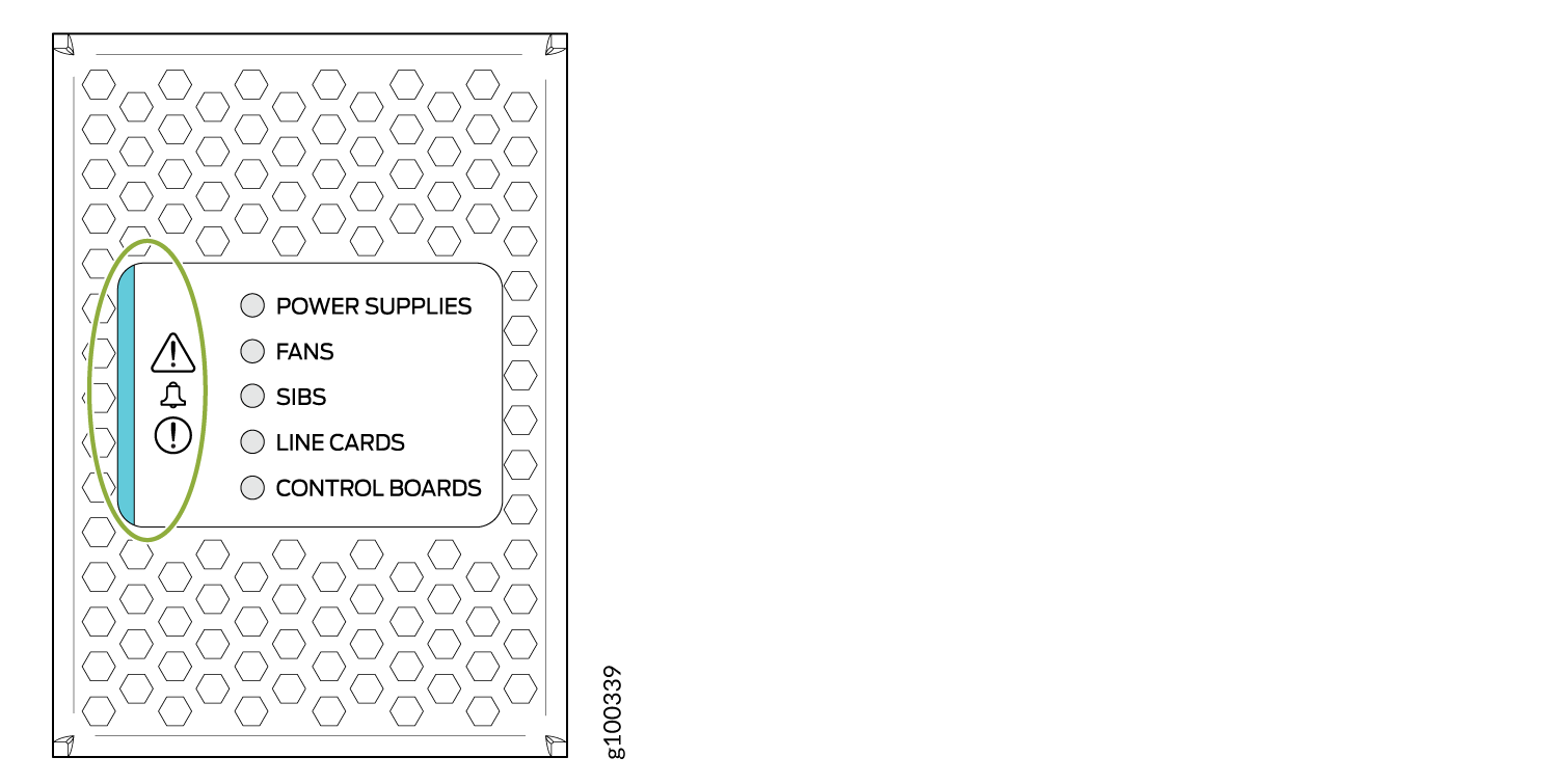
Table 3 describes the status panel LEDs.
|
Name |
Color |
State |
Description |
|---|---|---|---|
|
! Minor alarm (Triangle warning symbol) |
Yellow |
Off |
No minor alarms are active. |
|
On steadily |
A minor alarm is active. |
||
|
Alarm (Bell symbol) |
Yellow |
Off |
No minor alarms are active. |
|
On steadily |
A minor alarm is active. |
||
|
Red |
Off |
No major alarms are active. |
|
|
On steadily |
A major alarm is active. |
||
|
! Major alarm (Circle warning symbol) |
Red |
Off |
No major alarms are active. |
|
On steadily |
A major alarm is active. |
||
|
POWER SUPPLIES |
Green |
On steadily |
All of the power supplies are online and operating normally. |
|
Yellow |
Blinking |
One or more of the power supplies has an error. |
|
|
None |
Off |
None of the power supplies is receiving power. |
|
|
FANS |
Green |
On steadily |
The fans and the fan tray controllers are online and operating normally. |
|
Yellow |
Blinking |
An error occurred in a fan or in one of the fan tray controllers. |
|
|
None |
Off |
The fan tray controllers and fan trays are not receiving power. |
|
|
SIBS |
Green |
On steadily |
At least one installed Switch Fabric Board (SFB) is online. |
|
Yellow |
Blinking |
A hardware error occurred in one or more SFBs. |
|
|
None |
Off |
All the SFBs are offline. |
|
|
LINE CARDS |
Green |
On steadily |
All installed line cards are online. |
|
Yellow |
Blinking |
One or more line cards have an error. |
|
|
None |
Off |
All the line cards are offline. |
|
|
CONTROL BOARDS |
Green |
On steadily |
All installed Routing and Control Boards (RCBs) are online. |
|
Yellow |
Blinking |
One or more RCBs have an error condition. |
|
|
None |
Off |
The installed RCBs are offline. |
MX10004 Optional Equipment
The MX10004 routers offer the following optional equipment:
-
Line card cable management kit (JLC-CBL-MGMT-KIT)
-
JNP10004 replaceable air filter (JNP10004-FLTR)