Unpacking and Mounting the EX9204 Switch
Unpacking the EX9200 Switch
The switch is shipped in a wooden crate. A wooden pallet forms the base of the crate. The switch chassis is bolted to this pallet. Quick start installation instructions and a cardboard accessory box are also included in the shipping crate.
The switch is maximally protected inside the shipping box. Do not unpack it until you are ready to begin installation.
Ensure that you have the following parts and tools available:
Phillips (+) screwdrivers, number 1 and 2
1/2-in. or 13-mm open-end or socket wrench to remove bracket bolts from the shipping pallet
Cover panels to cover any slots not occupied by a component
To unpack the switch:
- Save the shipping crate cover, pallet, and packing materials
in case you need to move or ship the switch at a later time.
Figure 1 shows an EX9208 switch in the shipping crate. The contents are the same for all EX9200 switches.
Figure 1: Contents of the Shipping Crate for EX9200 Switches
Parts Inventory (Packing List) for an EX9204 Switch
The switch shipment includes a packing list. Check the parts you receive in the switch shipping crate against the items on the packing list. The packing list specifies the part number and provides description of each part in your order. The parts shipped depend on the configuration you order. See EX9204 Switch Configurations for more information.
If any part on the packing list is missing, contact your customer service representative or contact Juniper customer care from within the U.S. or Canada by telephone at 1-888-314-5822. For international-dial or direct-dial options in countries without toll-free numbers, see https://www.juniper.net/support/requesting-support.html .
All line cards ordered are shipped separately. Line cards are not listed on the switch’s packing list.
The base configuration is available only with AC power supplies. The redundant configuration ships with either AC or DC power supplies.
Table 1 lists the parts and their quantities in the packing list for a base configuration and a redundant configuration switch.
|
Component |
Base Configuration Quantity |
Redundant Configuration Quantity |
|---|---|---|
|
Chassis, including the midplane and front-mounting brackets |
1 |
1 |
|
Routing Engine module (RE module) |
1 |
2 |
|
Switch Fabric module (SF module) |
1 |
2 |
|
Power supplies |
One of the following:
|
One of the following:
|
|
Fan tray |
1 |
1 |
|
Air filter |
1 |
1 |
|
Cover panels for slots without installed components |
|
|
Table 2 lists the parts contained in the accessory box. The same accessories ship with both configurations of the switch.
|
Part |
Quantity |
|---|---|
|
Screws to mount chassis and small shelf |
22 |
|
DC power terminal Lugs, 6 WG |
5 |
|
Terminal block plug, 3-pole, 5.08 mm spacing, 12A, to connect the alarms |
2 |
|
Label, accessories contents, EX9204 |
1 |
|
Read me first document |
1 |
|
Affidavit for T1 connection |
1 |
|
Juniper Networks Product Warranty |
1 |
|
End User License Agreement |
1 |
|
Document sleeve |
1 |
|
Documentation Roadmap |
1 |
|
3 in. x 5 in. pink bag |
2 |
|
9 in. x 12 in. pink bag, ESD |
2 |
|
Accessory box, 19 in. x 12 in. x 3 in. |
1 |
|
ESD wrist strap with cable |
1 |
We no longer include the RJ-45 console cable with the DB-9 adapter as part of the device package. If the console cable and adapter are not included in your device package, or if you need a different type of adapter, you can order the following separately:
-
RJ-45 to DB-9 adapter (JNP-CBL-RJ45-DB9)
-
RJ-45 to USB-A adapter (JNP-CBL-RJ45-USBA)
-
RJ-45 to USB-C adapter (JNP-CBL-RJ45-USBC)
If you want to use RJ-45 to USB-A or RJ-45 to USB-C adapter you must have X64 (64-Bit) Virtual COM port (VCP) driver installed on your PC. See, https://ftdichip.com/drivers/vcp-drivers/ to download the driver.
Unpacking a Line Card Used in an EX9200 Switch
Before you unpack a line card:
Ensure that you have taken the necessary precautions to prevent electrostatic discharge (ESD) damage (see Prevention of Electrostatic Discharge Damage).
Ensure that you know how to handle and store the line card (see Handling and Storing Line Cards).
The line cards for EX9200 switches are rigid sheet-metal structures that house the line card components including network ports. The line cards are shipped in a cardboard carton, secured with foam packing material.
The line cards are maximally protected inside the shipping carton. Do not unpack the line cards until you are ready to install them in the switch chassis.
To unpack a line card (see Figure 2):
- Move the shipping carton to a staging area as close to the installation site as possible.
- Position the carton so that the arrows are pointing up.
- Open the top flaps on the shipping carton.
- Pull out the packing material, which holds the line card in place.
- Remove the line card from the antistatic bag.
- Save the shipping carton and packing materials in case you need to move or ship the line card later.
Update Base Installation Data
Update the installation base data if any addition or change to the installation base occurs or if the installation base is moved. Juniper Networks is not responsible for not meeting the hardware replacement SLA for products that do not have accurate installation base data.
Update your installation base at https://supportportal.juniper.net/s/CreateCase .
Installing and Connecting an EX9204 Switch
The EX9204 switch chassis is a rigid sheet-metal structure that houses the other hardware components such as Switch Fabric modules (SF modules), Routing Engine module (RE module), line cards, power supplies, fan tray, and air filter. The switch is shipped in a wooden crate. A wooden pallet forms the base of the crate.
To install and connect an EX9204 switch:
Installing a Mounting Shelf in a Rack or Cabinet for an EX9204 Switch
Ensure that you have the following parts and tools available to install the switch:
Cage nuts (optional) and mounting screws
Phillips (+) screwdrivers, number 1 and 2
Mounting shelf
The switch can be installed in a four-post rack or cabinet or in an open-frame rack.
We recommend that you install the mounting shelf, which is included in the shipping container, before installing the switch because the weight of a fully loaded chassis can be up to 128.0 lbs (58.1 kg).
Table 3 specifies the holes in which you insert cage nuts and screws to install the mounting hardware required (an X indicates a mounting hole location). The hole distances are relative to one of the standard U divisions on the rack. The bottom of all mounting shelves is at 0.02 in. above a U division.
Hole |
Distance Above U Division |
Mounting Shelf |
|
|---|---|---|---|
4 |
2.00 in. (5.1 cm) |
1.14 U |
X |
3 |
1.51 in. (3.8 cm) |
0.86 U |
X |
2 |
0.88 in. (2.2 cm) |
0.50 U |
X |
1 |
0.25 in. (0.6 cm) |
0.14 U |
X |
To install the mounting shelf on the front rails of a four-post rack or cabinet, or on the rails of an open-frame rack:
- If needed, install cage nuts in the holes specified in Table 3.
- On the back of each rack rail, partially insert a mounting screw into the lowest hole specified in Table 3.
- Install the mounting shelf on the back of the rack rails. Rest the bottom slot of each flange on a mounting screw.
- Partially insert the remaining screws into the open holes in each flange of the mounting shelf (see Figure 3 and Figure 4).
- Tighten all the screws completely.
Moving the Mounting Brackets for Center-Mounting an EX9200 Switch
Two removable mounting brackets are attached to the mounting holes closest to the front of the chassis. You can move the pair of brackets to another position on the side of the chassis for center-mounting the switch.
To move the mounting brackets from the front of the chassis toward the center of the chassis (see Figure 5, Figure 6, or Figure 7):
- Repeat the procedure for the other bracket.Figure 5: Moving the Mounting Brackets to the Center of the Chassis in an EX9204 Switch
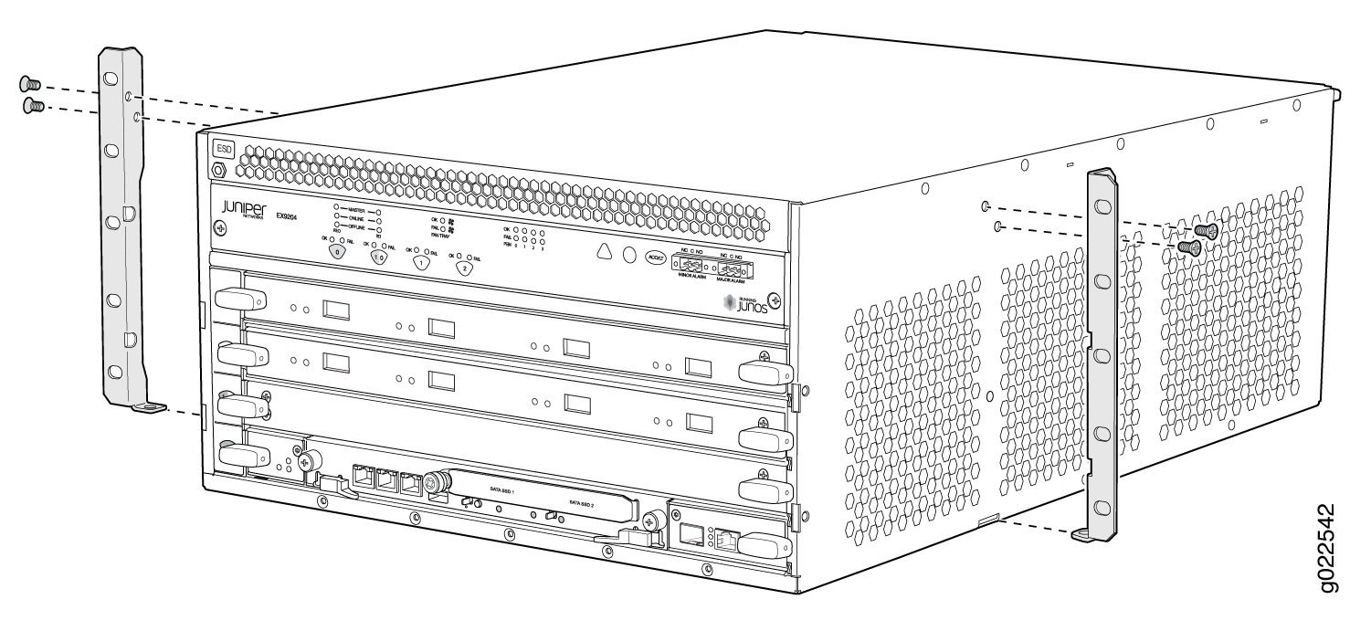 Figure 6: Moving the Mounting Brackets to the Center of the Chassis in an EX9208 Switch
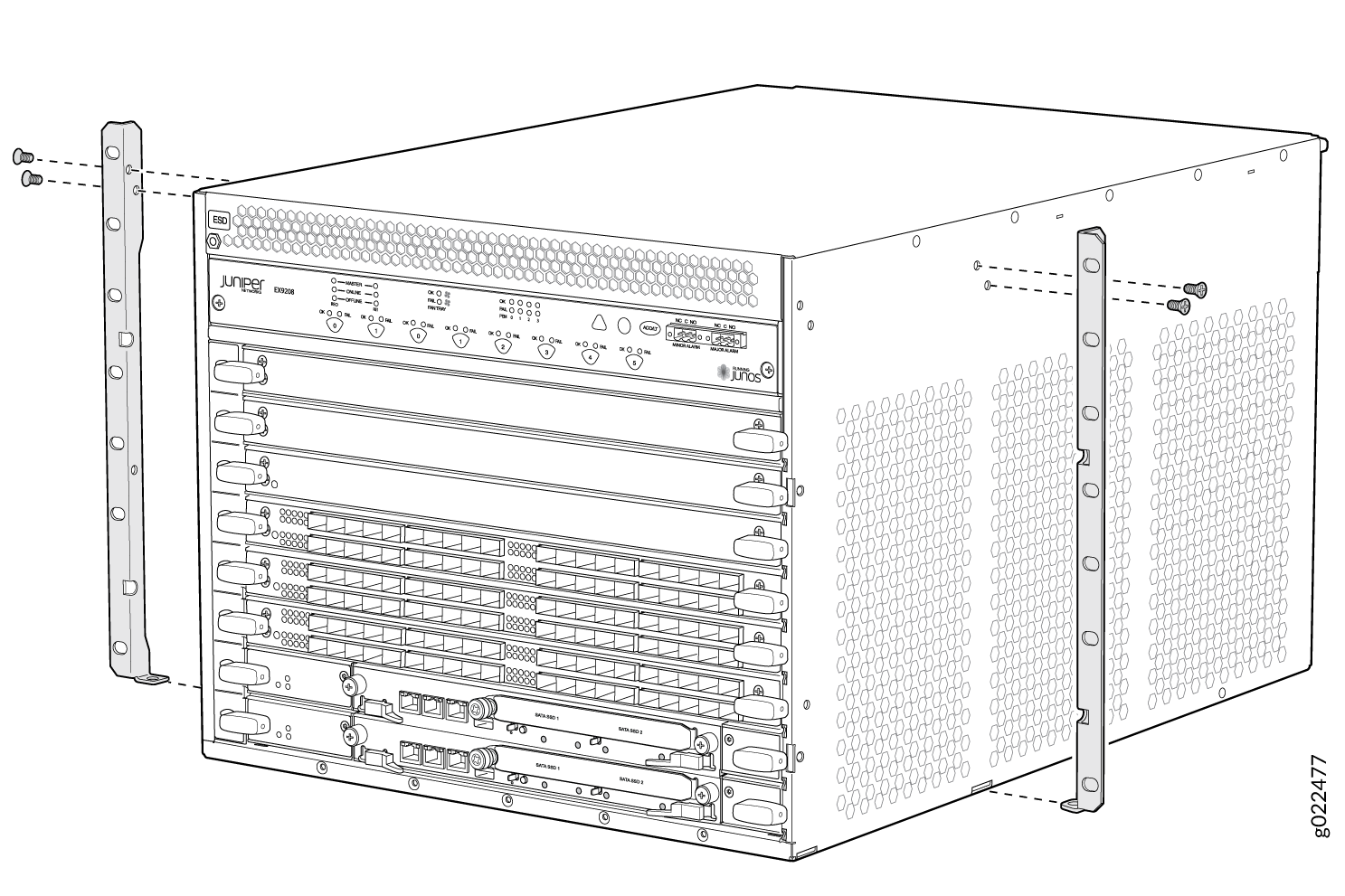 Figure 7: Moving the Mounting Brackets to the Center of the Chassis in an EX9214 Switch
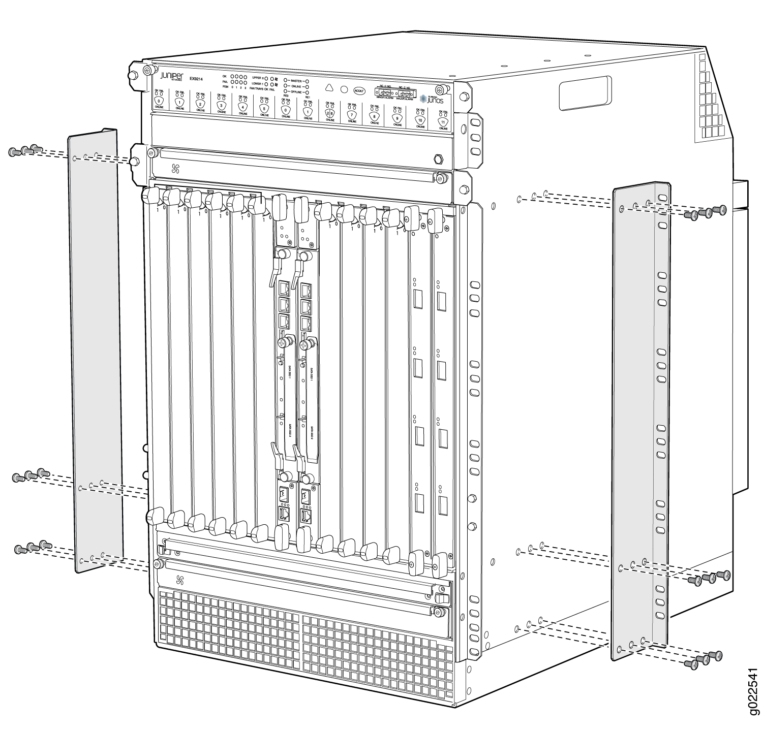
Mounting an EX9200 Switch on a Rack or Cabinet Using a Mechanical Lift
Before you install the switch:
Prepare the site for installation as described in Site Preparation Checklist for an EX9204 Switch, Site Preparation Checklist for an EX9208 Switch, or Site Preparation Checklist for an EX9214 Switch.
Ensure the site has adequate clearance for both airflow and hardware maintenance as described in Clearance Requirements for Airflow and Hardware Maintenance for an EX9204 Switch, Clearance Requirements for Airflow and Hardware Maintenance for an EX9208 Switch, or Clearance Requirements for Airflow and Hardware Maintenance for an EX9214 Switch.
Ensure you understand how to prevent electrostatic discharge (ESD) damage. See Prevention of Electrostatic Discharge Damage.
Unpack the switch as described in Unpacking the EX9200 Switch.
In a four-post rack or open-frame rack, install the mounting shelf. See Installing a Mounting Shelf in a Rack or Cabinet for an EX9204 Switch, Installing a Mounting Shelf in a Rack or Cabinet for an EX9208 Switch, or Installing a Mounting Shelf in a Rack or Cabinet for an EX9214 Switch.
Review chassis lifting guidelines described in Chassis Lifting Guidelines for EX9200 Switches.
Ensure that you have the following parts and tools available to install the switch:
A mechanical lift
7/16-in. (11-mm) nut driver
Phillips (+) screwdrivers, number 1 and 2
ESD grounding wrist strap
Because of the size and weight of the switch, we strongly recommend using a mechanical lift to install the switch.
Do not install line cards in the chassis until after you mount the chassis securely on a rack or cabinet.
Before front-mounting the switch on a rack or cabinet, have a qualified technician verify that the rack or cabinet is strong enough to support the weight of the switch and is adequately supported at the installation site.
If you are installing more than one switch in a rack or cabinet, install the first switch at the bottom of the rack.
To install the switch using a mechanical lift:
Figure 8 shows installing an EX9208 switch in an open-frame rack. The procedure is the same for all EX9200 switches.
See Also
Mounting an EX9204 Switch on a Rack or Cabinet Without Using a Mechanical Lift
To install the switch in the rack (see Figure 9):
If you are installing more than one switch in a rack, install the lowest one first. Installing a switch in an upper position in a rack or cabinet requires a lift.
Before front mounting the switch in a rack, have a qualified technician verify that the rack is strong enough to support the weight of the switch and is adequately supported at the installation site.
Lifting the chassis and mounting it in a rack requires two people. The empty chassis weighs approximately 52 lb (23.6 kg).
After you install the mounting screws and securely bolt the chassis to the rack, reinstall the components in the chassis. See: