EX9204 System Overview
EX9204 Switch Hardware Overview
Juniper Networks EX9204 Ethernet Switches provide high performance, scalable connectivity, and carrier-class reliability for high-density environments such as campus-aggregation and data-center networks. The EX9204 switch has a throughput of up to 1.6 terabits per second (Tbps) or up to 240 gigabits per second (Gbps) per slot full duplex.
You can manage EX9204 switches by using the same interfaces that you use for managing other devices running the Juniper Networks Junos operating system (Junos OS)—the CLI, the Network and Security Manager (NSM), and Junos Space.
In addition to the device CLI, the EX9200 switch can be managed and monitored by using Juniper Routing Director (formerly Juniper Paragon Automation).
- Benefits of the EX9204 Switch
- Software
- Front and Rear Views of an EX9204 Switch
- Host Subsystem
- Line Cards
- Cooling System
- Power Supplies
Benefits of the EX9204 Switch
Simplified network architecture—EX9204 switches deliver a simple, secure, virtualized network environment that increases business agility. They are ideal for simplifying campus, data center, and combined campus and data center network environments by collapsing network layers. In a multichassis link aggregation (MC-LAG) configuration in the campus, you can use EX9204 switches to eliminate Spanning Tree Protocol (STP); they collapse the core and aggregation layers, thereby simplifying the network architecture and network operations. In a data center, you can use EX9204 switches to collapse core and aggregation layers. In combined campus and data center environments, EX9204 switches consolidate network layers to simplify the network architecture and operations.
Support for MACsec—EX9200-40F-M and EX9200-40XS line cards and EX9200-20F-MIC for EX9200-MPC line card supports IEEE 802.1AE MACsec with AES-256 bit encryption, ensuring link-layer data confidentiality, data integrity, and data origin authentication.
Software
Juniper Networks EX Series Ethernet Switches run Junos OS, which provides Layer 2 and Layer 3 switching, routing, and security services.
Front and Rear Views of an EX9204 Switch
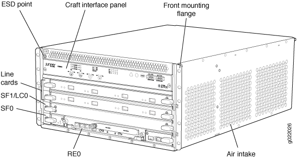
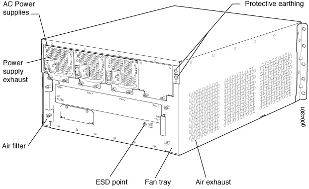
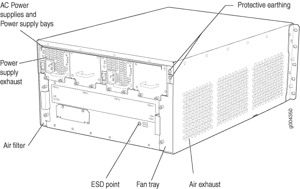
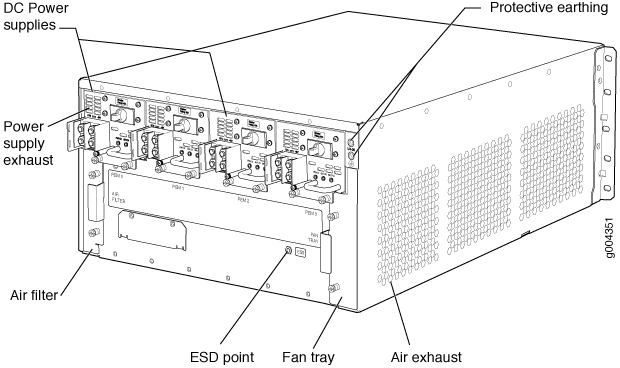
The EX9204 switch is five rack units (5 U) in size. Nine EX9204 switches can fit in a standard 48 U rack. Each EX9204 switch is designed to optimize rack space and cabling. See Figure 1, Figure 2, Figure 3, and Figure 4.


Host Subsystem
Switching and routing functionality, system management, and system control functions of an EX9204 switch are performed by the host subsystem. The host subsystem consists of a Routing Engine functioning together with a Switch Fabric.
An EX9204 is a 4-slot chassis that provides two dedicated slots—labeled 1 and 2—for line cards, one dedicated slot—labeled 0—for a host subsystem, and one multifunction slot—labeled 1|0—for either a line card or a host subsystem.
You can install either one or two host subsystems in an EX9204 switch. A base-configuration EX9204 switch has one host subsystem. A redundant-configuration EX9204 switch has a second host subsystem. For more information, see EX9204 Switch Configurations.
Line Cards
Line cards are field-replaceable units (FRUs) that you can install in the line card slots and in the multifunctional slot on the front of the switch chassis. All line cards are hot-removable and hot-insertable.
You can install up to three line cards in an EX9204 switch. Each EX9204 switch has two dedicated line card slots—labeled 1 and 2—and a multifunction slot—labeled 1|0—that you can use for either a line card or a host subsystem.
The line cards in EX9204 switches combine a Packet Forwarding Engine and Ethernet interfaces in a single assembly. Table 1 lists the line cards available for EX9204 switches.
|
Model |
Description |
Additional Information |
|---|---|---|
|
EX9200-2C-8XS |
A line card with two 100-Gigabit Ethernet ports and eight 10-Gigabit Ethernet ports |
|
|
EX9200-4QS |
A line card with four 40-Gigabit Ethernet ports |
|
|
EX9200-6QS |
A line card with six 40-Gigabit Ethernet ports and 24 10-Gigabit Ethernet ports |
|
|
EX9200-MPC |
A modular line card that accepts any of the following MICs:
|
|
|
EX9200-12QS |
A line card with six 40-Gigabit Ethernet rate-selectable ports, each of which can house transceivers |
|
|
EX9200-15C |
line card with 15 rate-selectable ports. All ports can operate at 10-Gbps, 25-Gbps, 40-Gbps, or 100-Gbps speeds |
|
|
EX9200-32XS |
A line card with 32 10-Gigabit Ethernet ports |
|
|
EX9200-40T |
A line card with 40 10/100/1000BASE-T ports that support RJ-45 connectors |
|
|
EX9200-40F |
A line card with 40 1-Gigabit Ethernet ports |
|
|
EX9200-40F-M |
A line card with 40 1-Gigabit Ethernet ports with Media Access Control Security (MACsec) capability |
|
|
EX9200-40XS |
A line card with 40 10-Gigabit Ethernet ports with Media Access Control Security (MACsec) capability, each of which can house 10-gigabit small form-factor pluggable plus (SFP+) transceivers |
Cooling System
The cooling system in an EX9204 switch is a field-replaceable unit (FRU). It consists of a hot-removable and hot-insertable fan tray. The fan tray contains three fans. The fan tray installs vertically on the right back of the chassis and provides side-to-side chassis cooling. See EX9204 Cooling System.
Power Supplies
Power supplies for the EX9204 switch are fully redundant, load-sharing, and hot-removable and hot-insertable FRUs. Each EX9204 switch chassis can hold up to four AC or up to two DC power supplies.
Table 2 shows the details of the power supplies available for EX9204 switches.
|
Power Supply |
Input Voltage |
Output Power |
|---|---|---|
|
2520 W AC |
Low-voltage line (100–120 VAC) |
1027 W |
|
High-voltage line (200–240 VAC) |
1590 W |
|
|
2400 W DC |
–40 VDC through –70 VDC |
2400 W to 2600 W |
A base-configuration EX9204 switch ships with two low-line (100–120 VAC) AC power supplies or one high-line (200–240 VAC) AC power supply. An AC-powered, redundant-configuration EX9204 switch ships with four low-line (100–120 VAC) or two high-line (200–240 VAC) AC power supplies. See AC Power Supply in an EX9204 Switch.
A DC-powered, redundant-configuration EX9204 switch ships with two DC power supplies. See DC Power Supply in an EX9204 Switch.
Do not mix AC and DC power supplies in the same chassis.
EX9204 Switch Configurations
Table 3 lists the three hardware configurations for an EX9204 switch—one base configuration (AC) and two redundant configurations (AC and DC)—and the components included in each configuration.
Switch Configuration |
Configuration Components |
First Junos OS Release |
|---|---|---|
EX9204-BASE3C-AC |
|
20.3R1 |
EX9204-RED3C-AC (redundant configuration with 2520 W AC power supplies) |
|
20.3R1 |
EX9204-RED3C-DC (redundant configuration with 2520 W DC power supplies) |
|
20.3R1 |
EX9204-BASE3B-AC |
|
17.1R1 |
EX9204-AC-BND2 (comprises EX9204-BASE3B-AC and line card EX9200-32XS, shipped separately as two items) |
|
17.1R1 |
EX9204-RED3B-AC (redundant configuration with 2520 W AC power supplies) |
|
17.1R1 |
EX9204-RED3B-DC (redundant configuration with 2520 W DC power supplies) |
|
17.1R1 |
EX9204-BASE3A-AC |
|
14.1 |
EX9204-REDUND3A-AC |
|
14.1 |
EX9204-AC-BND1 (comprises of EX9204-BASE3 and line card EX9200-32XS, shipped separtely as two items) |
|
14.1 |
EX9204-REDUND3A-DC |
|
14.1 |
EX9204-BASE-AC (base configuration with 2520 W AC power supplies) |
|
12.3R2 |
EX9204-REDUND-AC (redundant configuration with 2520 W AC power supplies) |
|
12.3R2 |
EX9204-REDUND-DC (redundant configuration with 2400 W DC power supplies) |
|
12.3R2 |
You can install up to three line cards (in any combination) in the switch.
Line cards are not part of the base or redundant configuration. You must order them separately.
Power cords and additional power supplies (AC or DC) must be purchased separately.
EX9204 Switch Hardware and CLI Terminology Mapping
This topic describes the hardware terms used in EX9204 switch documentation and the corresponding terms used in the Junos OS CLI. See Table 4.
Hardware Item (CLI) |
Description (CLI) |
Value (CLI) |
Item in Documentation |
Additional Information |
|---|---|---|---|---|
Chassis |
EX9204 |
– |
Switch chassis |
|
Midplane |
One of the following:
|
– |
Switch midplane |
|
FPM Board |
Front Panel Display |
– |
Craft interface |
|
PEM (n) |
One of the following:
|
n is a value in the range 0-3. The value corresponds to the power supply slot number. |
AC or DC power supply |
|
Routing Engine (n) |
One of the following:
|
n is a value in the range 0-1. In base configuration, only one entry appears. In redundant configuration, two entries appear; one for each Routing Engine module (RE module) installed in the chassis. |
RE module |
|
CB (n) |
One of the following:
|
n is a value in the range of 0-1. Multiple line items appear in the CLI if more than one Switch Fabric modules (SF modules) is installed in the chassis. CB0 and CB1 stand for SF modules. |
SF module |
|
FPC (n) |
Abbreviated name of the line card. One of the following:
|
n is a value in the range of 0-2. The value corresponds to the line card slot number in which the line card is installed. |
Line card (The switch does not have actual FPCs—the line cards are the FPC equivalents on the switch) |
|
MIC (n) |
Abbreviated name of the Modular Interface Card (MIC). One of the following if EX9200-MPC line card is installed:
|
n is a value in the range 0-1. |
Line card Note:
The switch does not have actual MICs except in the EX9200-MPC line card—the line cards are the MIC equivalents on the switch. EX9200-MPC is a modular line card that accepts any of the following MICs:
|
|
PIC (n) |
Abbreviated name of the Physical Interface Card (PIC). |
n is a value in the range 0-3. |
Line card (The switch does not have actual PICs.) |
|
Xcvr (n) |
Abbreviated name of the transceiver. |
n is a value equivalent to the number of the port in which the transceiver is installed. |
Optical transceivers |
|
Fan tray |
Enhanced Fan Tray |
– |
Fan tray |
Chassis Physical Specifications of an EX9204 Switch
The EX9204 switch chassis is a rigid sheet-metal structure that houses the other switch components. Table 5 summarizes the physical specifications of the EX9204 switch chassis.
Description |
Weight |
Height |
Width |
Depth |
|---|---|---|---|---|
Chassis |
Chassis with midplane, craft interface (front-panel display), fan tray, and air filter: 52.0 lb (23.6 kg) Maximum configuration: 128.0 lb (58.1 kg) |
8.7 in. (22.1 cm) |
17.5 in. (44.5 cm) |
24.5 in. (62.2 cm) (from front to chassis rear) |
Routing Engine module |
2.4 lb (1.09 kg) |
1.25 in. (3.2 cm) |
11 in. (27.9 cm) |
7.75 in. (19.7 cm) |
Switch Fabric module |
9.6 lb (4.4 kg) (with Routing Engine installed) |
1.25 in. (3.2 cm) |
17 in. (43.2 cm) |
22 in. (55.9 cm) |
EX9200-SF3 Switch Fabric module |
13.6 lb (6.2 kg) |
1.2 in. (3.05 cm) |
15.7 in. (39.87 cm) |
21.2 in. (53.85 cm) |
Fan Tray |
4.2 lb (1.9 kg) |
6.5 in. (16.5 cm) |
1.76 in. (4.5 cm) |
23.3 in. (59.2 cm) |
Air filter |
1.0 lb (0.5 kg) |
5.0 in. (12.7 cm) |
0.31 in. (0.8 cm) |
22.23 in. (56.5 cm) |
AC power supply |
6.6 lb (2.99 kg) |
1.75 in. (4.4 cm) |
14.5 in. (36.8 cm) |
4 in. (10.2 cm) |
DC power supply |
6.2 lb (2.81 kg) |
1.75 in. (4.4 cm) |
14.5 in. (36.8 cm) |
4 in. (10.2 cm) |
EX9200-2C-8XS line card |
19.4 lb (8.8 kg) |
1.25 in. (3.2 cm) |
17 in. (43.2 cm) |
22 in. (55.9 cm) |
EX9200-4QS line card |
16.8 lb (7.6 kg) |
1.25 in. (3.2 cm) |
17 in. (43.2 cm) |
22 in. (55.9 cm) |
EX9200-6QS line card |
21 lb (9.25 kg) |
1.25 in. (3.2 cm) |
17 in. (43.2 cm) |
22 in. (55.9 cm) |
EX9200-MPC line card |
15.96 lb (7.3 kg) |
1.25 in. (3.2 cm) |
17 in. (43.2 cm) |
22 in. (55.9 cm) |
EX9200-10XS-MIC |
1.54 lb (0.7 kg) |
1.25 in. (3.2 cm) |
6.67 in. (16.9 cm) |
7.86 in. (20 cm) |
EX9200-20F-MIC |
1.2 lb (0.54 kg) |
1.25 in. (3.2 cm) |
6.67 in. (16.9 cm) |
7.86 in. (20 cm) |
EX9200-40T-MIC |
1.9 lb (0.9 kg) |
1.25 in. (3.2 cm) |
13.36 in. (33.9 cm) |
22 in. (55.9 cm) |
EX9200-12QS line card |
15.7 lb (7.12 kg) |
1.25 in. (3.2 cm) |
17 in. (43.2 cm) |
22 in. (55.9 cm) |
EX9200-15C line card |
20.4 lb (9.25 kg) |
1.2 in. (3.05 cm) |
15.7 in. (39.87 cm) |
21.2 in. (53.85 cm) |
EX9200-32XS line card |
19.2 lb (8.7 kg) |
1.25 in. (3.2 cm) |
17 in. (43.2 cm) |
22 in. (55.9 cm) |
EX9200-40T line card |
14.0 lb (6.6 kg) |
1.25 in. (3.2 cm) |
17 in. (43.2 cm) |
22 in. (55.9 cm) |
EX9200-40F line card |
14.8 lb (6.7 kg) |
1.25 in. (3.2 cm) |
17 in. (43.2 cm) |
22 in. (55.9 cm) |
EX9200-40F-M line card |
14.8 lb (6.7 kg) |
1.25 in. (3.2 cm) |
17 in. (43.2 cm) |
22 in. (55.9 cm) |
EX9200-40XS line card |
17 lb (7.7 kg) |
1.25 in. (3.2 cm) |
17 in. (43.2 cm) |
22 in. (55.9 cm) |
You can mount an EX9204 switch on a standard 19-in. four-post rack or a standard 800-mm enclosed cabinet. You can mount up to eight EX9204 switches in a standard (48 rack unit (U)) rack.
Field-Replaceable Units in an EX9200 Switch
Field-replaceable units (FRUs) are switch components that you can replace at your site. The EX9200 switch uses the following types of FRUs:
Hot-insertable and hot-removable—You can remove and replace these components without powering off the switch or disrupting the switching function.
Hot-pluggable—You can remove and replace these components without powering off the switch, but the switching function is interrupted until you replace the component.
Table 6 lists the FRUs for the EX9200 switch and their types.
FRU |
Type |
|
|---|---|---|
Power supplies |
Hot-insertable and hot-removable. |
|
Fan tray and air filter |
Hot-insertable and hot-removable. |
|
Routing Engine module (RE module) |
Redundant configuration:
Base configuration:
See EX9204 Switch Configurations, EX9208 Switch Configurations, and EX9214 Switch Configurations. |
|
Switch Fabric module (SF module) |
Redundant configuration:
Base configuration:
See EX9204 Switch Configurations, EX9208 Switch Configurations, and EX9214 Switch Configurations. |
|
Line cards |
Hot-insertable and hot-removable. We recommend that you take the line cards offline before removing them. See Removing a Line Card from an EX9200 Switch. |
|
SFP, SFP+, QSFP+, and CFP transceivers See Pluggable Transceivers Supported on EX9200 Switches for the Junos OS release in which the transceivers were introduced. |
Hot-insertable and hot-removable. |
|
Line cards are not part of the base or redundant configuration. You must order them separately.
If you have a Juniper J-Care service contract, register any addition, change, or upgrade of hardware components at https://www.juniper.net/customers/support/tools/updateinstallbase/ . Failure to do so can result in significant delays if you need replacement parts. This note does not apply if you replace existing components with the same type of component.
