EX9214 Chassis
Understanding EX9214 Switch Component and Functionality Redundancy
The Juniper Networks EX9214 Ethernet Switch is available as a fully redundant system. A redundant EX9214 switch configuration is so designed that no single point of failure can cause the entire switch to fail. See EX9214 Switch Configurations.
The following hardware components provide redundancy to an EX9214 switch:
Host subsystem—The host subsystem consists of a Routing Engine functioning together with a Switch Fabric. The host subsystem performs switching and routing functionality, system management, and system control functions of the switch. Either two or three host subsystems can be installed in the switch. If two host subsystems are installed, one functions as the primary and the other functions as the backup. If the primary host subsystem (or either of its components) fails, the backup takes over as the primary. To operate, each host subsystem requires a Routing Engine module (RE module) installed directly into in a Switch Fabric module (SF module).
You can install up to 12 line cards in an EX9214 switch. You can install either a line card or an SF module in the slot nine (labeled 2 | 6). If you install a line card in slot nine (labeled 2 | 6), redundancy is not available for the host subsystem.
If the Routing Engines are configured for graceful switchover, the backup Routing Engine automatically synchronizes its configuration and state with the primary Routing Engine. Any update to the primary Routing Engine state is replicated on the backup Routing Engine. If the backup Routing Engine assumes primary role, packet forwarding continues through the switch without interruption.
AC power supplies—You can install either two or four AC power supplies vertically at the rear of the chassis in slots PEM0 through PEM3 (left to right). The power supplies operate in two zones: power supplies in slots PEM0 and PEM2 provide power to the lower fan tray, line-card slots 6 through 11, and switch fabric slots 1 and 2; power supplies in slots PEM1 and PEM3 provide power to the upper fan tray, line-card slots 0 through 5, and switch fabric slot 0. There must be at least one power supply in each zone. Four power supplies provide full redundancy. If a power supply in a redundant configuration is removed or fails, its redundant power supply takes over without interruption. The power supply in PEM2 serves as redundant power supply to the power supply in slot PEM0 and the power supply in PEM3 serves as redundant power supply to the power supply in slot PEM1. If only two power supplies are installed, they must be installed in slots PEM0 and PEM1 or in slots PEM2 and PEM3. See AC Power Supply in an EX9214 Switch.
DC power supplies—You can install four DC power supplies vertically at the rear of the chassis in slots PEM0 through PEM3 (left to right). The power supplies operate in two zones: power supplies in slots PEM0 and PEM2 provide power to the lower fan tray, line-card slots 6 through 11, and switch fabric slots 1 and 2; power supplies in slots PEM1 and PEM3 provide power to the upper fan tray, line-card slots 0 through 5, and switch fabric slot 0. There must be at least one power supply in each zone. Four power supplies provide full redundancy. If a power supply in a redundant configuration is removed or fails, its redundant power supply takes over without interruption. The power supply in PEM2 serves as redundant power supply to the power supply in slot PEM0 and the power supply in PEM3 serves as redundant power supply to the power supply in slot PEM1. See DC Power Supply in an EX9214 Switch.
Cooling system—The cooling system in an EX9214 switch consists of two fan trays and one air filter. Each fan tray contains six fans. Under normal operating conditions, the fans in the fan trays run at less than full speed. If one of the fans fails, the host subsystem increases the speed of the remaining fans to provide sufficient cooling for the switch indefinitely. See EX9214 Cooling System.
Craft Interface in an EX9200 Switch
The craft interface enables you to view status and troubleshooting information at a glance and to perform many system control functions. The craft interface is located on the front panel of the switch. It contains LEDs and on and off buttons for switch components, the alarm relay contacts, and an alarm cutoff button.
Figure 1 shows the craft interface in an EX9204 switch. Figure 2 shows the craft interface in an EX9208 switch. Figure 3 shows the craft interface in an EX9214 switch.
1 — Host subsystem LEDs | 5 — Major alarm LED |
2 — Fan LEDs | 6 — Alarm cutoff/lamp test button |
3 — Power supply LEDs | 7 — Alarm relay contacts |
4 — Minor alarm LED | 8 — LEDs and control buttons for Switch Fabric and Line cards |
You can install a line card or an SF module in the multifunctional slot labeled 1|0 in EX9204 switches. The corresponding LED displays information depending on the hardware installed in that slot.
1 — Host subsystem LEDs | 6 — Alarm cutoff/lamp test button |
2 — Fan LEDs | 7 — Alarm relay contacts |
3 — Power supply LEDs | 8 — Switch Fabric LEDs and control buttons |
4 — Minor alarm LED | 9 — Line card LEDs and control buttons |
5 — Major alarm LED |
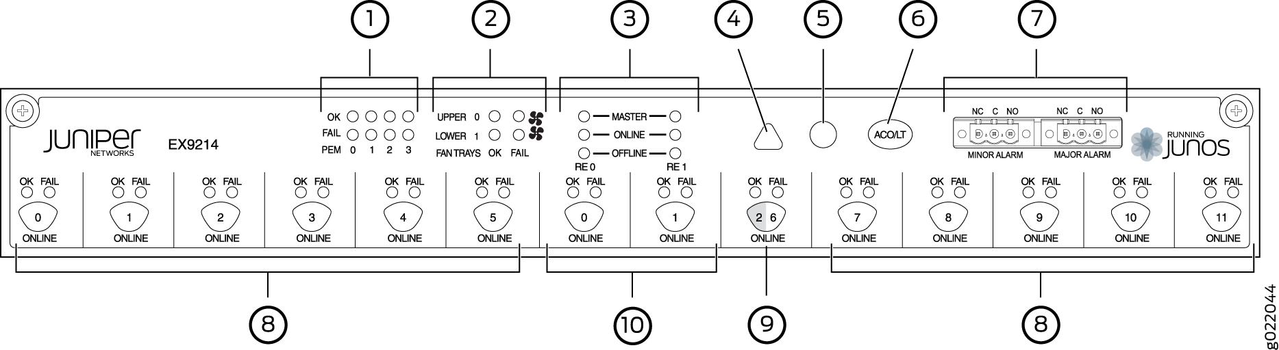
1 — Power supply LEDs | 6 — Alarm cutoff/lamp test button |
2 — Fan LEDs | 7 — Alarm relay contacts |
3 — Host subsystem LEDs | 8 — Line card LEDs and control buttons |
4 — Minor alarm LED | 9 — Switch Fabric/line card LED and control button |
5 — Major alarm LED | 10 — Switch Fabric LEDs and control buttons |
You can install a line card or a Switch Fabric module (SF module) in slot nine—labeled 2 | 6. The corresponding LED displays information depending on the hardware installed in that slot.
At least one Switch Fabric module (SF module) with a Routing Engine module (RE module) must be installed in the switch for the craft interface to obtain power.
The craft interface has the following components:
- Host Subsystem LEDs
- Fan LEDs
- Power Supply (PEM) LEDs
- Switch Fabric LEDs and Control Buttons
- Line Card LEDs and Control Buttons
- Alarm LEDs and Alarm Cutoff Button
- Alarm Relay Contacts
Host Subsystem LEDs
Each host subsystem (RE module with SF module) has three LEDs, located on the upper left of the craft interface, to indicate its status. The LEDs grouped with labels RE0 and RE1 show the status of the host subsystems installed in the switch. Table 1 describes the functions of these LEDs.
Label |
Status |
Description |
|---|---|---|
MASTER |
Green |
Host subsystem is functioning as the primary. |
Unlit |
Host subsystem is either functioning as the backup or not installed. |
|
ONLINE |
Green |
Host subsystem is online and is functioning normally. |
Unlit |
Host subsystem is either offline or not installed. |
|
OFFLINE |
Red |
Host subsystem is installed but Routing Engine is offline. |
Unlit |
Host subsystem is not installed. |
Fan LEDs
The fan LEDs are located on the top left of the craft interface. Table 2 describes the functions of the fan LEDs.
Label |
Status |
Description |
|---|---|---|
OK |
Green |
Fan is functioning normally. |
Unlit |
Fan is not installed. |
|
FAIL |
Red |
Fan has failed. |
Unlit |
Fan is not installed or functioning normally. |
Power Supply (PEM) LEDs
Each power supply has two LEDs on the craft interface that indicate its status. The LEDs—labeled 0 through 3—are located on the craft interface next to the PEM label. Table 3 describes the functions of the power supply LEDs on the craft interface.
Label |
Status |
Description |
|---|---|---|
OK |
Green |
Power supply is functioning normally. |
Off |
Power supply in not installed. |
|
FAIL |
Red |
Power supply has failed. |
Off |
Power supply is not installed or functioning normally. |
Switch Fabric LEDs and Control Buttons
Each Switch Fabric module has two LEDs on the craft interface that indicates its status. The LEDs—OK and FAIL—are associated with control buttons and are located along the bottom of the craft interface. You can turn the SF modules on or off by pressing these buttons on the craft interface.
Table 4 describes the status of the SF module LEDs.
Label |
Status |
Description |
|---|---|---|
OK |
Green |
On steadily—The SF module is functioning normally. |
Blinking—The SF module is coming online or going offline. |
||
Unlit |
The SF module is not online. |
|
FAIL |
Red |
The SF module has failed. |
Unlit |
The SF module is not installed or is not functioning normally. |
Line Card LEDs and Control Buttons
Each line card has two LEDs—OK and FAIL—on the craft interface that indicates its status. The line card LEDs are associated with control buttons and are located along the bottom of the craft interface. You can turn a line card online or offline by using its control button on the craft interface. Table 5 describes the function of the line card LEDs.
Label |
Status |
Description |
|---|---|---|
OK |
Green |
On steadily—Line card is functioning normally. |
Blinking—Line card is coming online or going offline. |
||
Unlit |
Line card is not online. |
|
FAIL |
Red |
Line card has failed. |
Unlit |
Line card is not installed or functioning normally. |
Alarm LEDs and Alarm Cutoff Button
Two large alarm LEDs are located at the upper right of the craft interface. The circular LED called major alarm LED glows to indicate a critical condition that can result in a system shutdown. The triangular LED called minor alarm LED glows to indicate a less severe condition (warning) that requires monitoring or maintenance. Both LEDs can be lit simultaneously.
A condition that causes an LED to be lit also activates the corresponding alarm relay contact on the craft interface.
The alarm cutoff/lamp test (ACO/LT) button, located next to the alarm LEDs, is a control button for alarms. You can press the ACO/LT button to deactivate major and minor alarms. Deactivating an alarm turns off both LEDs and deactivates the device attached to the corresponding alarm relay contact on the craft interface.
Table 6 describes the alarm LEDs and the alarm cutoff/lamp test button.
Alarm LEDs and Button |
Status |
Description |
|---|---|---|
 Major alarm LED |
Red |
Indicates a critical condition that can cause the switch to stop functioning. Possible causes include component removal, failure, or overheating. |
 Minor alarm LED |
Yellow |
Indicates a serious but nonfatal error condition, such as warning for a maintenance or a significant increase in component temperature. |
 Alarm cutoff/lamp test button |
– |
Deactivates major and minor alarms. Causes all LEDs on the craft interface to light (for testing) when pressed and held. |
Alarm Relay Contacts
The craft interface has two alarm relay contacts for connecting the switch to external alarm devices. Whenever a system condition triggers either the critical (major alarm) or warning (minor alarm) alarm on the craft interface, the alarm relay contacts are also activated. The alarm relay contacts are located on the upper right of the craft interface.
Figure 4 shows the alarm relay contacts in EX9200 switches.
Midplane in an EX9200 Switch
The midplane is located on the rear of the chassis and forms the rear of the card cage. The Switch Fabric modules (SF modules) and line cards are installed into the midplane from the front of the chassis, and the power supplies install into the midplane from the rear of the chassis. The cooling system components also connect to the midplane.
The midplane performs the following major functions:
Provides a data path—Data packets are transferred across the midplane between the line cards through the Switch Fabric on the host subsystem.
Distributes power—The power supplies connect to the midplane, which distributes power to all the switch components.
Provides a signal path—The midplane provides the signal path to the line cards, Switch Fabric, and other system components for monitoring and control of the system.
Figure 5 shows the midplane in an EX9204 switch. Figure 6 shows the midplane in an EX9208 switch. Figure 7 shows the midplane in an EX9214 switch.
Cable Management Bracket in an EX9214 Switch
The cable management bracket (see Figure 8) consists of a tray with fourteen dividers for securing the cables connected to the line cards and Switch Fabric modules (SF modules). It is located below the line card and SF module slots. You can use cable strips or other ties to gently secure the cables to the cable management bracket.
You can pull the cable management bracket up and outward to lock it into the maintenance position, so you can access the lower fan tray and the air filter.