EX9214 Cooling System
The cooling system in an EX9214 switch consists of two field-replacable unit fan trays and an air filter that provide front-to-rear chassis cooling.
Fan Tray
The cooling system components work together to keep all switch components within the acceptable temperature range. See Figure 1 and Figure 2.
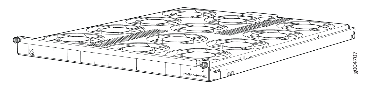
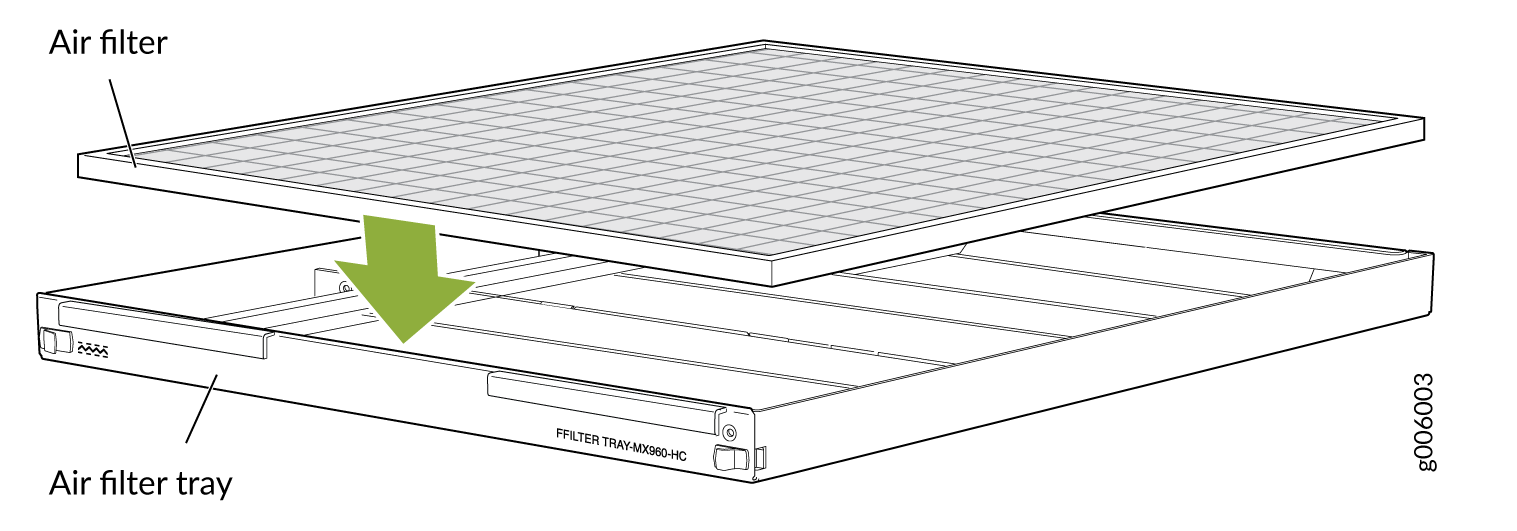
One of the fan trays is installed horizontally above the line card slots on the front panel and the other is installed horizontally above the air intake slot at the bottom of the front panel. The air filter is installed above the fan tray that is installed at the bottom of the front panel.
Airflow Direction in the EX9214 Switch Chassis
The air intake to cool the chassis is located on the front of the chassis, below the lower fan tray. Air is pulled through the chassis toward the fan tray, pushed up through the line card slots, and through the upper fan tray. See Figure 3.
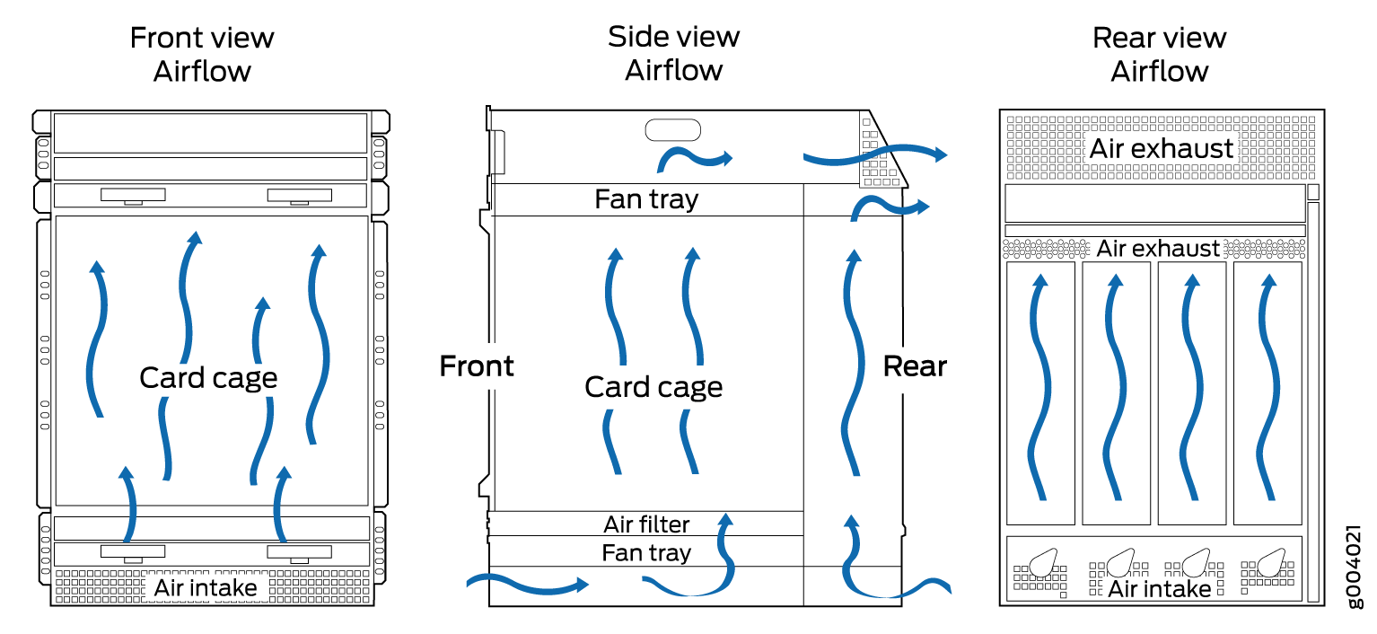
The host subsystem monitors the temperature of switch components. Under normal operating conditions, the fans in the fan tray run at less than full speed. If a fan fails or the ambient temperature rises above the threshold, the speed of the remaining fans is automatically adjusted to keep the temperature within the acceptable range. If the ambient maximum temperature specification is exceeded and the system cannot be adequately cooled, the Routing Engine shuts down the system by disabling output power from each power supply.
You cannot replace a single fan. If one or more fans fail, you must replace the entire fan tray.