Maintaining the EX9200 Cooling System
Removing a Fan Tray from an EX9200 Switch
Before you remove a fan tray:
Ensure you understand how to prevent electrostatic discharge (ESD) damage. See Prevention of Electrostatic Discharge Damage.
Ensure that you have the following parts and tools available:
ESD grounding strap
Phillips (+) screwdrivers, number 1 and 2
Replacement fan tray
The fan tray in an EX9200 switch is a hot-insertable and hot-removable field-replaceable unit (FRU): You can remove and replace it while the switch is running without turning off power to the switch or disrupting switching functions.
Do not remove the fan tray unless you have a replacement fan tray available.
To remove a fan tray from an EX9200 switch chassis:
Attach the ESD grounding strap to your bare wrist, and connect the strap to the ESD point on the chassis.
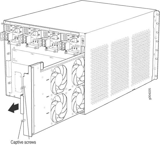
Loosen the captive screws on the fan tray faceplate using a screwdriver.
Grasp the fan tray handle, and pull it out approximately 1 to 3 inches.
Press the latch located on the inside of the fan tray to release it from the chassis.
Place one hand under the fan tray to support it, and pull the fan tray completely out of the chassis.
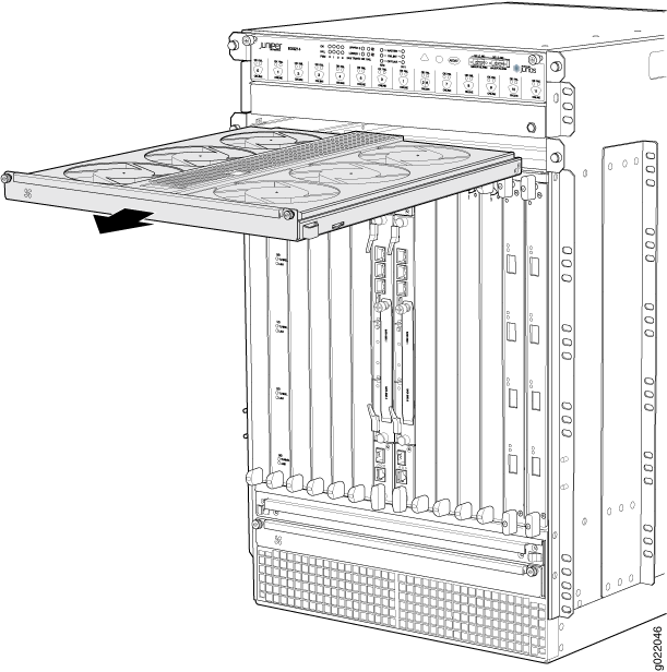
Figure 1 shows removing a fan try from an EX9208 switch. The procedure and orientation of the fan tray are the same for EX9204The procedure is the same for EX9214 switch; however, the orientation of the fan try is different— it is installed horizontally into the top and bottom of the chassis (see Figure 2).


Installing a Fan Tray in an EX9200 Switch
Before you begin to install a fan tray:
Ensure you understand how to prevent electrostatic discharge (ESD) damage. See Prevention of Electrostatic Discharge Damage.
Ensure that you have the following parts and tools available:
ESD grounding strap
Phillips (+) screwdrivers, number 1 and 2
The fan tray can be removed and replaced while the switch is operating. However, the fan tray must be replaced within 2 minutes of removing the fan tray to prevent the chassis from overheating.
The fan tray in an EX9200 switch is a hot-insertable and hot-removable field-replaceable unit (FRU): You can remove and replace it while the switch is running without turning off power to the switch or disrupting switching functions.
To install a fan tray in an EX9200 switch:
- Attach the ESD grounding strap to your bare wrist, and connect the strap to the ESD point on the chassis.
- Grasp the fan tray handle, and insert it straight into the chassis. Note the correct orientation by the This side up label on the top surface of the fan tray.
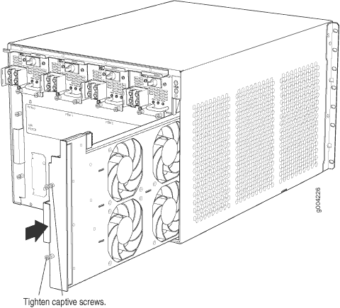
- Tighten the captive screws using a screwdriver on the fan tray faceplate to secure it in the chassis.
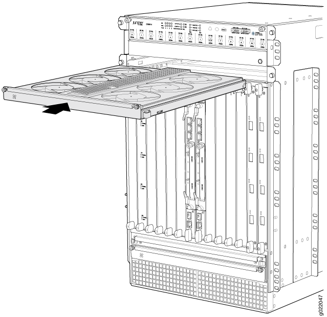
Figure 3 shows installing a fan try in an EX9208 switch. The procedure and orientation of the fan tray are the same for EX9204. The procedure is the same for EX9214 switch; however, the orientation of the fan try is different—it is installed horizontally into the top and bottom of the chassis (see Figure 4).


If you have a Juniper J-Care service contract, register any addition, change, or upgrade of hardware components at https://www.juniper.net/customers/support/tools/updateinstallbase/ . Failure to do so can result in significant delays if you need replacement parts. This note does not apply if you replace existing components with the same type of component.
Maintaining the Fan Tray in EX9200 Switches
Purpose
For optimum cooling, verify the condition of the fans.
Action
Monitor the status of the fans. A fan tray contains multiple fans that work in unison to cool the switch components. If one fan fails, the host subsystem adjusts the speed of the remaining fans to maintain proper cooling. A major alarm is triggered when a fan fails and a minor alarm and a major alarm are triggered when a fan tray is removed.
To display the status of the cooling system, issue the
show chassis environmentcommand. The output is similar to the following:user@switch> show chassis environment Class Item Status Measurement Temp PEM 0 OK 30 degrees C / 86 degrees F PEM 1 OK 35 degrees C / 95 degrees F PEM 2 Check PEM 3 Absent Routing Engine 0 OK 31 degrees C / 87 degrees F Routing Engine 0 CPU OK 30 degrees C / 86 degrees F Routing Engine 1 OK 33 degrees C / 91 degrees F Routing Engine 1 CPU OK 31 degrees C / 87 degrees F CB 0 Intake OK 30 degrees C / 86 degrees F CB 0 Exhaust A OK 29 degrees C / 84 degrees F CB 0 Exhaust B OK 36 degrees C / 96 degrees F CB 0 ACBC OK 34 degrees C / 93 degrees F CB 0 XF A OK 50 degrees C / 122 degrees F CB 0 XF B OK 46 degrees C / 114 degrees F CB 1 Intake OK 30 degrees C / 86 degrees F CB 1 Exhaust A OK 29 degrees C / 84 degrees F CB 1 Exhaust B OK 37 degrees C / 98 degrees F CB 1 ACBC OK 33 degrees C / 91 degrees F CB 1 XF A OK 50 degrees C / 122 degrees F CB 1 XF B OK 46 degrees C / 114 degrees F FPC 0 Intake OK 30 degrees C / 86 degrees F FPC 0 Exhaust A OK 36 degrees C / 96 degrees F FPC 0 Exhaust B OK 34 degrees C / 93 degrees F FPC 0 LU 0 TCAM TSen OK 40 degrees C / 104 degrees F FPC 0 LU 0 TCAM Chip OK 42 degrees C / 107 degrees F FPC 0 LU 0 TSen OK 40 degrees C / 104 degrees F FPC 0 LU 0 Chip OK 52 degrees C / 125 degrees F FPC 0 MQ 0 TSen OK 40 degrees C / 104 degrees F FPC 0 MQ 0 Chip OK 49 degrees C / 120 degrees F FPC 1 Intake OK 30 degrees C / 86 degrees F FPC 1 Exhaust A OK 35 degrees C / 95 degrees F FPC 1 Exhaust B OK 34 degrees C / 93 degrees F FPC 1 LU 0 TCAM TSen OK 40 degrees C / 104 degrees F FPC 1 LU 0 TCAM Chip OK 41 degrees C / 105 degrees F FPC 1 LU 0 TSen OK 40 degrees C / 104 degrees F FPC 1 LU 0 Chip OK 51 degrees C / 123 degrees F FPC 1 MQ 0 TSen OK 40 degrees C / 104 degrees F FPC 1 MQ 0 Chip OK 46 degrees C / 114 degrees F FPC 2 Intake OK 30 degrees C / 86 degrees F FPC 2 Exhaust A OK 35 degrees C / 95 degrees F FPC 2 Exhaust B OK 34 degrees C / 93 degrees F FPC 2 LU 0 TCAM TSen OK 40 degrees C / 104 degrees F FPC 2 LU 0 TCAM Chip OK 40 degrees C / 104 degrees F FPC 2 LU 0 TSen OK 40 degrees C / 104 degrees F FPC 2 LU 0 Chip OK 52 degrees C / 125 degrees F FPC 2 MQ 0 TSen OK 40 degrees C / 104 degrees F FPC 2 MQ 0 Chip OK 45 degrees C / 113 degrees F FPC 3 Intake OK 30 degrees C / 86 degrees F FPC 3 Exhaust A OK 34 degrees C / 93 degrees F FPC 3 Exhaust B OK 33 degrees C / 91 degrees F FPC 3 LU 0 TCAM TSen OK 39 degrees C / 102 degrees F FPC 3 LU 0 TCAM Chip OK 41 degrees C / 105 degrees F FPC 3 LU 0 TSen OK 39 degrees C / 102 degrees F FPC 3 LU 0 Chip OK 48 degrees C / 118 degrees F FPC 3 MQ 0 TSen OK 39 degrees C / 102 degrees F FPC 3 MQ 0 Chip OK 46 degrees C / 114 degrees F FPC 4 Intake OK 30 degrees C / 86 degrees F FPC 4 Exhaust A OK 36 degrees C / 96 degrees F FPC 4 Exhaust B OK 34 degrees C / 93 degrees F FPC 4 LU 0 TCAM TSen OK 40 degrees C / 104 degrees F FPC 4 LU 0 TCAM Chip OK 42 degrees C / 107 degrees F FPC 4 LU 0 TSen OK 40 degrees C / 104 degrees F FPC 4 LU 0 Chip OK 51 degrees C / 123 degrees F FPC 4 MQ 0 TSen OK 40 degrees C / 104 degrees F FPC 4 MQ 0 Chip OK 46 degrees C / 114 degrees F FPC 5 Intake OK 31 degrees C / 87 degrees F FPC 5 Exhaust A OK 35 degrees C / 95 degrees F FPC 5 Exhaust B OK 34 degrees C / 93 degrees F FPC 5 LU 0 TCAM TSen OK 41 degrees C / 105 degrees F FPC 5 LU 0 TCAM Chip OK 42 degrees C / 107 degrees F FPC 5 LU 0 TSen OK 41 degrees C / 105 degrees F FPC 5 LU 0 Chip OK 54 degrees C / 129 degrees F FPC 5 MQ 0 TSen OK 41 degrees C / 105 degrees F FPC 5 MQ 0 Chip OK 44 degrees C / 111 degrees F Fans Top Rear Fan OK Spinning at normal speed Bottom Rear Fan OK Spinning at normal speed Top Middle Fan OK Spinning at normal speed Bottom Middle Fan OK Spinning at normal speed Top Front Fan OK Spinning at normal speed Bottom Front Fan OK Spinning at normal speedThe output is of an EX9208 switch. The output is similar for all EX9200 switches.
See Also
Maintaining the Air Filter in EX9200 Switches
Purpose
For optimum cooling, verify the condition of the air filters.
Action
Regularly inspect the air filter. A dirty air filter restricts airflow in the unit, producing a negative effect on the ventilation of the chassis. The filter degrades over time. You must replace the filter every six months.
CAUTION:Always keep the air filter in place while the switch is operating. Because the fans are very powerful, they could pull small bits of wire or other materials into the switch through the unfiltered air intake. This could damage the switch components.
EX9200 switches ship with one air filter preinstalled. Spare air filters are separately orderable. The shelf life of the air filters vary from two to five years depending on the storage conditions. Store spare air filters in a dark, cool, and dry place. Wrap the air filters separately using plastic wraps and store them in an environment with RH between 40% to 80% and temperature between 40° F to 90° F. Storing air filters at higher temperatures or where they can be exposed to ultraviolet (UV) radiation, hydrocarbon emissions, or vapors from solvents can significantly reduce their life. If an air filter develops flakes or becomes brittle when rubbed or deformed, you must not use it.
