Connecting the EX9204 to Power
Connect Earth Ground to an EX Series Switch
To ensure proper operation and to meet electromagnetic interference (EMI) requirements, you must connect an EX Series switch to earth ground before you connect power to the switch. You must use the protective earthing terminal on the switch chassis to connect the switch to earth ground (see Figure 2).
You must install the EX Series switch in a restricted–access location and ensure that the chassis is always properly grounded. EX Series switches have a two–hole protective grounding terminal provided on the chassis. See Table 1 for the location of the earthing terminals on various EX Series switches. Under all circumstances, use this grounding connection to ground the chassis. For AC-powered systems, you must also use the grounding wire in the AC power cord along with the two-hole grounding lug connection. This tested system meets or exceeds all applicable EMC regulatory requirements with the two-hole protective grounding terminal.
Ensure that a licensed electrician has attached an appropriate grounding lug to the grounding cable you supply. Using a grounding cable with an incorrectly attached lug can damage the switch.
- Parts and Tools Required for Connecting an EX Series Switch to Earth Ground
- Special Instructions to Follow Before Connecting Earth Ground to an EX Series Switch
- Connecting Earth Ground to an EX Series Switch
Parts and Tools Required for Connecting an EX Series Switch to Earth Ground
Before you begin connecting an EX Series switch to earth ground, ensure you have the parts and tools required for your switch.
Table 1 lists the earthing terminal location, grounding cable and lug specifications, and parts needed for connecting an EX Series switch to earth ground.
|
Switch |
Earthing Terminal Location |
Grounding Cable Requirements |
Grounding Lug Specifications |
Screws and Washers |
Additional Information |
|---|---|---|---|---|---|
|
EX2200 |
Rear panel of the chassis |
14 AWG (2 mm²), minimum 90° C wire, or as permitted by the local code |
Panduit LCC10-14BWL or equivalent—not provided |
|
|
|
EX2300-C |
Rear panel of the chassis |
14 AWG (2 mm²), minimum 90° C wire, or as permitted by the local code |
Panduit LCC10-14AW-L or equivalent—not provided |
|
|
|
EX2300 |
Rear panel of the chassis |
|
|
|
|
|
EX3200 and EX3300 |
Rear panel of the chassis |
14 AWG (2 mm²), minimum 90° C wire, or as permitted by the local code |
Panduit LCC10-14BWL or equivalent—not provided |
|
For EX3200 Switches, see Special Instructions to Follow Before Connecting Earth Ground to an EX Series Switch. |
| EX3400 |
Rear panel of the chassis |
14-10 AWG STR (2.5-6 mm²), minimum 90° C wire, or as permitted by the local code |
Panduit LCD10-10A-L or equivalent—not provided |
|
|
|
EX4200 |
Left side of the chassis |
14 AWG (2 mm²), minimum 90° C wire, or as permitted by the local code |
Panduit LCC10-14BWL or equivalent—not provided |
|
See Special Instructions to Follow Before Connecting Earth Ground to an EX Series Switch. |
|
EX4300 switches except EX4300-48MP and EX4300-48MP-S switches |
Rear panel of the chassis |
14-10 AWG STR (2.5-6 mm²), minimum 90° C wire, or as permitted by the local code |
Panduit LCD10-10A-L or equivalent—not provided |
|
|
|
EX4300-48MP and EX4300-48MP-S switches |
Rear panel of the chassis |
14-10 AWG STR (2.5-6 mm²), minimum 90° C wire, or as permitted by the local code |
Panduit LCD10-14B-L, LCC10-BW-L, or equivalent—not provided |
|
|
|
EX4500 and EX4550 |
Left side of the chassis |
14 AWG (2 mm²), minimum 90° C wire, or as permitted by the local code |
Panduit LCC10-14BWL or equivalent—not provided |
|
See Special Instructions to Follow Before Connecting Earth Ground to an EX Series Switch. |
|
EX6210 |
Rear panel of the chassis (on lower left side) |
The grounding cable must be the same gauge as the power feed cables and as permitted by the local code. |
Panduit LCD2-14A-Q or equivalent—provided |
|
|
|
EX8208 |
Left side of the chassis |
6 AWG (13.3 mm²), minimum 90° C wire, or as permitted by the local code |
Panduit LCD2-14A-Q or equivalent—provided |
|
|
|
EX8216 |
Two earthing terminals:
Note:
You must use only one of the two protective earthing terminals. |
2 AWG (33.6 mm²), minimum 90° C wire, or as permitted by the local code |
Panduit LCD2-14A-Q or equivalent—provided |
|
|
|
EX9204, EX9208, and EX9214 |
Rear panel of the chassis |
One 6 AWG (13.3 mm²), minimum 90° C wire, or one that complies with the local code |
Thomas& Betts LCN6-14 or equivalent—provided |
|
See Grounding Cable and Lug Specifications for EX9200 Switches. |
|
EX9251 |
Rear panel of the chassis |
12 AWG (2.5 mm²), minimum 90° C wire, or one that complies with the local code—not provided |
Panduit LCD10-10A-L or equivalent—not provided |
Two 10-32 screws—provided |
See Grounding Cable and Lug Specifications for EX9200 Switches. |
|
EX9253 |
Right side of the chassis |
14-10 AWG (2-5.3 mm²), minimum 90° C wire, or one that complies with the local code—not provided |
Panduit LCD10-14B-L or equivalent—provided |
Two M5 Pan Head screws—provided |
Tools required for connecting an EX Series switch to earth ground:
-
An electrostatic discharge grounding strap (provided)
-
A Phillips (+) number 2 screwdriver to tighten the screws.
An AC–powered EX Series switch gains additional grounding when you plug the power supply in the switch into a grounded AC power outlet by using an AC power cord appropriate for your geographical location.
Special Instructions to Follow Before Connecting Earth Ground to an EX Series Switch
Table 2 lists the special instructions that you might need to follow before connecting earth ground to a switch.
|
Switch |
Special Instructions |
||||
|---|---|---|---|---|---|
|
EX3200 and EX4200 |
Some early variants of EX3200 and EX4200 switches for which the Juniper Networks model number on the label next to the protective earthing terminal is from 750-021xxx through 750-030xxx require 10-24x.25 in. screws. |
||||
|
EX4200, EX4500, and EX4550 |
If you plan to mount your switch on four posts of a rack or cabinet, mount your switch in the rack or cabinet before attaching the grounding lug to the switch. Note:
The protective earthing terminal on switches mounted on four posts of a rack is accessible through the slot on the left rear bracket only if the rack is 27.5 in. (69.85 cm) through 30.5 in. (77.47 cm) deep for a switch mounted flush with the rack front and 29.5 in. (74.93 cm) through 32.5 in. (82.55 cm) deep for a switch mounted 2 in. (5.08 cm) recessed from the rack front. See Figure 1. Figure 1: Connecting the Grounding Lug to a Switch Mounted on Four
Posts of a Rack
Note:
The brackets must be attached to the chassis before the grounding lug is attached. (The brackets are shown pulled away from the chassis so that the protective earthing terminal is seen.) |
Connecting Earth Ground to an EX Series Switch
To connect earth ground to an EX Series switch:
-
Verify that a licensed electrician has attached the cable lug to the grounding cable.
-
Connect one end of the grounding cable to a proper earth ground, such as the rack in which the switch is mounted.
-
Attach an ESD grounding strap to your bare wrist, and connect the strap to the ESD grounding point on the switch.
-
Place the grounding lug attached to the grounding cable over the protective earthing terminal. See Figure 2.
Figure 2: Connecting a Grounding Cable to an EX Series Switch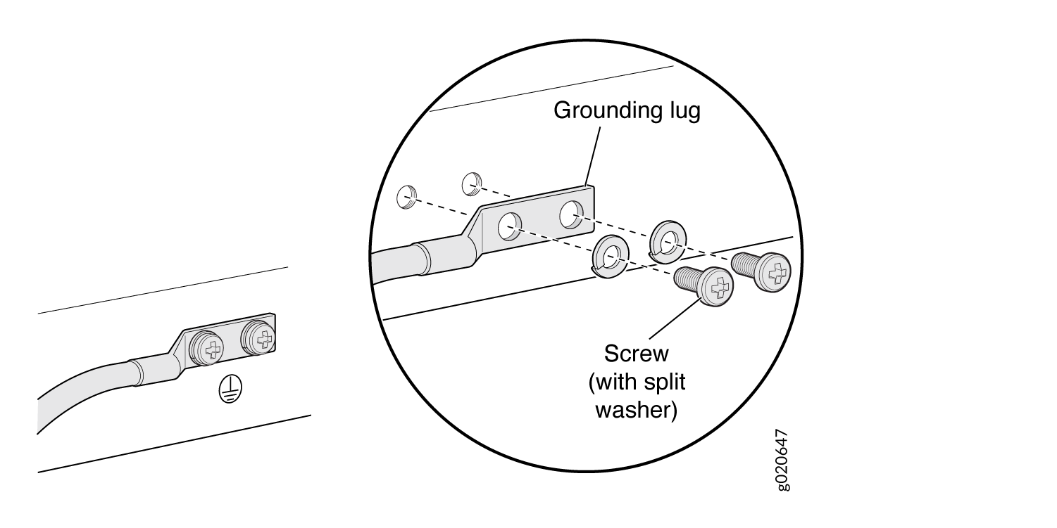
-
Secure the grounding lug to the protective earthing terminal with the washers and screws.
-
Dress the grounding cable and ensure that it does not touch or block access to other switch components and that it does not drape where people could trip over it.
See Also
Connecting AC Power to an EX9204 Switch
Before you begin to connect power to the switch:
Ensure you understand how to prevent electrostatic discharge (ESD) damage. See Prevention of Electrostatic Discharge Damage.
Ensure that you have connected the device chassis to earth ground.
CAUTION:For installations that require a separate grounding conductor to the chassis, have a licensed electrician complete this connection before you connect the switch to power. For instructions on connecting earth ground, see Connect Earth Ground to an EX Series Switch.
Install power supplies in the switch. See Installing an AC Power Supply in an EX9204 Switch.
Ensure that you have the following parts and tools available to connect power to the switch:
ESD grounding strap
Power cords appropriate for your geographical location (not provided). See AC Power Cord Specifications for an EX9204 Switch
Power cords are not provided with shipment; they must be purchased separately.
EX9204 switches can be configured with up to four AC power supplies.
Do not mix AC and DC power supplies in the same chassis.
Each power supply must be connected to a dedicated AC power source outlet.
Ensure that the power cords do not block access to switch components or drape where people can trip on them.
To connect AC power to an EX9204 switch (see Figure 3):
- Attach the ESD grounding strap to your bare wrist, and connect the strap to the ESD point on the chassis.
- Ensure that the power supply is fully inserted and latched securely in the chassis. See Installing an AC Power Supply in an EX9204 Switch.
- If needed, move the AC input switch next to the appliance inlet on the power supply faceplate, to the Off (O) position.
- Insert the coupler end of the power cord into the AC appliance inlet on the AC power supply faceplate.
- If the AC power source outlet has a power switch, set it to the Off (O) position.
- Insert the power cord plug into an AC power source outlet.
- If the AC power source outlet has a power switch, set it to the On (|) position.
- Move the AC input switch next to the appliance inlet on the power supply to the On (|) position and observe the status LEDs on the power supply faceplate. If the power supply is correctly installed and functioning normally, the AC OK and DC OK LEDs glow steady green, and the PS FAIL LED is not lit.
- Repeat steps 2 through 9 for the remaining power supplies.
See Also
Powering On an AC-Powered EX9200 Switch
Before you power on the switch, ensure that:
You have installed all required switch components.
You have installed the required number of power supplies to support redundant operation for the switch configuration.
You understand how to protect the switch from electrostatic discharge (ESD) damage . See Prevention of Electrostatic Discharge Damage.
Ensure that you have the following parts and tools available:
An ESD wrist strap
An external management device such as a PC
A cable to connect the external management device to the CONSOLE port or the Ethernet management <...> port on the primary Routing Engine module (RE module).
For connecting a management device to the console port, see Connecting an EX9200 Switch to a Management Console or an Auxiliary Device. For connecting a management device to the Ethernet management port, see Connecting an EX9200 Switch to a Network for Out-of-Band Management.
To power on the switch:
After you power on a power supply, wait for at least 60 seconds before you turn it off. After you power off a power supply, wait for at least 60 seconds before you turn it back on.
If the system is completely powered off when you switch on a
power supply, the RE module boots as the power supply completes its
startup sequence. If the Routing Engine finishes booting and you need
to power off the system again, first issue the CLI request system halt command.
After you power on a power supply, it can take up to 60 seconds
for status indicators such as power supply LEDs and the show chassis operational mode CLI command display to indicate that the power
supply is functioning normally. Ignore any error indicators that might
appear during the first 60 seconds.
Connecting DC Power to an EX9204 Switch
Before you begin connecting DC power to an EX9204 switch:
Ensure that you have taken the necessary precautions to prevent electrostatic discharge (ESD) damage (see Prevention of Electrostatic Discharge Damage).
Ensure that you have connected the switch chassis to earth ground.
CAUTION:To meet electromagnetic interference (EMI) requirements and to ensure proper operation, you must connect EX9204 switches to earth ground before you connect them to power. For installations that require a separate grounding conductor to the chassis, use the protective earthing terminal on the switch chassis to connect to earth ground. For instructions on connecting an EX9204 switch to ground using a separate grounding conductor, see Connect Earth Ground to an EX Series Switch.
Install the power supply in the chassis. See Installing a DC Power Supply in an EX9204 Switch.
Ensure that you have the following parts and tools available to connect DC power to an EX9204 switch:
ESD grounding strap
DC power source cables (not provided) with the cable lugs (provided) attached.
The provided cable lugs in an EX9204 switch are sized for 6 AWG (13.3 mm2) power source cables. The DC power source cables that you provide must be 6 AWG (13.3 mm2), minimum 60°C wire. We recommend that you install heat-shrink tubing insulation around the power cables and lugs.
3/8-in. (9.5-mm) nut driver or socket wrench
Phillips (+) screwdriver, number 1 and 2
Multimeter
An EX9204 switch can be configured with up to two DC power supplies.
Before performing DC power procedures, ensure that power is removed from the DC circuit. To ensure that all power is off, locate the circuit breaker on the panel board that services the DC circuit, switch the circuit breaker to the OFF position, and tape the switch handle of the circuit breaker in the OFF position.
Before you connect power to the switch, a licensed electrician must attach a cable lug to the grounding and power cables that you supply. A cable with an incorrectly attached lug can damage the switch (for example, by causing a short circuit).
Do not mix AC and DC power supplies in the same chassis.
Each power supply input feed must be connected to a dedicated DC power source outlet.
Ensure that the power cords do not block access to switch components or drape where people can trip on them.
To connect DC power to an EX9204 switch (see Figure 6):
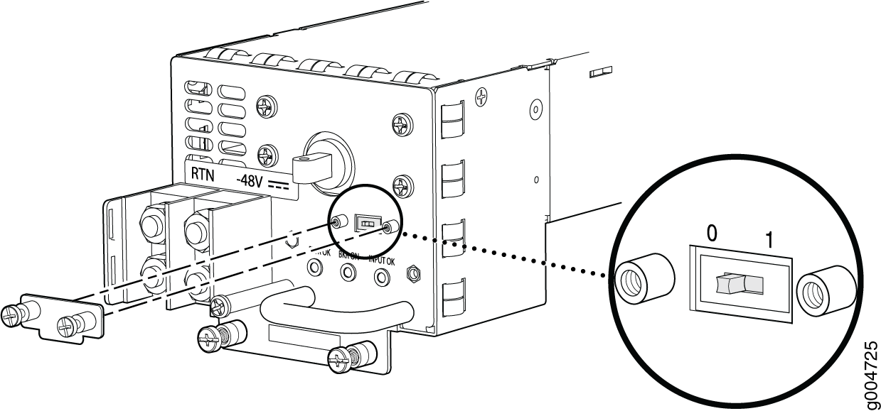
- Check the setting of the DIP input mode switch. Use a
sharp, nonconductive object to slide the switch to the desired position.
Set the input mode switch to position 0 for 60 A
input and position 1 for 70 A input (see Figure 4). This setting is used by the
power management software and needs to be set before you switch on
the power supply.Figure 4: DIP Input Mode Switch
-
Install heat-shrink tubing insulation around the power cables.
To install heat-shrink tubing:
-
Slide the tubing over the portion of the cable where it is attached to the lug barrel. Ensure that tubing covers the end of the wire and the barrel of the lug attached to it.
-
Shrink the tubing with a heat gun. Ensure that you heat all sides of the tubing evenly so that it shrinks around the cable tightly.
Figure 5 shows the steps to install heat-shrink tubing.
Note:Do not overheat the tubing.
Figure 5: How to Install Heat-Shrink Tubing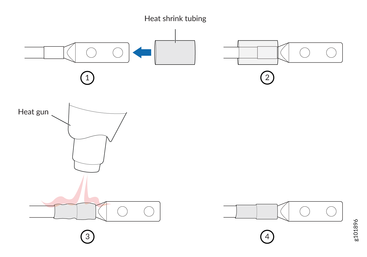
-
A Switch Fabric module must be installed for the PWR OK LED to function.
See Also
Powering On a DC-Powered EX9200 Switch
Before you power on the switch, ensure that:
You have installed all required switch components.
You have installed the required number of power supplies to support redundant operation for the switch configuration.
Ensure you understand how to prevent electrostatic discharge (ESD) damage. See Prevention of Electrostatic Discharge Damage.
Ensure that you have the following parts and tools available:
An ESD wrist strap
An external management device such as a PC
A cable to connect the external management device to the console (CONSOLE) port or the Ethernet management (<...>) port on the primary Routing Engine module (RE module).
For connecting a management device to the console port, see Connecting an EX9200 Switch to a Management Console or an Auxiliary Device. For connecting a management device to the management port, see Connecting an EX9200 Switch to a Network for Out-of-Band Management.
To power on the switch: