Connecting the EX2300 to Power
Connect Earth Ground to an EX Series Switch
To ensure proper operation and to meet electromagnetic interference (EMI) requirements, you must connect an EX Series switch to earth ground before you connect power to the switch. You must use the protective earthing terminal on the switch chassis to connect the switch to earth ground (see Figure 2).
You must install the EX Series switch in a restricted–access location and ensure that the chassis is always properly grounded. EX Series switches have a two–hole protective grounding terminal provided on the chassis. See Table 1 for the location of the earthing terminals on various EX Series switches. Under all circumstances, use this grounding connection to ground the chassis. For AC-powered systems, you must also use the grounding wire in the AC power cord along with the two-hole grounding lug connection. This tested system meets or exceeds all applicable EMC regulatory requirements with the two-hole protective grounding terminal.
Ensure that a licensed electrician has attached an appropriate grounding lug to the grounding cable you supply. Using a grounding cable with an incorrectly attached lug can damage the switch.
- Parts and Tools Required for Connecting an EX Series Switch to Earth Ground
- Special Instructions to Follow Before Connecting Earth Ground to an EX Series Switch
- Connecting Earth Ground to an EX Series Switch
Parts and Tools Required for Connecting an EX Series Switch to Earth Ground
Before you begin connecting an EX Series switch to earth ground, ensure you have the parts and tools required for your switch.
Table 1 lists the earthing terminal location, grounding cable and lug specifications, and parts needed for connecting an EX Series switch to earth ground.
|
Switch |
Earthing Terminal Location |
Grounding Cable Requirements |
Grounding Lug Specifications |
Screws and Washers |
Additional Information |
|---|---|---|---|---|---|
|
EX2200 |
Rear panel of the chassis |
14 AWG (2 mm²), minimum 90° C wire, or as permitted by the local code |
Panduit LCC10-14BWL or equivalent—not provided |
|
|
|
EX2300-C |
Rear panel of the chassis |
14 AWG (2 mm²), minimum 90° C wire, or as permitted by the local code |
Panduit LCC10-14AW-L or equivalent—not provided |
|
|
|
EX2300 |
Rear panel of the chassis |
|
|
|
|
|
EX3200 and EX3300 |
Rear panel of the chassis |
14 AWG (2 mm²), minimum 90° C wire, or as permitted by the local code |
Panduit LCC10-14BWL or equivalent—not provided |
|
For EX3200 Switches, see Special Instructions to Follow Before Connecting Earth Ground to an EX Series Switch. |
| EX3400 |
Rear panel of the chassis |
14-10 AWG STR (2.5-6 mm²), minimum 90° C wire, or as permitted by the local code |
Panduit LCD10-10A-L or equivalent—not provided |
|
|
|
EX4200 |
Left side of the chassis |
14 AWG (2 mm²), minimum 90° C wire, or as permitted by the local code |
Panduit LCC10-14BWL or equivalent—not provided |
|
See Special Instructions to Follow Before Connecting Earth Ground to an EX Series Switch. |
|
EX4300 switches except EX4300-48MP and EX4300-48MP-S switches |
Rear panel of the chassis |
14-10 AWG STR (2.5-6 mm²), minimum 90° C wire, or as permitted by the local code |
Panduit LCD10-10A-L or equivalent—not provided |
|
|
|
EX4300-48MP and EX4300-48MP-S switches |
Rear panel of the chassis |
14-10 AWG STR (2.5-6 mm²), minimum 90° C wire, or as permitted by the local code |
Panduit LCD10-14B-L, LCC10-BW-L, or equivalent—not provided |
|
|
|
EX4500 and EX4550 |
Left side of the chassis |
14 AWG (2 mm²), minimum 90° C wire, or as permitted by the local code |
Panduit LCC10-14BWL or equivalent—not provided |
|
See Special Instructions to Follow Before Connecting Earth Ground to an EX Series Switch. |
|
EX6210 |
Rear panel of the chassis (on lower left side) |
The grounding cable must be the same gauge as the power feed cables and as permitted by the local code. |
Panduit LCD2-14A-Q or equivalent—provided |
|
|
|
EX8208 |
Left side of the chassis |
6 AWG (13.3 mm²), minimum 90° C wire, or as permitted by the local code |
Panduit LCD2-14A-Q or equivalent—provided |
|
|
|
EX8216 |
Two earthing terminals:
Note:
You must use only one of the two protective earthing terminals. |
2 AWG (33.6 mm²), minimum 90° C wire, or as permitted by the local code |
Panduit LCD2-14A-Q or equivalent—provided |
|
|
|
EX9204, EX9208, and EX9214 |
Rear panel of the chassis |
One 6 AWG (13.3 mm²), minimum 90° C wire, or one that complies with the local code |
Thomas& Betts LCN6-14 or equivalent—provided |
|
See Grounding Cable and Lug Specifications for EX9200 Switches. |
|
EX9251 |
Rear panel of the chassis |
12 AWG (2.5 mm²), minimum 90° C wire, or one that complies with the local code—not provided |
Panduit LCD10-10A-L or equivalent—not provided |
Two 10-32 screws—provided |
See Grounding Cable and Lug Specifications for EX9200 Switches. |
|
EX9253 |
Right side of the chassis |
14-10 AWG (2-5.3 mm²), minimum 90° C wire, or one that complies with the local code—not provided |
Panduit LCD10-14B-L or equivalent—provided |
Two M5 Pan Head screws—provided |
Tools required for connecting an EX Series switch to earth ground:
-
An electrostatic discharge grounding strap (provided)
-
A Phillips (+) number 2 screwdriver to tighten the screws.
An AC–powered EX Series switch gains additional grounding when you plug the power supply in the switch into a grounded AC power outlet by using an AC power cord appropriate for your geographical location.
Special Instructions to Follow Before Connecting Earth Ground to an EX Series Switch
Table 2 lists the special instructions that you might need to follow before connecting earth ground to a switch.
|
Switch |
Special Instructions |
||||
|---|---|---|---|---|---|
|
EX3200 and EX4200 |
Some early variants of EX3200 and EX4200 switches for which the Juniper Networks model number on the label next to the protective earthing terminal is from 750-021xxx through 750-030xxx require 10-24x.25 in. screws. |
||||
|
EX4200, EX4500, and EX4550 |
If you plan to mount your switch on four posts of a rack or cabinet, mount your switch in the rack or cabinet before attaching the grounding lug to the switch. Note:
The protective earthing terminal on switches mounted on four posts of a rack is accessible through the slot on the left rear bracket only if the rack is 27.5 in. (69.85 cm) through 30.5 in. (77.47 cm) deep for a switch mounted flush with the rack front and 29.5 in. (74.93 cm) through 32.5 in. (82.55 cm) deep for a switch mounted 2 in. (5.08 cm) recessed from the rack front. See Figure 1. Figure 1: Connecting the Grounding Lug to a Switch Mounted on Four
Posts of a Rack
Note:
The brackets must be attached to the chassis before the grounding lug is attached. (The brackets are shown pulled away from the chassis so that the protective earthing terminal is seen.) |
Connecting Earth Ground to an EX Series Switch
To connect earth ground to an EX Series switch:
-
Verify that a licensed electrician has attached the cable lug to the grounding cable.
-
Connect one end of the grounding cable to a proper earth ground, such as the rack in which the switch is mounted.
-
Attach an ESD grounding strap to your bare wrist, and connect the strap to the ESD grounding point on the switch.
-
Place the grounding lug attached to the grounding cable over the protective earthing terminal. See Figure 2.
Figure 2: Connecting a Grounding Cable to an EX Series Switch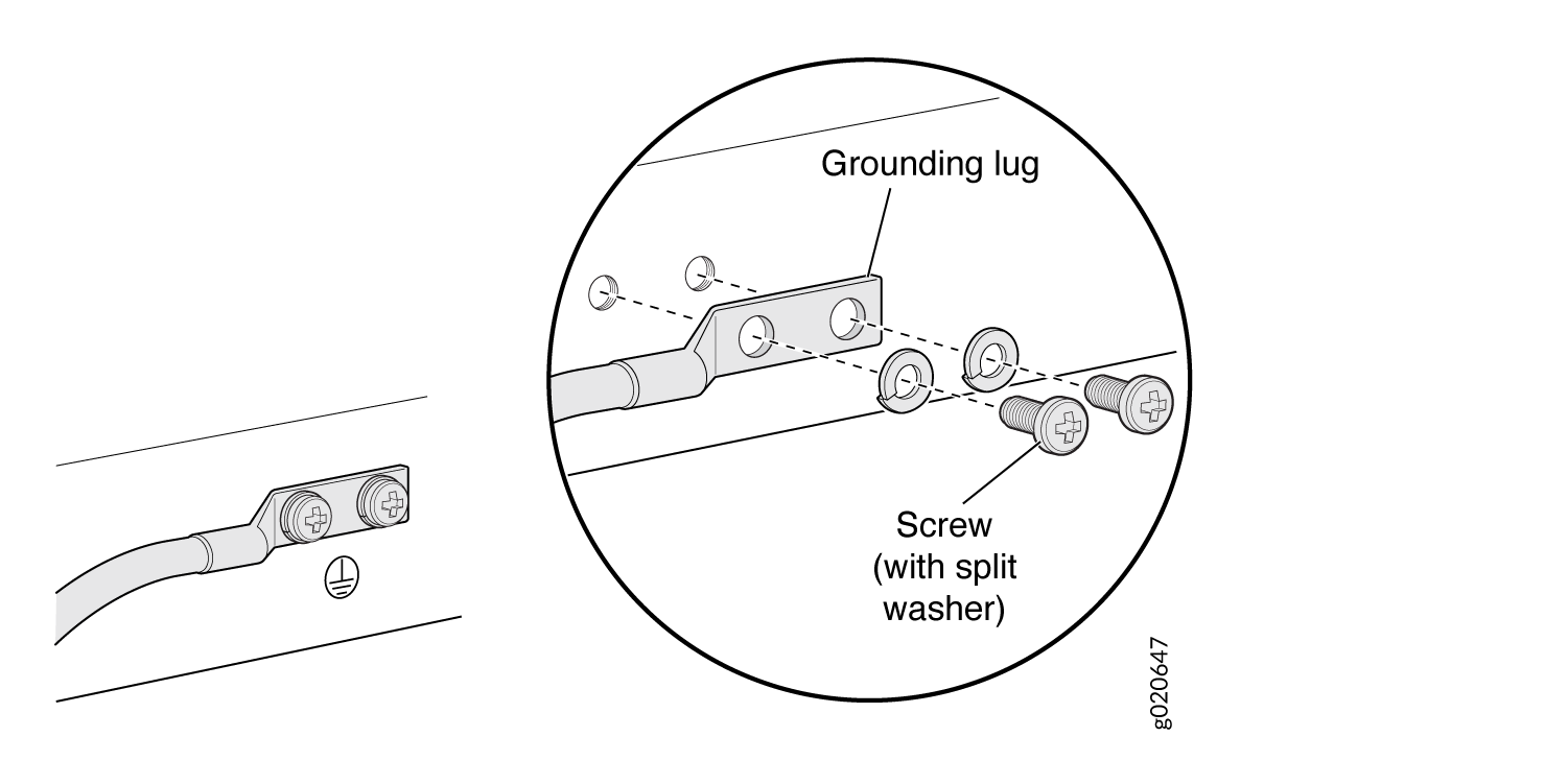
-
Secure the grounding lug to the protective earthing terminal with the washers and screws.
-
Dress the grounding cable and ensure that it does not touch or block access to other switch components and that it does not drape where people could trip over it.
See Also
Connecting AC Power to an EX2300 Switch
Ensure that you have the following parts and tools available:
-
A power cord appropriate for your geographical location
-
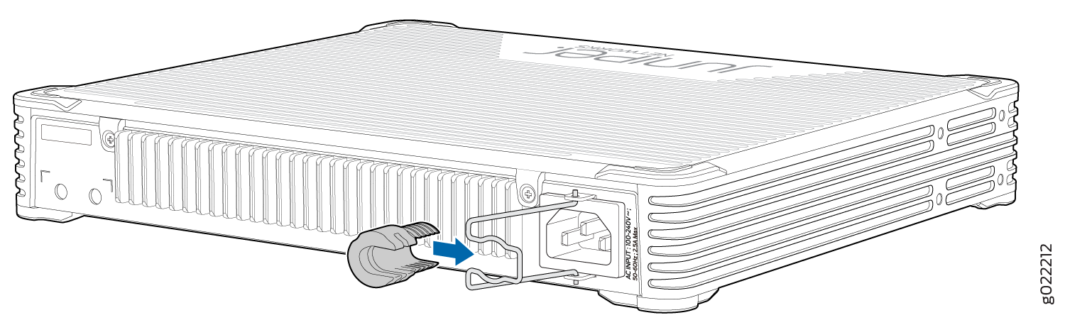
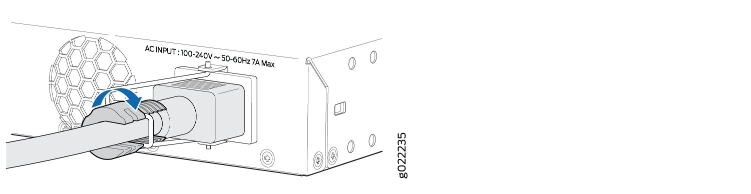
A power cord retainer clip (except for the EX2300-24MP model and the EX2300-48MP model)
Ensure that you have connected the device chassis to earth ground. The AC power cords provide additional grounding when you connect the power supply in the switch to a grounded AC power outlet by using the AC power cord appropriate for your geographical location (see AC Power Cord Specifications for EX2300 Switches).
For installations that require a separate grounding conductor to the chassis, have a licensed electrician complete this connection before you connect the switch to power. For instructions on connecting earth ground, see Connect Earth Ground to an EX Series Switch.
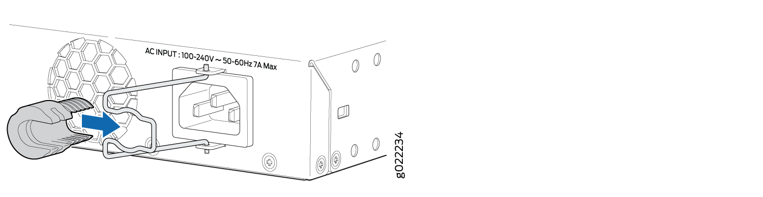
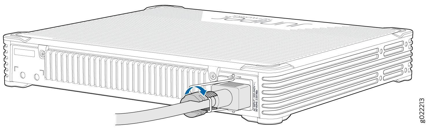
The power supply in an EX2300 switch is installed on the rear panel.
To connect AC power to the switch:
See Also
Connecting DC Power to an EX2300 Switch
Before you begin connecting DC power to the switch, ensure that you have connected earth ground to the switch chassis.
Before you connect power to the switch, a licensed electrician must attach a cable lug to the grounding and power cables. A cable with an incorrectly attached lug can damage the switch (for example, by causing a short circuit).
To meet electromagnetic interference (EMI) requirements and to ensure proper operation, you must connect the switch to earth ground before you connect them to power. For installations that require a separate grounding conductor to the chassis, use the protective earthing terminal on the switch chassis to connect to the earth ground. For instructions on connecting earth ground, see Connect Earth Ground to an EX Series Switch.
Grounding is required for DC systems and recommended for AC systems.
Ensure that you have taken the necessary precautions to prevent electrostatic discharge (ESD) damage (see Prevention of Electrostatic Discharge Damage).
Ensure that you have the following parts and tools available:
-
DC power source cables (14 AWG) with ring lug (Molex 0190700067 or equivalent) (not provided) attached to them by a licensed electrician
-
Phillips (+) screwdriver, number 2
This procedure is applicable only to the EX2300-24T-DC model. The power supply is built-in along the rear panel in the EX2300-24T-DC model.
DC-powered switches are intended for installation only in a restricted-access location.
To connect DC power to the switch:
-
Install heat-shrink tubing insulation around the power cables.
To install heat-shrink tubing:
-
Slide the tubing over the portion of the cable where it is attached to the lug barrel. Ensure that tubing covers the end of the wire and the barrel of the lug attached to it.
-
Shrink the tubing with a heat gun. Ensure that you heat all sides of the tubing evenly so that it shrinks around the cable tightly.
Figure 7 shows the steps to install heat-shrink tubing.
Note:Do not overheat the tubing.
Figure 7: How to Install Heat-Shrink Tubing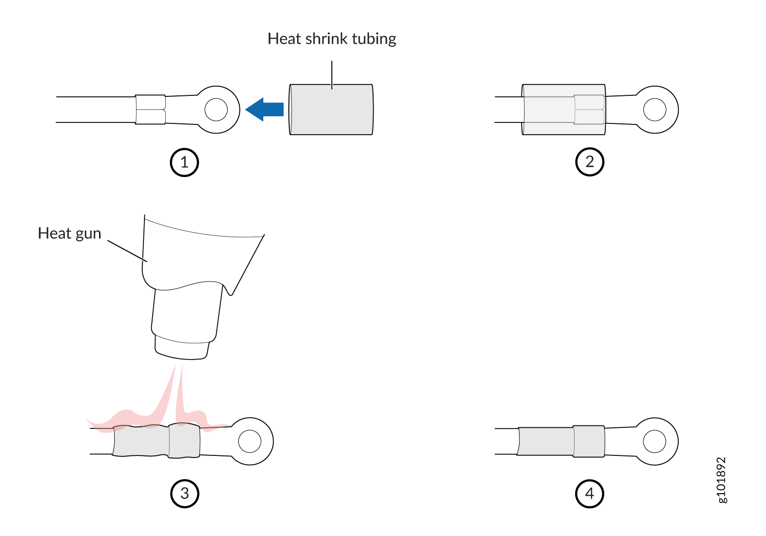
-
-
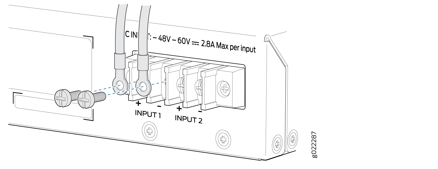
Connect the power supply to the power sources. Secure
power source cables to the power supply by screwing the ring lugs
attached to the cables to the appropriate terminals by using the screw
from the terminals (see Figure 8).
Figure 8: Securing the Ring Lugs On the Power Cables to the Terminals on the DC Power Supply
-
To connect the power supply to one power source:
-
Secure the ring lug of the positive (+) DC power source cable to the INPUT 1+ or INPUT 2+ terminal on the DC power supply.
-
Secure the ring lug of the negative (–) DC power source cable to the INPUT 1– or INPUT 2– terminal on the DC power supply.
-
Tighten the screws on the power supply terminals until snug by using the screwdriver. Do not overtighten—apply between 8 lb-in. (0.9 Nm) and 9 lb-in. (1.02 Nm) of torque to the screws.
-
-
To connect the power supply to two power sources:
-
Secure the ring lug of the positive (+) DC power source cable from the first DC power source to the INPUT 1+ terminal on the power supply.
-
Secure the ring lug of the negative (–) DC power source cable from the first DC power source to the INPUT 1– terminal on the power supply.
-
Secure the ring lug of the positive (+) DC power source cable from the second DC power source to the INPUT 2+ terminal on the power supply.
-
Secure the ring lug of the negative (–) DC power source cable from the second DC power source to the INPUT 2– terminal on the power supply.
-
Tighten the screws on the power supply terminals on both the power supplies until snug by using the screwdriver. Do not overtighten—apply between 8 lb-in. (0.9 Nm) and 9 lb-in. (1.02 Nm) of torque to the screws.
-
-