Returning an EX4300 Chassis or Components
Returning an EX4300 Switch or Component for Repair or Replacement
If you need to return an EX4300 switch or hardware component to Juniper Networks for repair or replacement, follow this procedure:
For more information about return and repair policies, see the customer support page at https://www.juniper.net/support/guidelines.html .
Locating the Serial Number on an EX4300 Switch or Component
If you are returning a switch or hardware component to Juniper Networks for repair or replacement, you must locate the serial number of the switch or component. You must provide the serial number to the Juniper Networks Technical Assistance Center (JTAC) when you contact them to obtain Return Materials Authorization (RMA).
If the switch is operational and you can access the CLI, you can list serial numbers for the switch and for some components with a CLI command. If you do not have access to the CLI or if the serial number for the component does not appear in the command output, you can locate the serial number ID label on the physical switch or component.
If you want to find the serial number on the physical switch component, you will need to remove the component from the switch chassis, for which you must have the required parts and tools available. See Installing and Removing EX4300 Switch Hardware Components.
- Listing the Switch and Components Details with the CLI
- Locating the Chassis Serial Number ID Label on an EX4300 Switch
- Locating the Serial Number ID Labels on FRUs in an EX4300 Switch
Listing the Switch and Components Details with the CLI
To list the switch and switch components and their serial numbers, enter the following CLI command:
show chassis hardware
The following output lists the switch components and serial numbers for an EX4300-48P switch:
user@switch> show chassis hardware
Hardware inventory:
Item             Version  Part number  Serial number     Description
Chassis                                PD3113060008      EX4300–48P
Routing Engine 0 REV D    650-044930   PD3113060008      EX4300-48P
FPC 0            REV D    650-044930   PD3113060008      EX4300-48P
  CPU                     BUILTIN      BUILTIN           FPC CPU
  PIC 0          REV D    BUILTIN      BUILTIN           48x 10/100/1000 Base-T
  PIC 1          REV D    BUILTIN      BUILTIN           4x 40GE
  PIC 2          REV A0   611-044925   MY3112490109      4x 1G/10G SFP/SFP+
    Xcvr 0       REV 01   740-030658   AD0946A02ZT       SFP+-10G-USR
    Xcvr 1       REV 01   740-030658   AA1212ALZ5E       SFP+-10G-USR
  Power Supply 0 REV 01   740-046871   1EDA2490663       JPSU-1100-AC-AFO-A
  Power Supply 1 REV 01   740-046873   1EDE2430149       JPSU-350-AC-AFO-A
  Fan Tray 0                                             Fan Module, Airflow Out (AFO)
  Fan Tray 1                                             Fan Module, Airflow Out (AFO)
The following output lists the switch components and serial numbers for an EX4300-48MP switch:
user@switch> show chassis hardware
Hardware inventory:
Item             Version  Part number  Serial number     Description
Chassis                                XR3617480018      EX4300-48MP
Pseudo CB 0
Routing Engine 0          BUILTIN      BUILTIN           RE-EX4300MP
FPC 0            REV 02   650-078100   XR3617480018      EX4300-48MP
  CPU                     BUILTIN      BUILTIN           FPC CPU
  PIC 0          REV 02   BUILTIN      BUILTIN           24x10M/100M/1G Base-T & 24x 100M/1G/2.5G/5G/10G Base-T
  PIC 1          REV 02   650-078100   XR3617480018      4x40G QSFP+
  PIC 2          REV      650-080740   XS3617480045      4x10G SFP+
    Xcvr 0       REV 02   740-011613   NT33F2C           SFP-SX
    Xcvr 1       REV 01   740-021308   09T511103777      SFP+-10G-SR
    Xcvr 3       REV 01   740-030658   AA1229AZXZG       SFP+-10G-USR
Power Supply 0   REV 01   740-074873   1F197410083       JPSU-1400W-AC-AFO
Fan Tray 0                                               Fan Module, Airflow Out (AFO)
Fan Tray 1                                               Fan Module, Airflow Out (AFO)
For information about the show chassis hardware command,
see show chassis hardware.
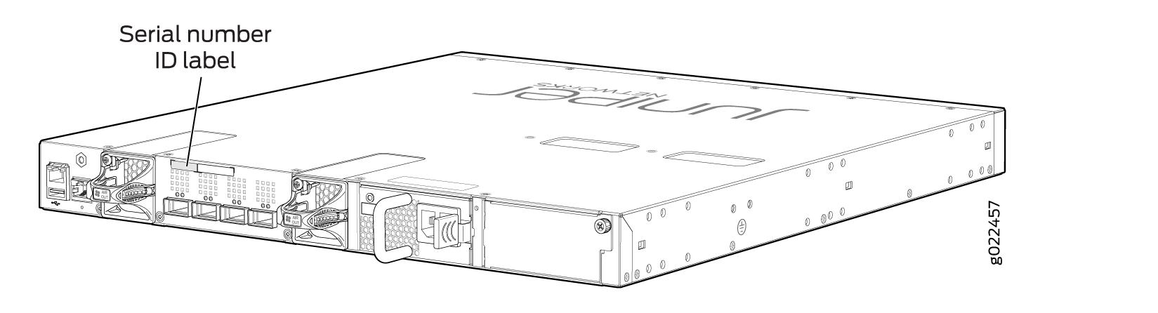
Locating the Chassis Serial Number ID Label on an EX4300 Switch
The serial number ID label is located on the rear panel of the chassis on EX4300 switches. Figure 1 shows the location of the serial number ID label on 24-port and 48-port EX4300 switches except EX4300-48MP and EX4300-48MP-S switches. Figure 2 shows the location of the serial number ID label on EX4300-48MP and EX4300-48MP-S switches. Figure 3 shows the location of the serial number ID label on 32-port EX4300 switches.
Locating the Serial Number ID Labels on FRUs in an EX4300 Switch
The power supplies, fan modules, and uplink modules, installed in EX4300 switches are field-replaceable units (FRUs).
For each of these FRUs, you must remove the FRU from the switch chassis to see the FRU’s serial number ID label.
-
Power Supply—The serial number ID label is on the top of the power supply. Figure 4 shows the location of the serial number ID label on an AC power supply used in EX4300 switches except EX4300-48MP and EX4300-48MP-S switches, Figure 5 shows the location of the serial number ID label on an AC power supply used in EX4300-48MP and EX4300-48MP-S switches, and Figure 6 shows the location of the serial number ID label on a DC power supply. EX4300-48MP and EX4300-48MP-S switches do not support DC power supply. SeeRemoving an AC Power Supply from an EX4300 Switch and Removing an AC Power Supply from an EX4300 Switch.
Figure 4: Location of the Serial Number ID Label on an AC Power Supply Used in EX4300 Switches Except EX4300-48MP and EX4300-48MP-S Switches Figure 5: Location of the Serial Number ID Label on an AC Power Supply Used in EX4300-48MP and EX4300-48MP-S Switches
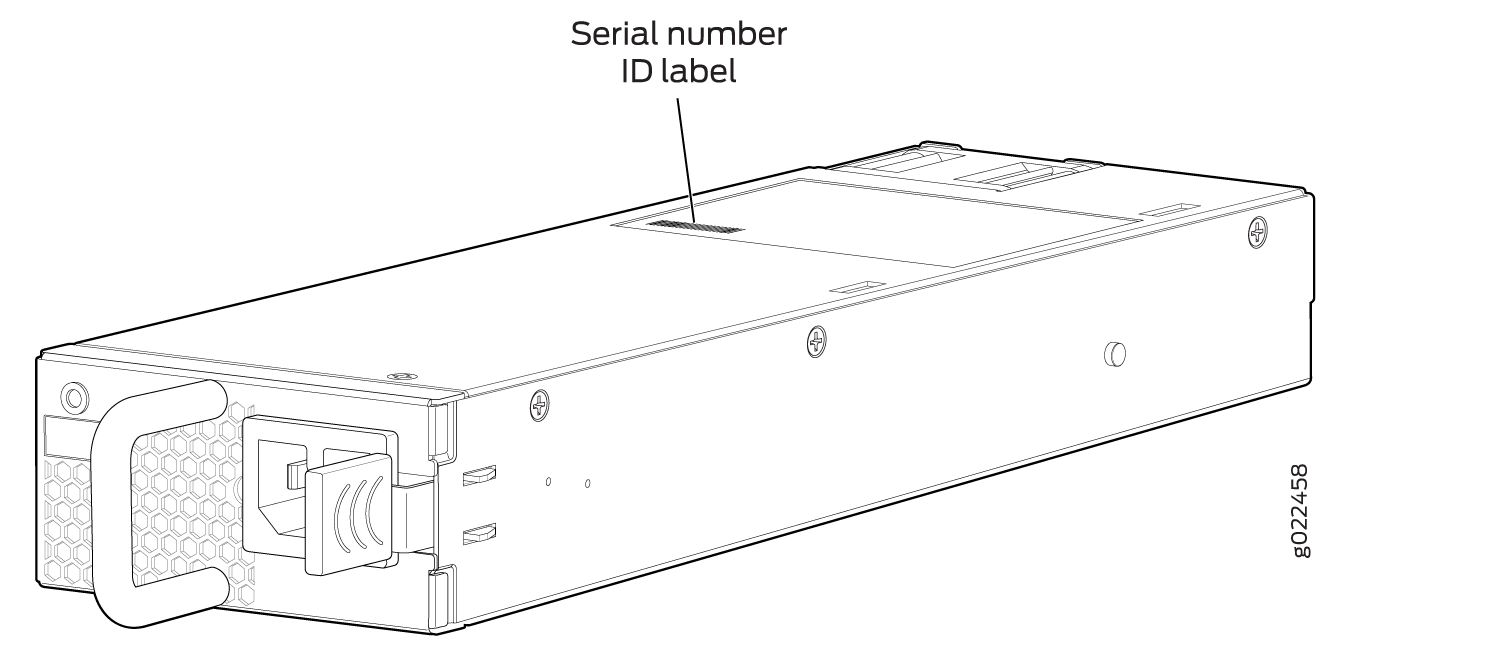 Figure 6: Location of the Serial Number ID Label on a DC Power Supply Used in EX4300 Switches
-
Fan module—Figure 7 shows the location of the serial number ID label on the fan module for EX4300 switches except EX4300-48MP and EX4300-48MP-S switches. Figure 8 shows the location of the serial number ID label on the fan module for EX4300-48MP and EX4300-48MP-S switches. See Removing a Fan Module from an EX4300 Switch.
Figure 7: Location of the Serial Number ID Label on the Fan Module Used in an EX4300 Switches Except EX4300-48MP and EX4300-48MP-S Switches Figure 8: Location of the Serial Number ID Label on the Fan Module Used in an EX4300-48MP and EX4300-48MP-S Switches
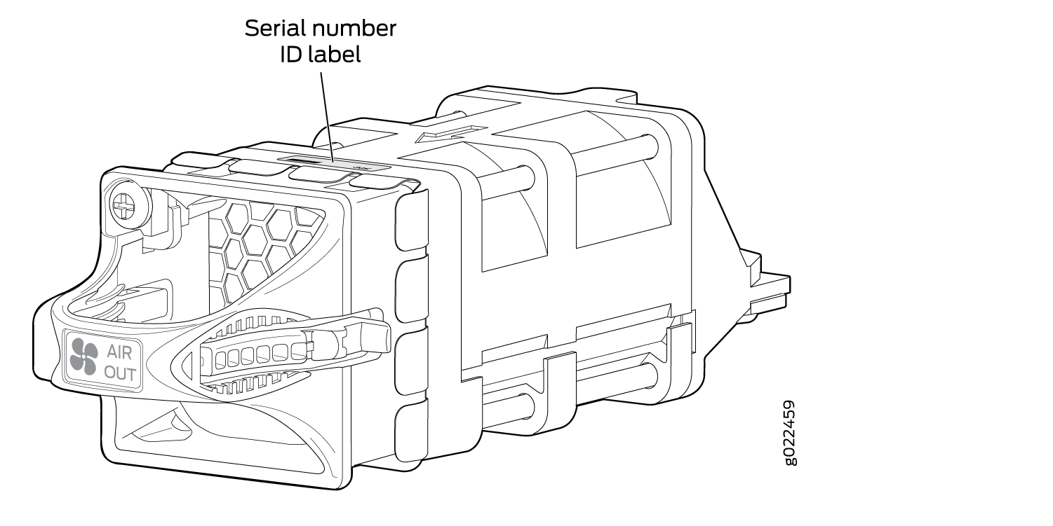
-
Uplink modules
-
EX4300 switches except EX4300-48MP and EX4300-48MP-S switches—Figure 9 shows the location of the serial number ID label on the QSFP+ uplink module, Figure 11 shows the location of the serial number ID label on the 4-port SFP+ uplink module, and Figure 12 shows the location of the serial number ID label on the 8-port SFP+ uplink module.
-
EX4300-48MP and EX4300-48MP-S switches—Figure 10 shows the location of the serial number ID label on the 2-port 40-Gigabit Ethernet QSFP+/100-Gigabit Ethernet QSFP28 uplink module (model number: EX-UM-2QSFP-MR) and Figure 13 shows the location of the serial number ID label on the 4-port 1-Gigabit Ethernet SFP/10-Gigabit Ethernet SFP+ uplink module (model number: EX-UM-4SFPP-MR) for EX4300-48MP and EX4300-48MP-S switches.
See Removing an Uplink Module from an EX4300 Switch.
Figure 9: Location of the Serial Number ID Label on the QSFP+ Uplink Module Figure 10: Location of the Serial Number ID Label on the 2-Port 40-Gigabit Ethernet QSFP+/100-Gigabit Ethernet QSFP28 Uplink Module for EX4300-48MP Switches
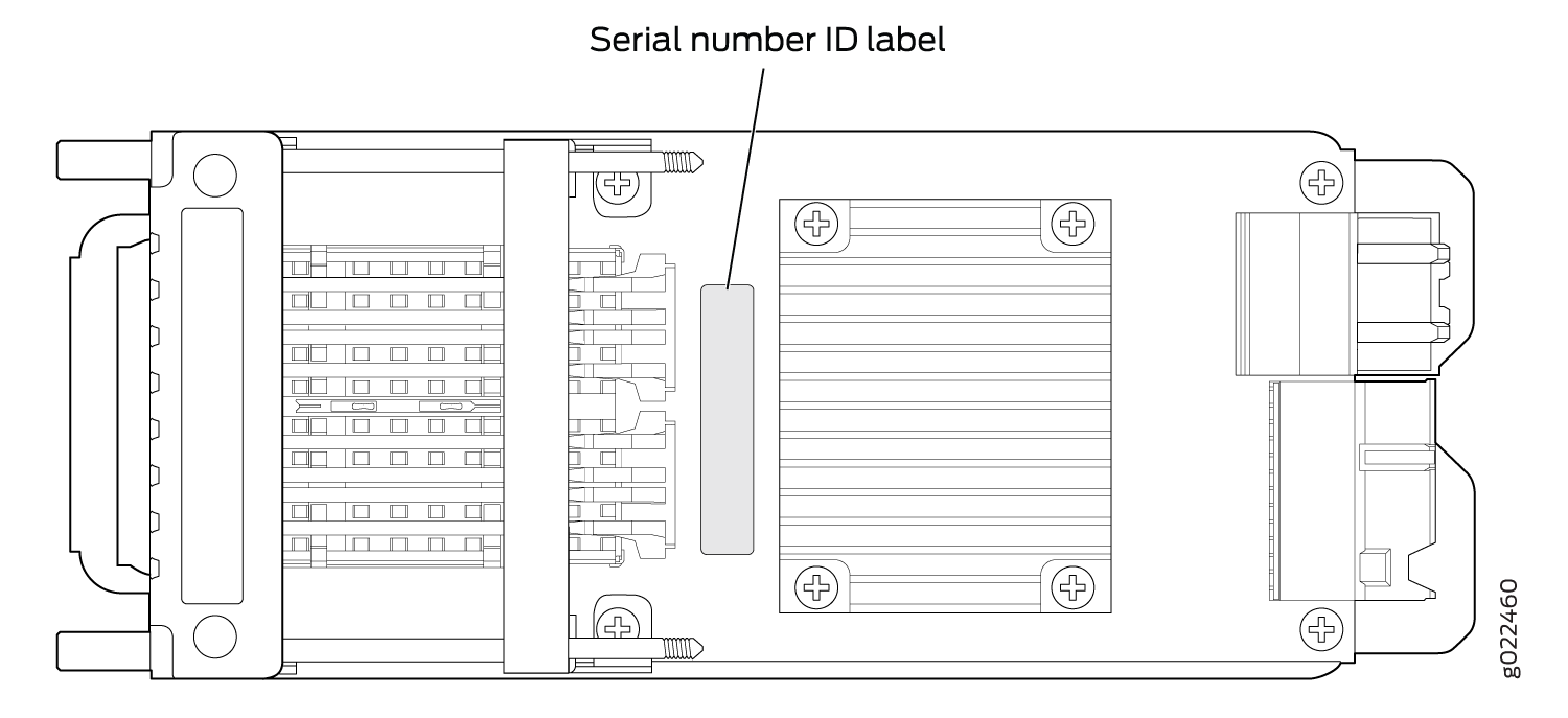 Figure 11: Location of the Serial Number ID Label on the 4-Port SFP+ Uplink Module for EX4300 Switches Except EX4300-48MP and EX4300-48MP-S Switches
 Figure 12: Location of the Serial Number ID Label on the 8-Port SFP+ Uplink Module
 Figure 13: Location of the Serial Number ID Label on the 4-Port 1-Gigabit Ethernet SFP/10-Gigabit Ethernet SFP+ Uplink Module for EX4300-48MP Switches
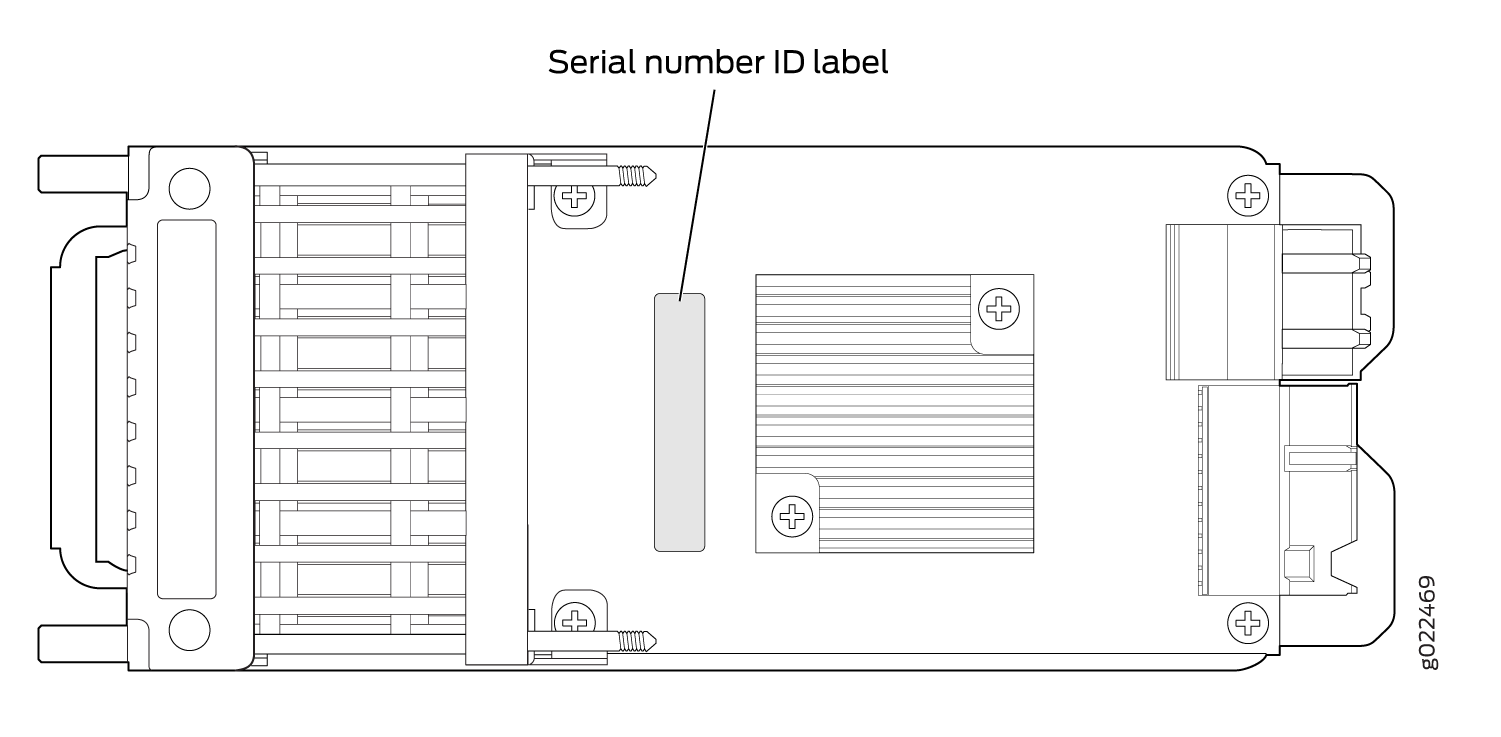
-
Contact Customer Support to Obtain a Return Material Authorization
If you need to return a device or hardware component to Juniper Networks for repair or replacement, obtain an RMA number from JTAC. You must obtain an RMA number before you attempt to return the component.
After locating the serial number of the device or hardware component you want to return, open a service request with the JTAC on the Web or by telephone.
Before you request an RMA number from JTAC, be prepared to provide the following information:
-
Your existing service request number, if you have one
-
Serial number of the component
-
Your name, organization name, telephone number, fax number, and shipping address
-
Details of the failure or problem
-
Type of activity being performed on the device when the problem occurred
-
Configuration data displayed by one or more
showcommands
You can contact JTAC 24 hours a day, seven days a week, on the Web or by telephone:
-
Service Request Manager: https://support.juniper.net/support
-
Telephone: +1-888-314-JTAC (+1-888-314-5822), toll free in U.S., Canada, and Mexico
For international or direct-dial options in countries without toll free numbers, see https://support.juniper.net/support.
If you are contacting JTAC by telephone, enter your 12-digit service request number followed by the pound (#) key for an existing case, or press the star (*) key to be routed to the next available support engineer.
The support representative validates your request and issues an RMA number for return of the component.
Packing an EX4300 Switch or Component for Shipping
If you are returning an EX4300 switch or component to Juniper Networks for repair or replacement, pack the item as described in this topic.
Before you begin packing the switch or component, ensure you have:
Followed all the steps listed in Contact Customer Support to Obtain Return Material Authorization.
Retrieved the original shipping carton and packing materials. Contact your JTAC representative if you do not have these materials, to learn about approved packing materials. See Contact Customer Support to Obtain Return Material Authorization.
Ensure you understand how to prevent electrostatic discharge (ESD) damage. See Prevention of Electrostatic Discharge Damage.
This topic describes:
Packing an EX4300 Switch for Shipping
Before you pack the switch:
On the console or other management device connected to the switch, enter the CLI operational mode and issue the following command to shut down the switch software:
user@switch> request system halt
Wait until a message appears on the console confirming that the operating system has halted.
Disconnect power from the switch by performing one of the following:
If the power source outlet has a power switch, set it to the OFF (0) position.
If the power source outlet does not have a power switch, gently pull out the plug end of the power cord connected to the power source outlet.
Remove the cables that connect the switch to all external devices. See Disconnect a Fiber-Optic Cable.
Remove all optical transceivers installed in the switch. See Remove a Transceiver.
If you need to transport the switch to another location or return the switch to Juniper Networks, you need to pack the switch securely in its original packaging to prevent damage during transportation.
Ensure that you have the following parts and tools available to pack the switch:
Phillips (+) screwdriver, number 2
The original switch packing material (cardboard box, accessory box and its contents, and foam padding)
ESD grounding strap
Antistatic bag
Do not pack the switch in anything except its original container or the switch might be damaged in transit.
To pack the switch:
- If the switch is installed in a rack or cabinet, have one person support the weight of the switch while another person unscrews and removes the mounting screws.
- Remove the switch from the rack or cabinet and place the switch on a flat, stable surface.
- Use the screwdriver to remove the rack-mounting brackets from the switch chassis.
- Place the switch in an antistatic bag.
- Place the bottom portion of the packaging foam in the shipping carton.
- Place the switch inside the cavity in the bottom packaging foam.
- Place the top portion of the packaging foam on top of the switch.
- If you are returning accessories or field-replaceable units (FRUs) with the switch, pack them as instructed in Packing EX4300 Switch Components for Shipping.
- Place the accessory box vertically by the rear end of the chassis in the shipping carton.
- Close the top of the cardboard shipping box and seal it with packing tape.
- Write the RMA number on the exterior of the box to ensure proper tracking.
Packing EX4300 Switch Components for Shipping
Ensure that you have the following parts and tools available:
Antistatic bag, one for each component
ESD grounding strap
To pack the switch components, follow the instructions here.
Do not stack switch components. Return individual components in separate boxes if they do not fit together on one level in the shipping box.
To pack the switch components:
Place individual components in antistatic bags.
Use the original packing materials if they are available. If the original packing materials are not available, ensure the component is adequately packed to prevent damage during transit. The packing material you use must be able to support the weight of the component.
Ensure that the components are adequately protected by wrapping them well with packing materials. Pack the component in an oversized box (if the original box is not available) with extra packing material around the unit so that the component is prevented from moving around inside the box.
Securely tape the box closed.
Write the RMA number on the exterior of the box to ensure proper tracking.