Unpacking and Mounting the EX4300 Switch
Unpacking an EX4300 Switch
EX4300 switches are shipped in a cardboard carton, secured with foam packing material. The carton has an accessory compartment.
EX4300 switches are maximally protected inside the shipping carton. Do not unpack the switches until you are ready to begin installation.
To unpack the switch:
- Move the shipping carton to a staging area as close to the installation site as possible, but where you have enough room to remove the system components.
- Position the carton so that the arrows are pointing up.
- Open the top flaps on the shipping carton.
- Pull out the packing material holding the switch in place.
- Verify the parts received against the inventory on the label attached to the carton. See Parts Inventory (Packing List) for an EX4300 Switch.
- Save the shipping carton and packing materials in case you need to move or ship the switch later.
Parts Inventory (Packing List) for an EX4300 Switch
The switch shipment includes a packing list. Check the parts you receive with the switch against the items on the packing list. The packing list specifies the part number and provides a description of each part in your order. The parts shipped depend on the switch model you order. See EX4300 Switch Models for more information.
If any part on the packing list is missing, contact your customer service representative or contact Juniper customer care from within the U.S. or Canada by telephone at 1-888-314-5822. For international-dial or direct-dial options in countries without toll-free numbers, see https://www.juniper.net/support/requesting-support.html .
Table 1 lists the parts and their quantities as in the standard packing list for an EX4300 switch.
Component |
Quantity |
|
|---|---|---|
Switch |
1 |
|
Fan modules |
EX4300-24T, EX4300-24P, EX4300-32F, EX4300-48T, EX4300-48T-AFI, EX4300-48P, EX4300-48MP, EX4300-48T-DC, and EX4300-48T-DC-AFI switches |
2 preinstalled |
EX4300-24T-S, EX4300-24P-S, EX4300-32F-S, EX4300-48T-S, EX4300-48P-S, and EX4300-48MP-S switches |
Fan modules for this model are not shipped by default; you must order two fan modules separately. |
|
Power supplies |
EX4300-24T, EX4300-24P, EX4300-32F, EX4300-48T, EX4300-48T-AFI, EX4300-48P, EX4300-48MP, EX4300-48T-DC, and EX4300-48T-DC-AFI switches |
1 (AC or DC) preinstalled |
EX4300-24T-S, EX4300-24P-S, EX4300-32F-S, EX4300-48T-S, EX4300-48P-S, and EX4300-48MP-S switches |
Power supplies for this model are not shipped by default; you must order power supplies separately. |
|
AC power cord appropriate for your geographical location |
EX4300-24T, EX4300-24P, EX4300-32F, EX4300-48T, EX4300-48T-AFI, EX4300-48P, and EX4300-48MP switches |
1 |
EX4300-24T-S, EX4300-24P-S, EX4300-32F-S, EX4300-48T-S, EX4300-48P-S, and EX4300-48MP-S switches |
AC power cord for these models is not shipped by default; you must order it separately. |
|
AC power cord retainer |
EX4300-24T, EX4300-24P, EX4300-32F, EX4300-48T, EX4300-48T-AFI, EX4300-48P, and EX4300-48MP switches |
1 |
EX4300-24T-S, EX4300-24P-S, EX4300-32F-S, EX4300-48T-S, EX4300-48P-S, and EX4300-48MP-S switches |
AC power cord retainer for these models is not shipped by default; a retainer is shipped if you order an AC power supply. |
|
Cover panels for slots without preinstalled components |
|
|
Mounting brackets |
2 |
|
Mounting screws |
8 |
|
Rubber feet |
4 |
|
Documentation Roadmap |
1 |
|
Juniper Networks Product Warranty |
1 |
|
End User License Agreement |
1 |
|
Do not mix:
AC and DC power supplies in the same chassis
Power supplies with different airflow labels (AIR IN (AFI) and AIR OUT (AFO)) in the same chassis.
Fan modules with different airflow labels (AIR IN (AFI) and AIR OUT (AFO)) in the same chassis.
Power supplies and fan modules with different airflow labels (AIR IN (AFI) and AIR OUT (AFO)) in the same chassis.
You must provide the appropriate mounting screws for mounting the switch on a rack or a cabinet.
Update Base Installation Data
Update the installation base data if any addition or change to the installation base occurs or if the installation base is moved. Juniper Networks is not responsible for not meeting the hardware replacement SLA for products that do not have accurate installation base data.
Update your installation base at https://supportportal.juniper.net/s/CreateCase .
Installing and Connecting an EX4300 Switch
To install and connect an EX4300 switch:
See Also
Mounting an EX4300 Switch
You can mount an EX4300 switch:
On two posts of a 19-in. rack or a 19-in. cabinet by using the mounting brackets provided with the switch.
On four posts of a 19-in. rack or a 19-in. cabinet by using the separately orderable four-post rack-mount kit.
In a position recessed 2 in. from the front of a 19-in. rack or a 19-in. cabinet by using the 2-in.-recess front brackets in the separately orderable four-post rack-mount kit. You can mount the switch in this recessed position on two-post or four-post racks and cabinets.
On a wall by using the separately orderable wall-mount kit.
The holes in the mounting brackets are placed at 1 U (1.75 in. or 4.45 cm) apart so that the switch can be mounted in any rack or cabinet that provides holes spaced at that distance.
See the Related Documentation for detailed descriptions of the various rack or cabinet mounting options.
See Also
Mounting an EX4300 Switch on Two Posts of a Rack or Cabinet
Before mounting the switch on two posts of a rack:
Verify that the site meets the requirements described in Site Preparation Checklist for EX4300 Switches.
Place the rack in its permanent location, allowing adequate clearance for airflow and maintenance, and secure it to the building structure.
Read General Safety Guidelines and Warnings, with particular attention to Chassis and Component Lifting Guidelines.
Remove the switch from the shipping carton (see Unpacking an EX4300 Switch).
Ensure that you have the following parts and tools available:
Phillips (+) screwdriver, number 2 (not provided)
2 mounting brackets and 8 mounting screws (provided in the accessory box shipped with the switch)
Screws to secure the chassis to the rack (not provided)
2-in.-recess front-mounting brackets if you will mount the switch in a recessed position (part of the separately orderable four-post rack-mount kit)
Cover panels for uplink module and power supply slots (provided)
You can mount an EX4300 switch on two posts of a 19-in. rack (either a two-post or a four-post rack) or a 19-in. cabinet by using the mounting brackets provided with the switch. (The remainder of this topic uses rack to mean rack or cabinet.)
You can mount the switch on four posts of a four-post rack by using the mounting brackets provided with the separately orderable four-post rack-mount kit. See Mounting an EX4300 Switch on Four Posts of a Rack or Cabinet.
If you need to mount the switch in a recessed position on two posts of either a two-post rack or a four-post rack, you can use the 2-in.-recess front-mounting brackets provided in the separately orderable four-post rack-mount kit.
One person must be available to lift the switch while another secures the switch to the rack.
If you are mounting multiple switches on a rack, mount a switch in the bottom of the rack first and proceed to mount the rest of the switches from bottom to top.
To mount the switch on two posts of a rack:
- Align the mounting brackets along the front, rear, or
center of the side panels of the switch chassis depending on how you
want to mount the switch. For example, if you want to front-mount
EX4300 switches except EX4300-48MP and EX4300-48MP-S switches, align
the brackets along the front of the side panel (see Figure 1). If you want
to front-mount an EX4300-48MP or EX4300-48MP-S switch, align the brackets
17.5 mm offset from the front panel (see Figure 2 and Figure 3).Figure 1: Attaching the Mounting Bracket to the Side Panel of EX4300 Switches Except EX4300-48MP and EX4300-48MP-S Switches
 Figure 2: Attaching the Mounting Bracket to the Side Panel of EX4300-48MP and EX4300-48MP-S Switches
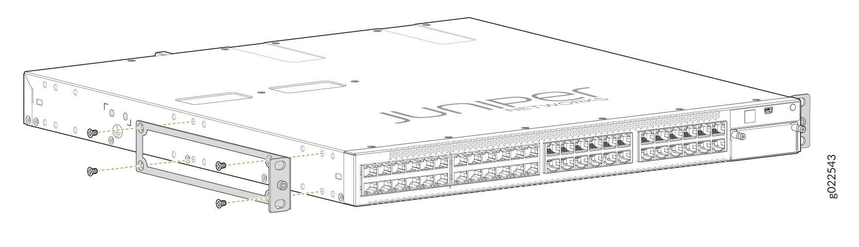 Figure 3: Mounting Bracket Attached to the Side Panel of EX4300-48MP and EX4300-48MP-S Switches
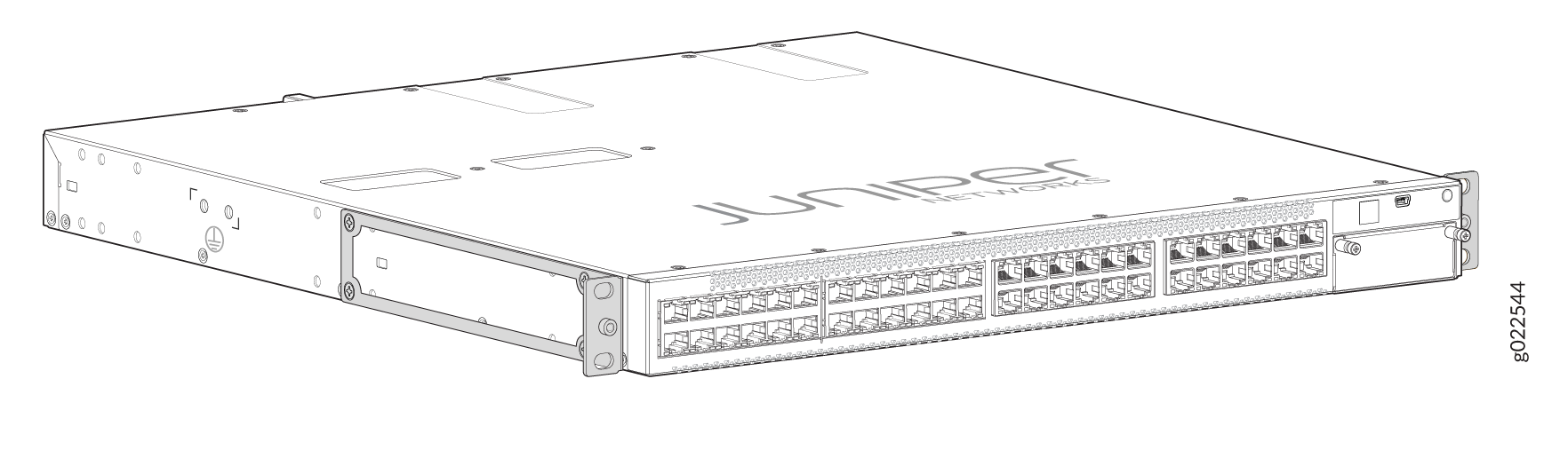
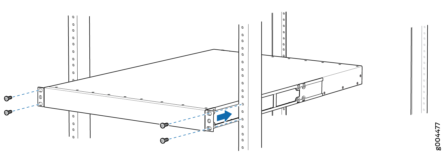
- Have one person grasp both sides of the switch, lift the
switch, and position it in the rack, aligning the mounting bracket
holes with the threaded holes in the rack or cabinet rail. Align the
bottom hole in both the mounting brackets with a hole in each rack
rail, making sure the chassis is level. See Figure 4.Figure 4: Mounting the Switch on Two Posts of a Rack
We recommend that you install cover panels in the unused uplink module and power supply slots.
See Also
Mounting an EX4300 Switch on Four Posts of a Rack or Cabinet
Before mounting the switch on four posts of a rack:
-
Verify that the site meets the requirements described in Site Preparation Checklist for EX4300 Switches.
-
Place the rack in its permanent location, allowing adequate clearance for airflow and maintenance, and secure it to the building structure.
-
Read General Safety Guidelines and Warnings, with particular attention to Chassis and Component Lifting Guidelines.
-
Remove the switch from the shipping carton (see Unpacking an EX4300 Switch).
Ensure that you have the following parts and tools available:
-
Phillips (+) screwdriver, number 2 (not provided)
-
6 flat-head 4-40 Phillips mounting screws (provided with the four-post rack-mount kit)
-
12 flat-head 4x6-mm Phillips mounting screws (provided with the four-post rack-mount kit)
-
One pair each of flush or 2-in.-recess front-mounting brackets (provided with the four-post rack-mount kit)
-
One pair of side mounting-rails (provided with the four-post rack-mount kit)
-
One pair of rear mounting-blades (provided with the four-post rack-mount kit)
-
Screws to secure the chassis and the rear mounting-blades to the rack (not provided)
-
Cover panels for uplink module and power supply slots (provided)
You can mount an EX4300 switch on four posts of a 19-in. rack or a 19-in. cabinet by using the separately orderable four-post rack-mount kit. (The remainder of this topic uses rack to mean rack or cabinet.)
You can mount the switch on two posts of either a two-post rack or a four-post rack by using the mounting brackets provided with the switch. See Mounting an EX4300 Switch on Two Posts of a Rack or Cabinet.
If you need to mount the switch in a recessed position on either a two-post rack or a four-post rack, you can use the 2-in.-recess front-mounting brackets provided in the separately orderable four-post rack-mount kit.
To ensure that the protective earthing terminal is accessible through the opening in the rear mounting-blade:
-
Ensure that the rack is 27.5 in. (70 cm) through 30.5 in. (77.5 cm) deep if you are mounting the switch flush with the rack front on four posts of a rack.
-
Ensure that the rack is 29.5 in. (75 cm) through 32.5 in. (82.5 cm) deep if you will mount the switch 2 in. recessed from the rack front.
One person must be available to lift the switch while another secures it to the rack.
If you are mounting multiple units on a rack, mount the heaviest unit at the bottom of the rack and mount the other units from the bottom of the rack to the top in decreasing order of the weight of the units.
To mount the switch on four posts of a rack:
-
Insert 4x6-mm Phillips flat-head mounting screws into
the two aligned holes and tighten the screws by using the screwdriver.
Ensure that the remaining four holes in the side mounting-rails are
aligned with the four holes in the side panel. See Figure 5.
Figure 5: Attaching the Side Mounting-Rail to the Switch Chassis
-
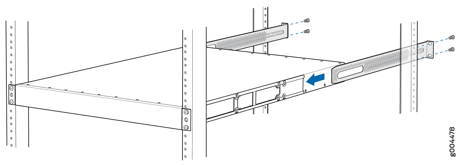
Have one person grasp both sides of the switch, lift the
switch, and position it in the rack, aligning the side mounting-rail
holes with the threaded holes in the front post of the rack. Align
the bottom hole in both the front-mounting brackets with a hole in
each rack rail, making sure the chassis is level. See Figure 6.
Figure 6: Mounting the Switch on Front Posts of a Rack
-
Slide the rear mounting-blades into the side mounting-rails.
See Figure 7.
Figure 7: Sliding the Rear Mounting-Blades into the Side Mounting-Rails
We recommend that you install cover panels in the unused uplink module and power supply slots.
See Also
Mounting an EX4300 Switch in a Recessed Position in a Rack or Cabinet
You can mount an EX4300 switch in a recessed position on two posts of either a two-post rack or a four-post rack such that the switch is recessed inside the rack from the rack front by 2 inches. To mount the switch in a recessed position, use the front-mounting brackets provided in the separately orderable four-post rack-mount kit.
Reasons to mount the switch in a recessed position include:
You are mounting the switch in a cabinet and the cabinet doors do not close completely unless the switch is recessed.
The switch you are mounting has an uplink module with transceivers installed in it—the transceivers in the uplink module ports protrude from the front of the switch.
To mount the switch in a recessed position, on two-posts or on four-posts, follow the instructions in Mounting an EX4300 Switch on Two Posts of a Rack or Cabinet or Mounting an EX4300 Switch on Four Posts of a Rack or Cabinet.
See Also
Mounting an EX4300 Switch on a Wall
Before mounting the switch on a wall:
-
Verify that the site meets the requirements described in Site Preparation Checklist for EX4300 Switches.
-
Read General Safety Guidelines and Warnings, with particular attention to Chassis and Component Lifting Guidelines.
-
Remove the switch from the shipping carton (see Unpacking an EX4300 Switch).
Ensure that you have the following parts and tools available:
-
Phillips (+) screwdriver, number 2 (not provided)
-
2 wall-mount brackets (provided with the wall-mount kit)
-
12 wall-mount bracket screws (provided with the wall-mount kit)
-
4 mounting screws (8-32 x 1.25 in. or M4 x 30 mm) (not provided)
-
Cover panels for uplink module and power supply slots (provided)
-
Hollow wall anchors capable of supporting the combined weight of two fully loaded switches, up to 33 lb (15 kg) (not included)—if you are mounting the switch in sheetrock (wall board with a gypsum plaster core) or in wall board not backed by wall studs.
When mounting EX4300 switches except EX4300-48MP and EX4300-48MP-S switches on a wall, orient the front panel of the chassis downward to ensure proper airflow and meet safety requirements in the event of a fire. When mounting EX4300-48MP and EX4300-48MP-S switches on a wall, orient the front panel of the chassis pointing to the right side or to the left side to ensure proper airflow and meet safety requirements in the event of a fire.
For easier lifting, install any additional power supplies only after you mount the switch on the wall.
You can mount an EX4300 switch on a wall by using the separately orderable wall-mount kit.
To mount the switch on a wall:
-
Attach the wall-mount brackets to the sides of the chassis
by using four of the wall-mount bracket screws on each side (see the
representation in Figure 8). Use the screwdriver to tighten the screws.
Figure 8: Attaching Wall-Mount Brackets to the Switch Chassis
-
Grasp each side of the switch or switches, lift the switch
or switches, and hang the brackets from the mounting screws (see the
representation in Figure 9).
Figure 9: Mounting the Switch on a Wall
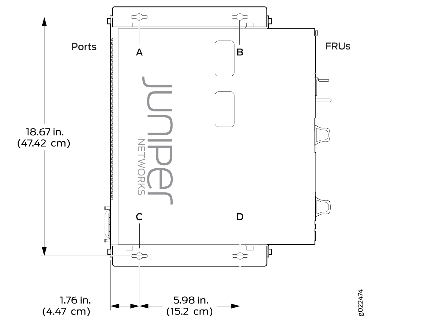
 Figure 10: Measurements for Mounting EX4300-48MP and EX4300-48MP-S Switches on a Wall with the Front Panel Pointing to the Right Side
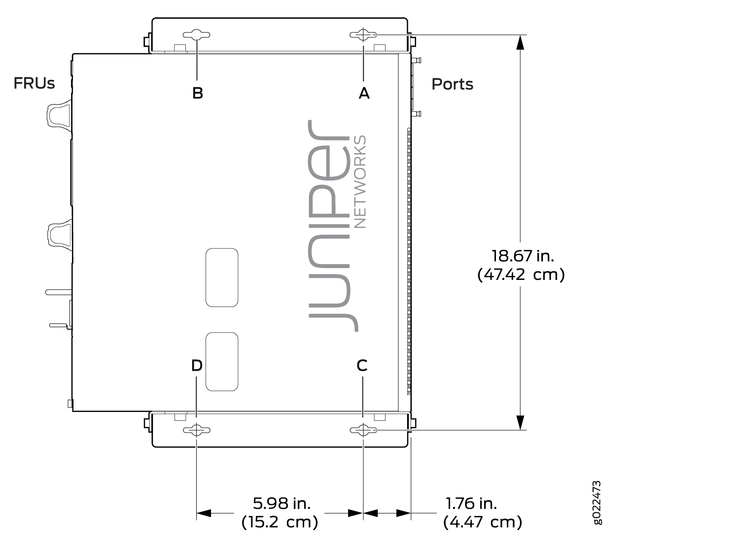 Figure 11: Mounting EX4300-48MP and EX4300-48MP-S Switches on a Wall with the Front Panel Pointing to the Left Side