Unpacking and Mounting the EX2300 Switch
Unpacking an EX2300 Switch
EX2300 switches are shipped in a cardboard carton, secured with foam packing material. The carton also contains an accessory box.
EX2300 switches are maximally protected inside the shipping carton. Do not unpack the switches until you are ready to begin installation.
To unpack the switch:
- Move the shipping carton to a staging area as close to the installation site as possible, but where you have enough room to remove the system components.
- Position the carton so that the arrows point up.
- Open the top flaps on the shipping carton.
- Remove the accessory box and verify the contents in it against the parts inventory on the label attached to the carton.
- Pull out the packing material holding the switch in place.
- Verify the chassis components received against the packing list included with the switch. An inventory of parts provided with the switch is provided in Parts Inventory (Packing List) for an EX2300 Switch.
- Save the shipping carton and packing materials in case you need to move or ship the switch later.
Parts Inventory (Packing List) for an EX2300 Switch
EX2300 switches are shipped in a cardboard carton, secured with foam packing material. The carton also contains an accessory box.
The switch shipment includes a packing list. Check the parts you receive in the switch shipping carton against the items on the packing list. The parts shipped depend on the configuration you order.
If any part on the packing list is missing, contact your customer service representative or contact Juniper customer care from within the U.S. or Canada by telephone at 1-888-314-5822. For international-dial or direct-dial options in countries without toll-free numbers, see https://www.juniper.net/support/requesting-support.html.
Table 1 lists the parts and their quantities in the packing list.
Component |
Quantity |
|---|---|
Switch with built-in power supply |
1 |
AC power cord appropriate for your geographical location (only for AC switch models) |
1 |
Power cord retainer clip (only for AC switch models except the EX2300-24MP model and the EX2300-48MP model) |
1 |
Mounting brackets:
|
2 |
Mounting screws to attach the mounting brackets to the switch chassis:
|
8 |
Rubber feet (preinstalled on the chassis) |
4 |
Documentation Roadmap |
1 |
Paper license for Virtual Chassis (only for the models EX2300-C-12T-VC, EX2300-C-12P-VC, EX2300-24T-VC, EX2300-24P-VC, EX2300-48T-VC, EX2300-48P-VC, EX2300-48MP-VC, and EX2300-24MP-VC) |
1 |
Juniper Networks Product Warranty |
1 |
End User License Agreement |
1 |
You must provide mounting screws that are appropriate for your rack or cabinet to mount the switch on a rack or a cabinet.
Update Base Installation Data
Update the installation base data if any addition or change to the installation base occurs or if the installation base is moved. Juniper Networks is not responsible for not meeting the hardware replacement SLA for products that do not have accurate installation base data.
Update your installation base at https://supportportal.juniper.net/s/CreateCase .
Installing and Connecting an EX2300 Switch
To install and connect an EX2300 switch:
See Also
Mounting an EX2300 Switch
Table 2 lists the methods you can use to mount an EX2300 switch.
Mounting Method |
Switch Model |
More Information |
|---|---|---|
Desk or other level surface (using the rubber feet preinstalled on the chassis) |
|
On a desk or other level surface by using the rubber feet preinstalled on the chassis |
Desk or other level surface (using screws) |
EX2300-C |
On or under a desk or other level surface by using screws |
Wall |
EX2300-C |
On a wall by using screws |
EX2300 except the EX2300-24MP and EX2300-48MP models |
On a wall by using the separately orderable wall-mount kit |
|
A surface made of ferrous material |
EX2300-C |
On or under a surface made of ferrous material by using the separately orderable magnet-mount kit |
Two-post rack or cabinet |
|
On two posts in a 19-in. rack or cabinet by using the mounting brackets (separately orderable for EX2300-C switches and provided for EX2300 switches) |
Four-post rack or cabinet |
EX2300-C |
On two posts in a 19-in. rack-mounting brackets or cabinet by using the separately orderable two-post rack-mounting brackets |
EX2300 |
On four posts in a 19-in. rack-mounting brackets or cabinet by using the separately orderable four-post rack-mount kit |
|
Recessed position |
EX2300 |
In a position recessed 2 in. from the front of a 19-in. rack or cabinet by using the 2-in.-recess front-mounting brackets in the separately orderable four-post rack-mount kit. You can mount the switch in this recessed position on two-post or four-post racks and cabinets. |
The holes in the mounting brackets are placed 1 U (1.75 in. or 4.45 cm) apart so that the switch can be mounted in any rack or cabinet that provides holes spaced at that distance.
Mounting an EX2300 Switch on a Desk or Other Level Surface
Before mounting the switch on a desk or other level surface:
-
Verify that the site meets the requirements described in Site Preparation Checklist for EX2300 Switches.
-
Place the desk in its permanent location, allowing adequate clearance for airflow and maintenance, and secure it to the building structure.
-
Read General Safety Guidelines and Warnings, with particular attention to Chassis and Component Lifting Guidelines.
Do not block the vents on the top of EX2300-C switches. Blocking the vents can lead to overheating of the switch chassis.
Ensure that you have the following parts and tools available:
-
(Optional and separately orderable; applies only to EX2300-C switches) 1 cable guard kit. The kit includes the cable guard and 3 number-8 Phillips truss-head screws to secure the cable guard to the EX2300-C switch
-
(Optional and separately orderable; applies only to EX2300-C switches) 1 standard cable lock kit to secure the EX2300-C switch from theft by connecting the cable to the security slot on the switch and a desk or a rack to fasten the cable lock. The kit includes the standard cable lock and its key.
You can mount an EX2300 switch on a desk or other level surface by using the four rubber feet that are preinstalled on the switch. The rubber feet stabilize the chassis.
To mount a switch on a desk or other level surface:
- Remove the switch from the shipping carton (see Unpacking an EX2300 Switch).
-
(Optional; applies only to EX2300-C switches) Attach the
cable guard to protect cable connections:
-
Use the thumbscrews to tighten or loosen the cable guard
so that you can insert cables. See Figure 1.
Figure 1: Attaching a Cable Guard to an EX2300-C Switch
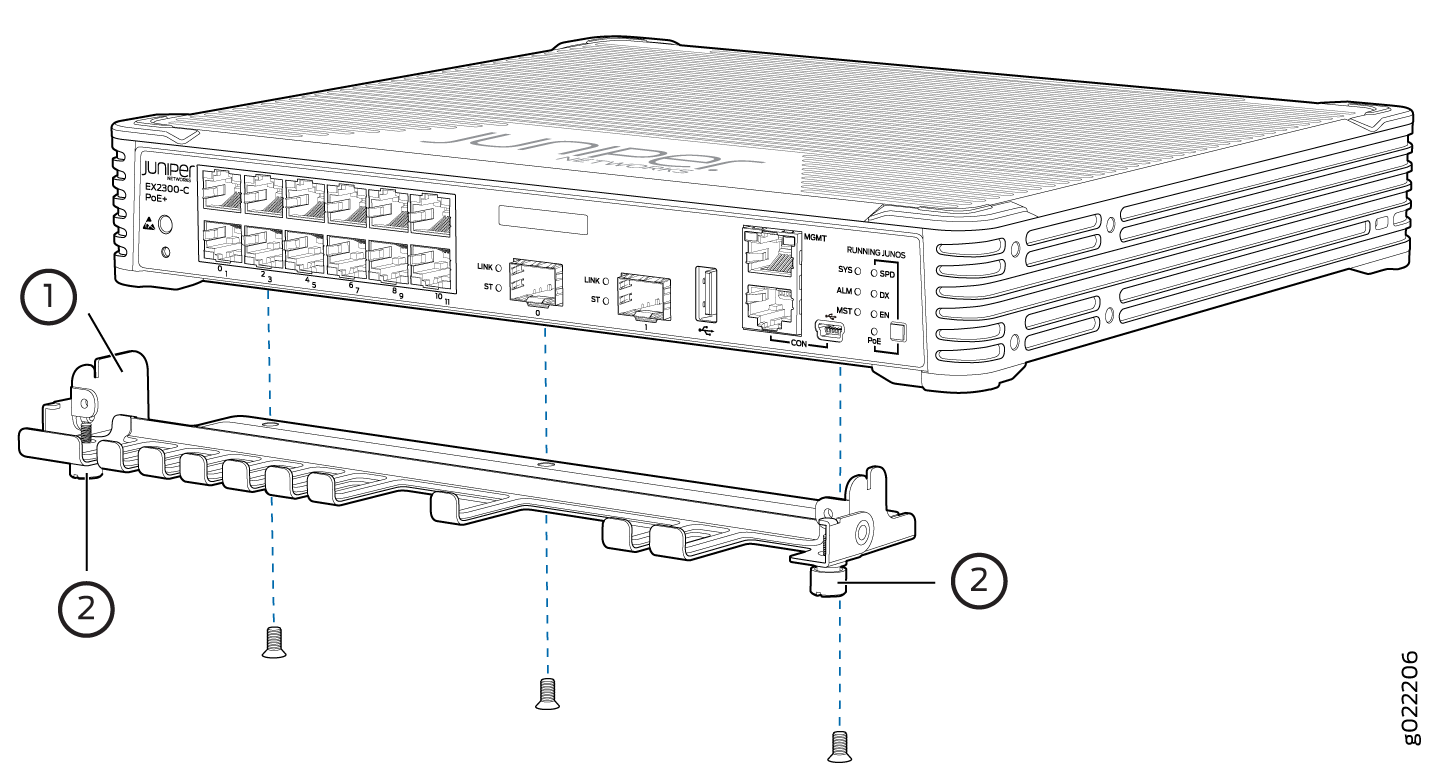 1—
1—Cable guard
2—Thumb screws
-
Use the thumbscrews to tighten or loosen the cable guard
so that you can insert cables. See Figure 1.
- Place the switch on the desk or the level surface.
- Ensure that the switch rests firmly on the desk or level surface.
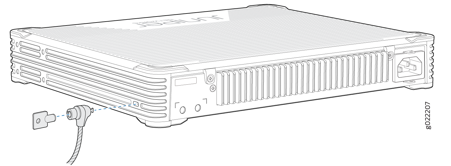
-
(Optional; applies only to EX2300-C switches) Attach the
standard cable lock to the security slot on the switch:
-
Insert the lock into the security slot on the switch and
set the lock to the locked position using the key. See Figure 2.
Figure 2: Securing the EX2300-C Switch by Using the Security Slot
-
Insert the lock into the security slot on the switch and
set the lock to the locked position using the key. See Figure 2.
Mounting an EX2300-C Switch Under a Desk or Other Level Surface by Using Screws
Before mounting the switch under a desk or other lever surface by using screws:
-
Verify that the site meets the requirements described in Site Preparation Checklist for EX2300 Switches.
-
Place the desk in its permanent location, allowing adequate clearance for airflow and maintenance, and secure it to the building structure.
-
Read General Safety Guidelines and Warnings, with particular attention to Chassis and Component Lifting Guidelines.
-
Remove the switch from the shipping carton (see Unpacking an EX2300 Switch).
Do not block the vents on the top of EX2300-C switches. Blocking the vents can lead to overheating of the switch chassis.
Ensure that you have the following parts and tools available:
-
3 desk-mounting screws (M4 x 30 mm or 8-32 x 1.25 in. Phillips pan-head machine screws—not provided)
-
Phillips (+) screwdriver, number 2
-
(Optional and separately orderable) 1 cable guard kit. The kit includes the cable guard and 3 number-8 Phillips truss-head screws to secure the cable guard to the switch.
-
(Optional and separately orderable) 1 standard cable lock kit to secure the switch from theft by connecting the cable to the security slot on the switch and a desk or a rack to fasten the cable lock. The kit includes the standard cable lock and its key.
You can mount an EX2300-C switch under a desk or other level surface by using the mounting slots on the bottom of the chassis and desk-mounting screws to secure the switch.
To mount the switch under a desk or other level surface by using screws:
-
(Optional) Attach the cable guard to protect cable connections:
-
Use the thumbscrews to fasten or loosen the cable guard
so that you can insert cables. See Figure 3.
Figure 3: Attaching a Cable Guard to an EX2300-C Switch
1—
Cable guard
2—Thumb screws
-
Use the thumbscrews to fasten or loosen the cable guard
so that you can insert cables. See Figure 3.
-
Install three mounting screws under the desk or the level
surface at the locations A, B, and C shown in Figure 4.
Note:
Figure 4 shows the bottom panel of an EX2300-C switch when the switch is viewed from the top. The internal components and top cover are not shown.
Figure 4: Measurements for Installing Mounting Screws for Mounting EX2300-C Switches Under a Desk or Other Level Surface by Using Screws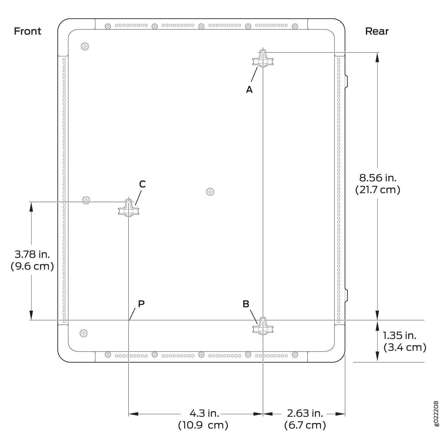 Note:
Note:Tighten the screws only part way in, leaving about 1/4 in. (6 mm) distance between the head of the screw and the desk or the level surface.
- Drill a hole A and install a mounting screw.
- Drill a hole B at a distance of 8.56 in. (21.7 cm) on a level line from hole A and install a mounting screw.
- Mark a point P at a distance of 4.3 in. (10.9 cm) on a level line to the right from hole B.
- Drill a hole C at a distance of 3.78 in. (9.6 cm) on a level line from point P and install a mounting screw.
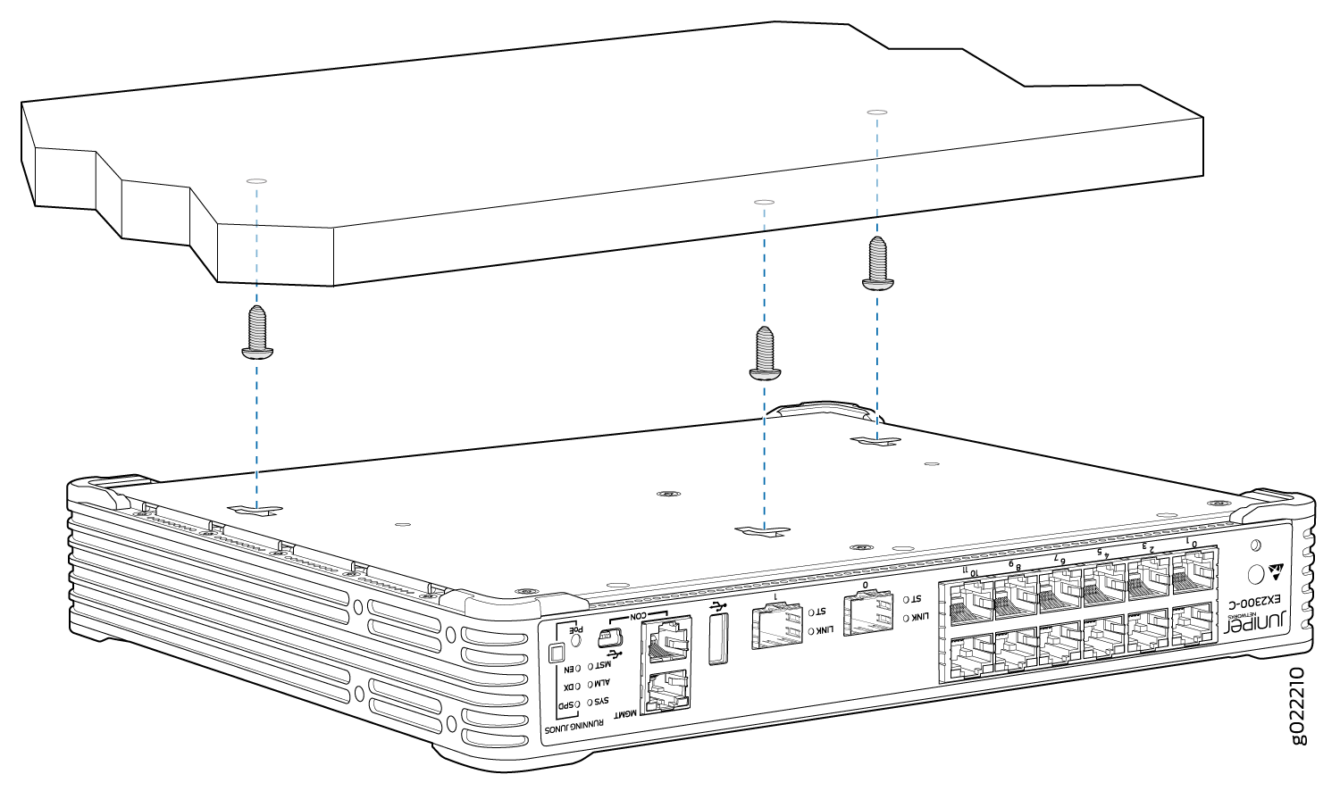
-
For mounting the switch under a desk or other level surface,
hold the switch such that the holes on the bottom panel of the switch
align with the screw heads, lift the switch, and then slide the switch
forward or backward until it locks in place. See Figure 5.
Figure 5: Mounting the EX2300-C Switch Under a Desk or Other Level Surface by Using Screws
-
(Optional) Attach the standard cable lock to the security
slot on the switch:
-
Insert the lock into the security slot on the switch and
set the lock to the locked position using the key. See Figure 6.
Figure 6: Securing the EX2300-C Switch by Using the Security Slot
-
Insert the lock into the security slot on the switch and
set the lock to the locked position using the key. See Figure 6.
Mounting an EX2300 Switch on Two Posts of a Rack or Cabinet
Before mounting the switch on two posts of a two-post or a four-post rack:
Verify that the site meets the requirements described in Site Preparation Checklist for EX2300 Switches.
Place the rack in its permanent location, allowing adequate clearance for airflow and maintenance, and secure it to the building structure.
Read General Safety Guidelines and Warnings, with particular attention to Chassis and Component Lifting Guidelines.
Ensure that you have the following parts and tools available:
Phillips (+) screwdriver, number 2
2 mounting brackets and 8 mounting screws (provided with EX2300 switches except the EX2300-C switch model and separately orderable for EX2300-C switches)
Screws to secure the chassis to the rack (not provided)
2-in.-recess front-mounting brackets from the separately orderable four-post rack-mount kit if you will mount the switch in a recessed position (not applicable for EX2300-C switches)
You can mount all EX2300 switches on two posts of a two-post or a four-post 19-in. rack or cabinet by using the mounting brackets and screws provided with EX2300 switches except the EX2300-C switch models. For EX2300-C switches, mounting brackets and screws are separately orderable. The remainder of this topic uses rack to mean rack or cabinet.
If you need to mount an EX2300 switch except the EX2300-C switch models in a recessed position on either a two-post rack or a four-post rack, you can use the 2-in.-recess front-mounting brackets provided in the separately orderable four-post rack-mount kit. EX2300-C cannot be mounted in a recessed position.
Do not block the vents on the top of EX2300-C switches. Blocking the vents can lead to overheating of the switch chassis.
One person must be available to lift the switch while another secures the switch to the rack.
If you are mounting multiple units on a rack, mount the heaviest unit at the bottom of the rack and mount the other units from the bottom of the rack to the top in decreasing order of the weight of the units.
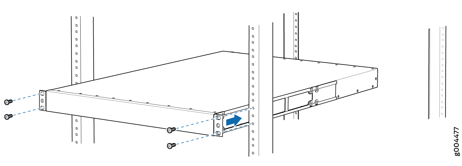
To mount the switch on two posts of a two-post or a four-post rack:
- Align the mounting brackets along the front or rear of
the side panels of the switch chassis depending on how you want to
mount the switch. For example, if you want to front-mount the switch,
align the brackets along the front of the chassis. Figure 7 shows how to attach
the mounting brackets along the front of the EX2300 switch.Figure 7: Attaching the Mounting Bracket Along the Front of the Switch
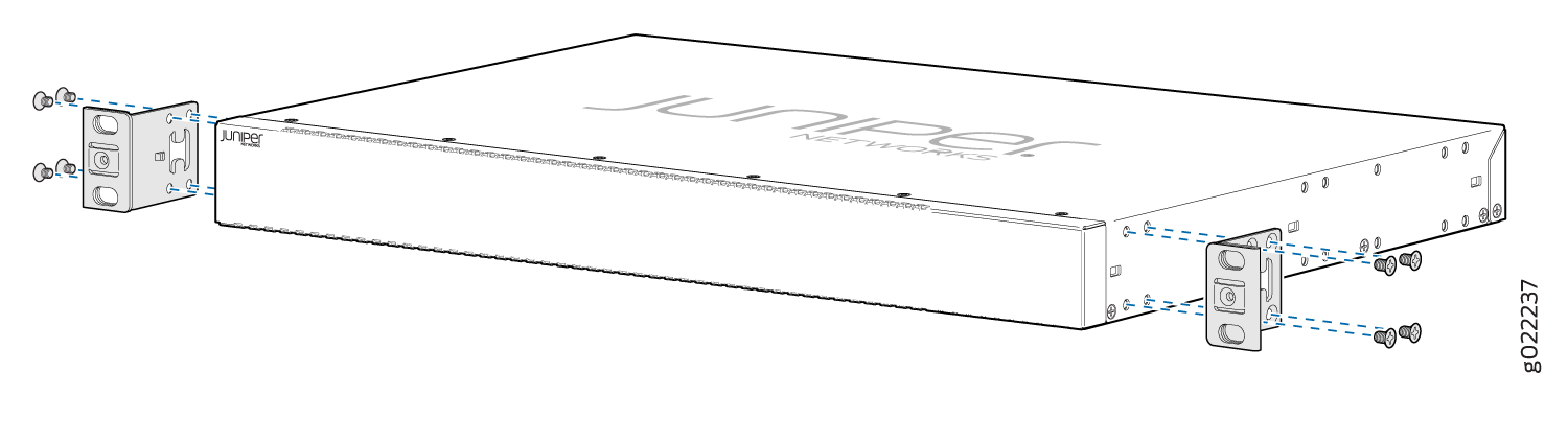 Note:
Note:The length of the mounting brackets depends on the switch model.
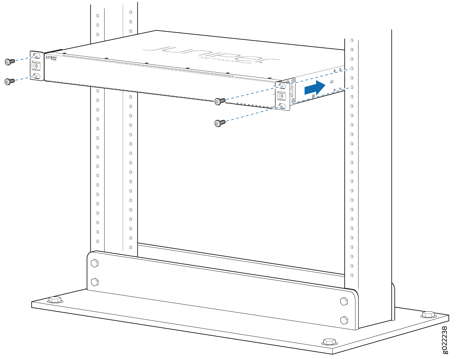
- Have one person grasp both sides of the switch, lift the
switch, and position it in the rack, aligning the mounting bracket
holes with the threaded holes in the rack rail. Align the bottom hole
in each mounting bracket with a hole in each rack rail, making sure
the chassis is level. See Figure 8.Figure 8: Mounting the Switch on Two Posts of a Rack
Mounting an EX2300 Switch on Four Posts of a Rack or Cabinet
Before mounting the switch on four posts of a rack:
-
Verify that the site meets the requirements described in Site Preparation Checklist for EX2300 Switches.
-
Place the rack in its permanent location, allowing adequate clearance for airflow and maintenance, and secure it to the building structure.
-
Read General Safety Guidelines and Warnings, with particular attention to Chassis and Component Lifting Guidelines.
Ensure that you have the following parts and tools available:
-
Phillips (+) screwdriver, number 2
-
6 Phillips 4-40 flat-head mounting screws (provided with the four-post rack-mount kit)
-
8 Phillips 4x6-mm flat-head mounting screws (provided with the four-post rack-mount kit)
-
One pair each of flush or 2-in.-recess front-mounting brackets
-
One pair of side mounting-rails
-
One pair of rear mounting-blades
-
Screws to secure the chassis and the rear mounting-blades to the rack (not provided)
You can mount an EX2300 switch except the EX2300-C switch model on four posts of a 19-in. rack or cabinet by using the separately orderable four-post rack-mount kit. The remainder of this topic uses rack to mean rack or cabinet.
EX2300-C switches cannot be mounted on all four posts of a rack.
If you need to mount an EX2300 switch except the EX2300-C switch model in a recessed position on either a two-post rack or a four-post rack, you can use the 2-in.-recess front-mounting brackets provided in the separately orderable four-post rack-mount kit. EX2300-C switches cannot be mounted in a recessed position.
One person must be available to lift the switch while another secures it to the rack.
If you are mounting multiple units on a rack, mount the heaviest unit at the bottom of the rack and mount the other units from the bottom of the rack to the top in decreasing order of the weight of the units.
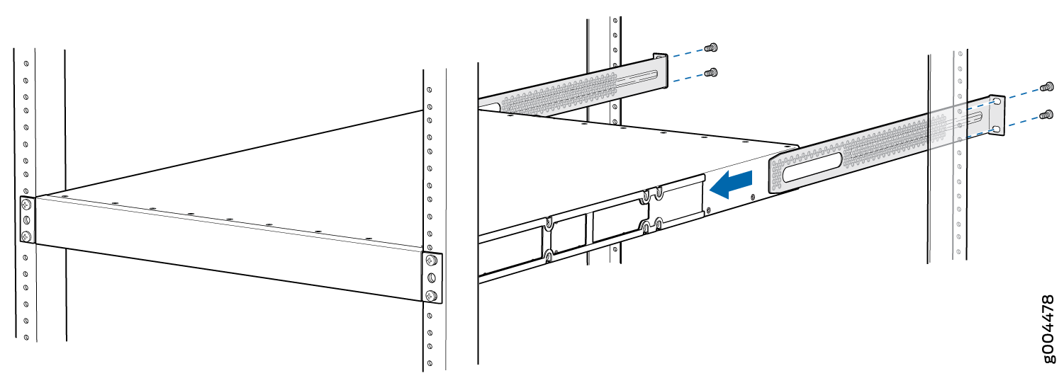
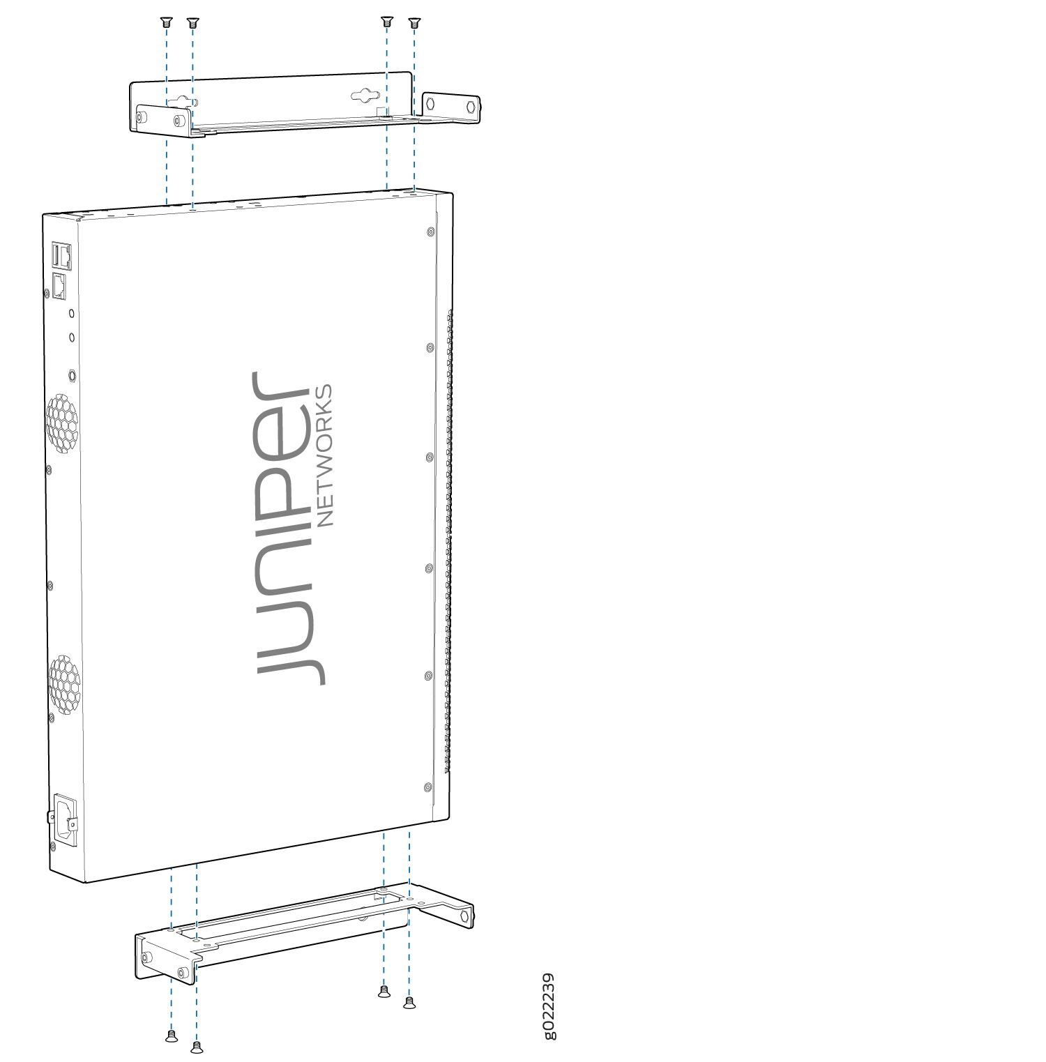
To mount the switch on four posts of a rack:
-
Attach the front-mounting brackets (either the flush or
the 2-in.-recess brackets) to the side mounting-rails by using 6 Phillips
4-40 flat-head mounting screws. See Figure 9.
Figure 9: Attaching the Front-Mounting Bracket to the Side Mounting-Rail
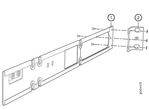 1—
1—Side mounting-rail
2—Front-mounting bracket
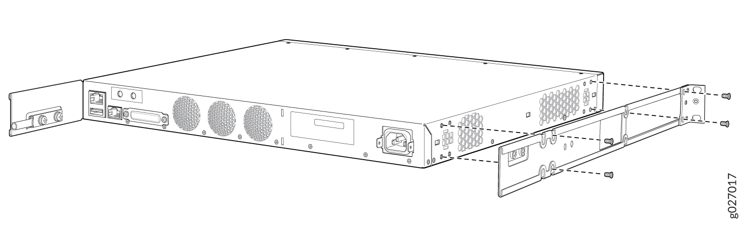
-
Insert the Phillips 4x6-mm flat-head mounting screws into
the two aligned holes and tighten the screws. Ensure that the two
holes in the rear of the side mounting-rails are aligned with the
remaining two holes in the side panel. See Figure 10.
Figure 10: Attaching the Side Mounting-Rail to the Switch Chassis
-
Have one person grasp both sides of the switch, lift the
switch, and position it in the rack, aligning the side mounting-rail
holes with the threaded holes in the front post of the rack. Align
the bottom hole in both the front-mounting brackets with a hole in
each rack rail, making sure that the chassis is level. See Figure 11.
Figure 11: Mounting the Switch to the Front Posts of a Rack
-
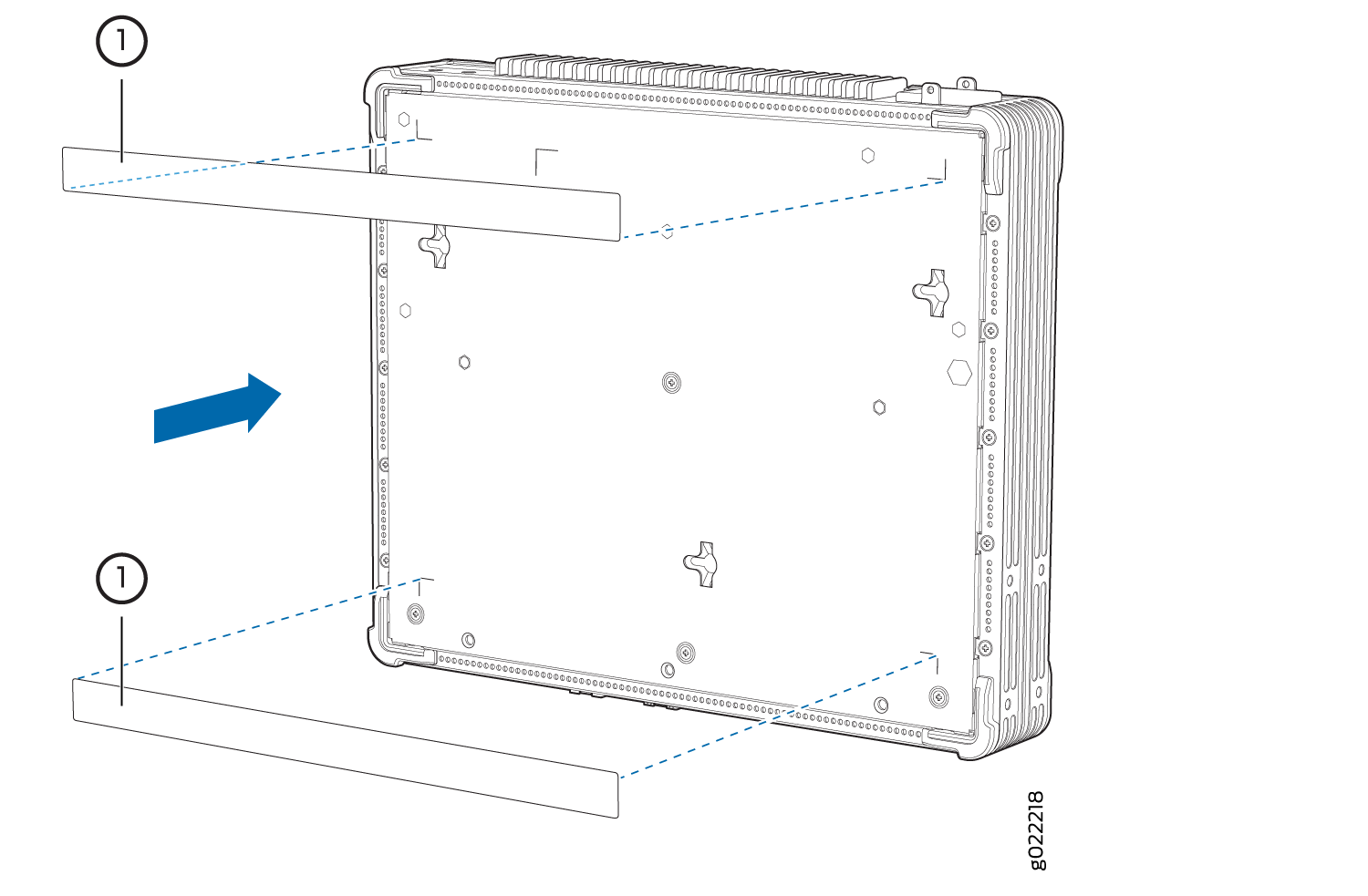
Slide the rear mounting-blades into the side mounting-rails.
See Figure 12.
Figure 12: Sliding the Rear Mounting-Blades into the Side Mounting-Rail
Mounting an EX2300 Switch on a Wall
This topic describes the process of mounting an EX2300 switch on a wall. You can mount EX2300 switches except the EX2300-24MP and EX2300-48MP models on a wall.
When mounting an EX2300 switch chassis on a wall, orient the front panel of the chassis to the right side.
- Mounting an EX2300-C Switch on a Wall
- Mounting an EX2300 Switch Except the EX2300-C Switch and the EX2300-24MP and EX2300-48MP Models on a Wall
Mounting an EX2300-C Switch on a Wall
Before mounting the switch on a wall:
-
Verify that the site meets the requirements described in Site Preparation Checklist for EX2300 Switches.
-
Read General Safety Guidelines and Warnings, with particular attention to Chassis and Component Lifting Guidelines.
Ensure that you have the following parts and tools available:
-
3 wall-mounting screws (M4 x 30 mm or 8-32 x 1.25 in. Phillips pan-head machine screws—not provided)
-
Phillips (+) screwdriver, number 2
-
Hollow wall anchors rated to support up to 75 lb (34 kg) if you are not inserting the mounting screws directly into wall studs.
-
(Optional and separately orderable) 1 cable guard kit. The kit includes the cable guard and 3 number-8 Phillips truss-head screws to secure the cable guard to the EX2300-C switch.
-
(Optional and separately orderable) 1 standard cable lock kit to secure the switch from theft by connecting the cable to the security slot on the switch and a desk or a rack to fasten the cable lock. The kit includes the standard cable lock and its key.
You can mount an EX2300-C switch—the compact, fanless model—on a wall by using the mounting slots on the bottom of the chassis and mounting screws to secure the switch.
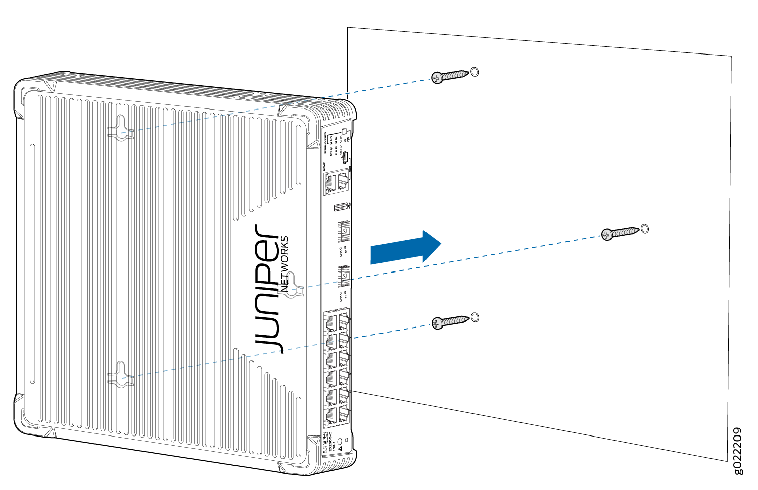
To mount the switch on a wall:
-
(Optional) Attach the optional cable guard to protect
cable connections:
-
Use the thumbscrews to fasten or loosen the cable guard
so that you can insert cables. See Figure 13.
Figure 13: Attaching a Cable Guard to an EX2300-C Switch
1—
Cable guard
2—Thumb screws
-
Use the thumbscrews to fasten or loosen the cable guard
so that you can insert cables. See Figure 13.
-
Install three mounting screws on the wall as shown in Figure 14.
Note:
Figure 14 shows the bottom panel of an EX2300-C switch when the switch is viewed from the top. The internal components and top cover are not shown.
Figure 14: Measurements for Installing Mounting Screws for Mounting an EX2300-C Switch on a Wall
Note:Tighten the screws only part way in, leaving about 1/4 in. (6 mm) distance between the head of the screw and the wall.
- Drill a hole A and install a mounting screw.
- Drill a hole B at a distance of 8.56 in. (21.7 cm) on a plumb line from hole A and install a mounting screw.
- Mark a point P at a distance of 4.3 in. (10.9 cm) on a level line to the right from hole B.
- Drill a hole C at a distance of 3.78 in. (9.6 cm) on a level line to the top from point P and install a mounting screw.
-
Slide the switch chassis to the left or right a bit so
that the mounting screws are pushed into the channels of the holes
on the bottom panel until the switch locks firmly in place as shown
in Figure 15.
Figure 15: Mounting an EX2300-C Switch on a Wall
-
(Optional) Attach the optional standard cable lock to
the security slot on the side of the switch:
-
Insert the lock into the security slot on your chassis
and set the lock to the locked position using the key. See Figure 16.
Figure 16: Securing the EX2300-C Switch by Using the Security Slot
-
Insert the lock into the security slot on your chassis
and set the lock to the locked position using the key. See Figure 16.
Mounting an EX2300 Switch Except the EX2300-C Switch and the EX2300-24MP and EX2300-48MP Models on a Wall
Before mounting the switch on a wall:
-
Verify that the site meets the requirements described in Site Preparation Checklist for EX2300 Switches.
-
Read General Safety Guidelines and Warnings, with particular attention to Chassis and Component Lifting Guidelines.
Ensure that you have the following parts and tools available:
-
2 wall-mounting brackets (provided in the wall-mount kit)
-
12 wall-mounting bracket screws (provided in the wall-mount kit)
-
6 mounting screws (8-32 x 1.25 in. or M4 x 30 mm) (not provided)
-
Hollow wall anchors rated to support up to 75 lb (34 kg) if you are not screwing the screws directly into wall studs (not provided)
-
Phillips (+) screwdriver, number 2
You can mount an EX2300 switch except the EX2300-C switch and the EX2300-24MP and EX2300-48MP models on a wall by using the separately orderable wall-mount kit.
To mount the switch on a wall:
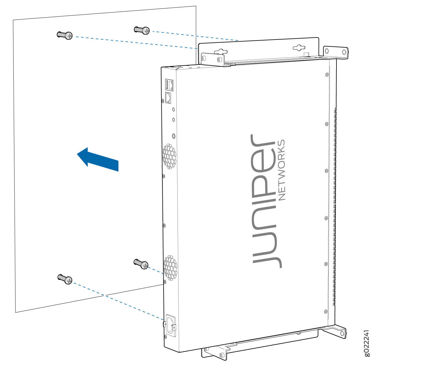
-
Attach the wall-mounting brackets to the sides of the
chassis by using four wall-mounting bracket screws, as shown in Figure 17.
Figure 17: Attaching Wall-Mount Brackets to an EX2300 Switch Except the EX2300-24MP and EX2300-48MP Models and the EX2300-C Switch
-
Install four mounting screws for the wall-mounting brackets
on the wall as shown in Figure 18.
Note:
Figure 18 shows an EX2300 switch with 24 ports with PoE capability when the switch is viewed from the top. The internal components and top cover are not shown. The procedure to mount the switch on a wall and the distance between mounting screws are the same for EX2300 switches with 24 ports with and without PoE capability though the depth of the chassis of the switches with and without PoE capability are different.
Note:Tighten the screws only part way in, leaving about 1/4 in. (6 mm) distance between the head of the screw and the wall.
-
Drill a hole D at a distance of 18.67 in. (47.43 cm)
on a plumb line down from screw B and install a mounting screw.
Figure 18: Measurements for Installing Mounting Screws to Mount an EX2300 Switch Except the EX2300-24MP and EX2300-48MP Models and the EX2300-C Switch on a Wall
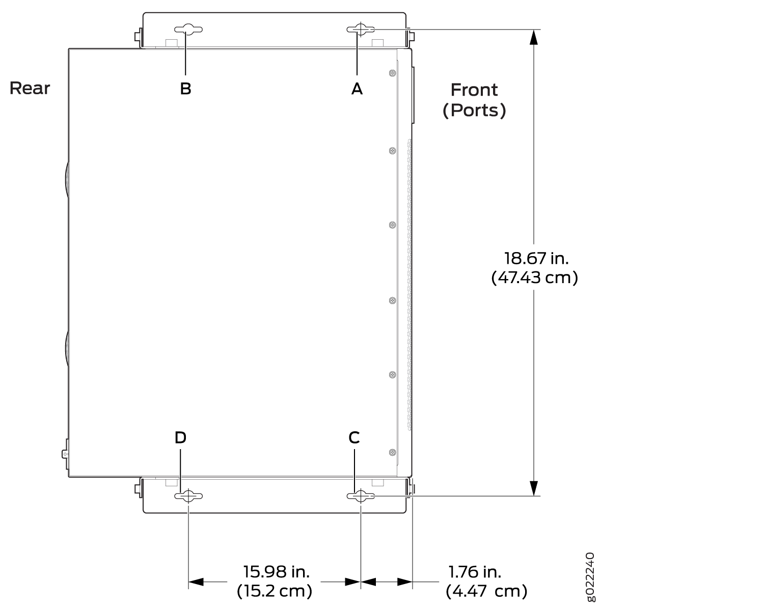
-
Drill a hole D at a distance of 18.67 in. (47.43 cm)
on a plumb line down from screw B and install a mounting screw.
Mounting an EX2300-C Switch on or Under a Surface Made of Ferrous Material
Before mounting the switch on or under a surface made of ferrous material:
-
Verify that the site meets the requirements described in Site Preparation Checklist for EX2300 Switches.
-
Place the surface made of ferrous material in its permanent location, allowing adequate clearance for airflow and maintenance.
-
Read General Safety Guidelines and Warnings, with particular attention to Chassis and Component Lifting Guidelines.
Ensure that you have the following parts and tools available:
-
Magnet-mount kit (separately orderable). The kit includes 2 self adhesive rubber pads and 1 magnet mount sheet.
-
At least 2-mm thick flat surface made of ferrous material (not provided)
-
(Optional and separately orderable) 1 cable guard kit. The kit includes the cable guard and 3 number-8 Phillips truss-head screws to secure the cable guard to the EX2300-C switch.
-
(Optional and separately orderable) 1 standard cable lock kit to secure the switch from theft by connecting the cable to the security slot on the switch and a desk or a rack to fasten the cable lock. The kit includes the standard cable lock and its key.
You can mount an EX2300-C switch on or under a surface made of ferrous material by using the separately orderable magnet-mount kit.
Do not mount EX2300-C switches on a ceiling by using the separately orderable magnet-mount kit.
Do not block the vents on the top of EX2300-C switches. Blocking the vents can lead to overheating of the switch chassis.
To mount the switch on or under a surface made of ferrous material:
-
(Optional) Attach the cable guard to protect cable connections:
-
Use the thumbscrews to tighten or loosen the cable guard
so that you can insert cables. See Figure 20.
Figure 20: Attaching a Cable Guard to an EX2300-C Switch
1—
Cable guard
2—Thumb screws
-
Use the thumbscrews to tighten or loosen the cable guard
so that you can insert cables. See Figure 20.
-
Attach the self adhesive rubber pads provided with the
magnet-mount kit to the bottom of the switch as shown in Figure 21.
Figure 21: Attaching Rubber Pads to an EX2300-C Switch
 1—
1—Self adhesive rubber pads
-
Attach the surface of the magnet mount sheet that has
the Running Junos logo to the rubber pads (see Figure 22).
Figure 22: Attaching the Magnet Mount Sheet to an EX2300-C Switch
 1—
1—Magnet mount sheet
-
Mount the switch along with the magnet mount sheet on
the ferrous surface on which you want to mount the switch (see Figure 23).
Figure 23: Mounting an EX2300-C Switch on or Under a Surface Made of Ferrous Material
 1—
1—Ferrous surface
-
(Optional) Attach the standard cable lock to the security
slot on the switch:
-
Insert the lock into the security slot on your chassis
and set the lock to the locked position using the key. See Figure 24.
Figure 24: Securing the EX2300-C Switch by Using the Security Slot
-
Insert the lock into the security slot on your chassis
and set the lock to the locked position using the key. See Figure 24.
Mounting an EX2300 Switch in a Recessed Position in a Rack or Cabinet
You can mount an EX2300 switch except the EX2300-C switch model on two posts or four posts of a rack or cabinet such that the switch is recessed inside the rack from the rack front by 2 inches. You can use the 2-in.-recess front-mounting brackets provided in the separately orderable four-post rack-mount kit to mount the switch in a recessed position.
Reasons that you might want to mount the switch in a recessed position include:
You are mounting the switch in a cabinet and the cabinet doors do not close completely unless the switch is recessed.
The switch you are mounting has transceivers installed in the uplink ports—the transceivers in the uplink ports protrude from the front of the switch.
To mount the switch in a recessed position on four posts, follow the instructions in Mounting an EX2300 Switch on Four Posts of a Rack or Cabinet. To mount the switch in a recessed position on two posts, follow the instructions in Mounting an EX2300 Switch on Two Posts of a Rack or Cabinet.