Maintaining an Uplink Module in an EX4300 Switch
Removing an Uplink Module from an EX4300 Switch
Before you begin removing an uplink module from the switch:
-
Ensure that you have taken the necessary precautions to prevent electrostatic discharge (ESD) damage (see Prevention of Electrostatic Discharge Damage).
-
If there are any transceivers installed in the uplink module, remove them before you remove the uplink module. For instructions on removing transceivers, see Remove a Transceiver.
Ensure that you have the following parts and tools available:
-
ESD grounding strap
-
Phillips (+) screwdriver, number 2
-
A replacement uplink module or cover panel
-
An antistatic bag or antistatic mat
The uplink module in EX4300 switches is hot-removable and hot-insertable field-replaceable unit (FRU): You can remove and replace it without powering off the switch or disrupting switch functions.
We recommend that you install either a replacement uplink module or a cover panel in the empty module slot to prevent chassis overheating and dust accumulation.
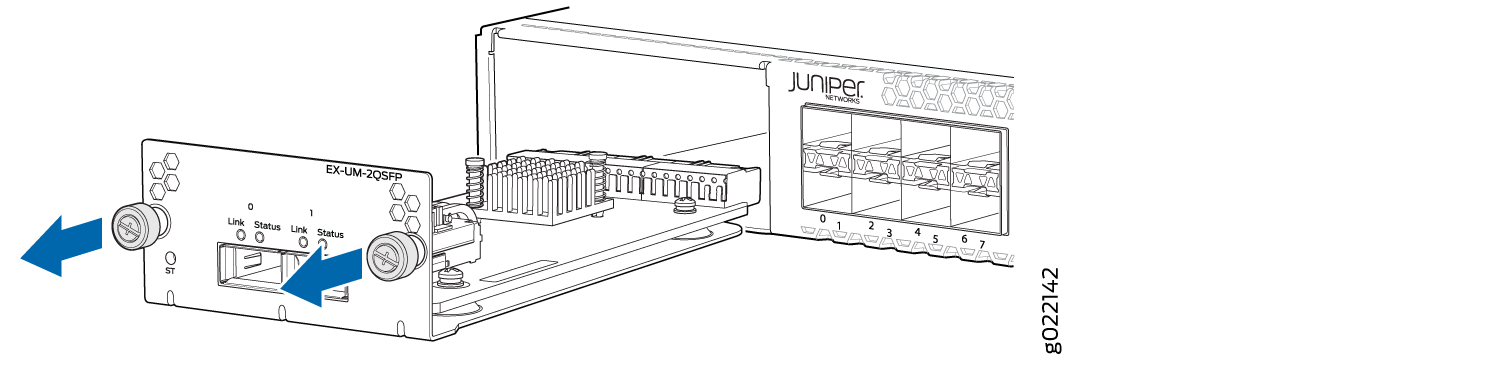
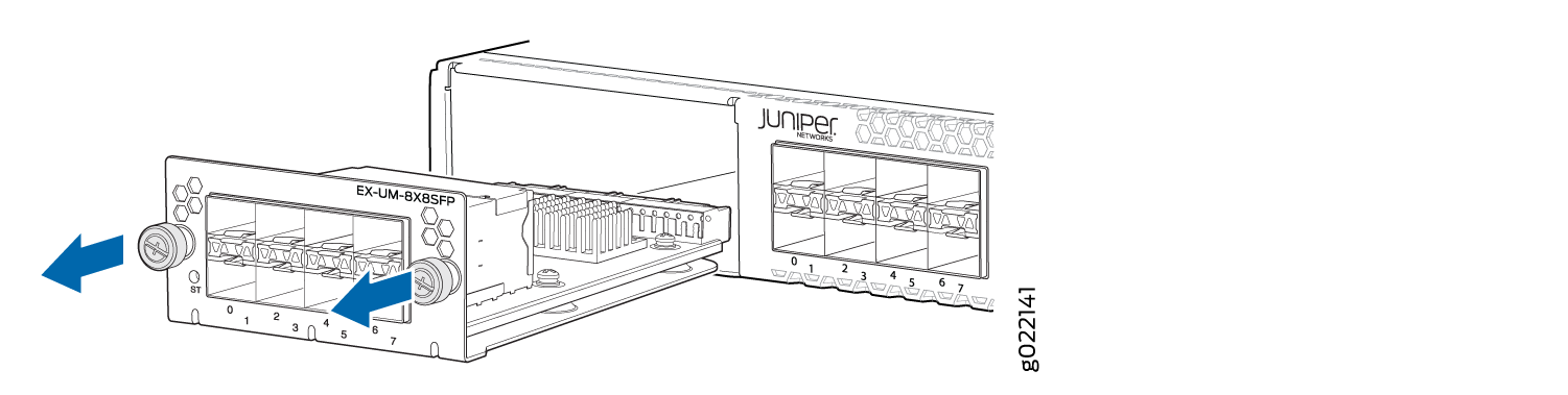
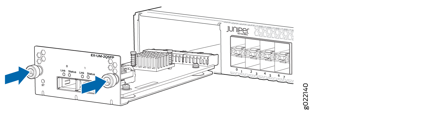
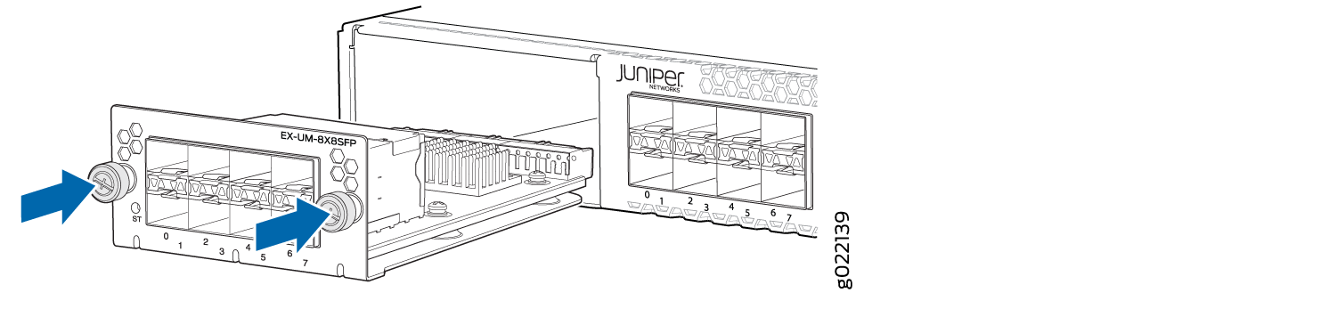
To remove an uplink module from the switch (see Figure 1, Figure 2, and Figure 3):
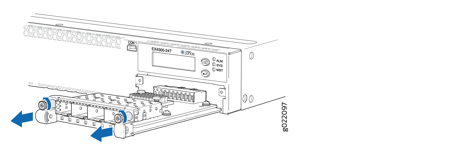
The procedure is the same for EX4300-48MP and EX4300-48MP-S switches.
Installing an Uplink Module in an EX4300 Switch
Before you begin installing an uplink module in the switch:
-
Ensure that you have taken the necessary precautions to prevent ESD damage (see Prevention of Electrostatic Discharge Damage).
Ensure that you have the following parts and tools available:
-
Electrostatic discharge (ESD) grounding strap (If a grounding strap is not available, follow the alternative grounding method described in Step 1 of the following procedure.)
-
Phillips (+) screwdriver, number 2
You can install an uplink module in the front panel of an EX4300 switch. The uplink module in EX4300 switches is a hot-removable and hot-insertable unit (FRU): You can remove and replace it without powering off the switch.
If you have set an uplink module port as a Virtual Chassis port (VCP), removing the uplink module breaks the setting. You must reset the port as a VCP after you replace the module. See Setting an Uplink Port on an EX Series or QFX Series Switch as a Virtual Chassis Port.
To install an uplink module in the switch (see Figure 4, Figure 5, and Figure 6):
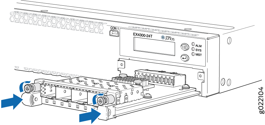
The procedure is the same for EX4300-48MP and EX4300-48MP-S switches.
If you have a Juniper J-Care service contract, register any addition, change, or upgrade of hardware components at https://www.juniper.net/customers/support/tools/updateinstallbase/ . Failure to do so can result in significant delays if you need replacement parts. This note does not apply if you replace existing components with the same type of component.