컬랩스드 스파인 패브릭 설계 및 구현
축소된 스파인 패브릭에서 코어 EVPN-VXLAN 오버레이 기능은 스파인 레이어로만 축소됩니다. 리프 레이어가 없습니다. 스파인 디바이스는 EVPN-VXLAN을 지원하지 않을 수 있는 액세스 레이어의 기존 ToR(Top-of-Rack) 스위치와 직접 인터페이스할 수 있습니다.
TOR 스위치는 액세스 레이어 복원을 위해 하나 이상의 스파인 디바이스 멀티호밍할 수 있으며, 스파인 디바이스는 다른 EVPN-VXLAN 참조 아키텍처에서 리프 디바이스와 동일한 방식으로 EVPN 멀티호밍(ESI-LAG이라고도 함)을 사용하여 관리할 수 있습니다. 자세한 내용은 이더넷 연결 엔드 시스템 설계 및 구현 멀티호밍 을 참조하십시오.)
또한 스파인 디바이스는 데이터센터 외부의 연결에 대해 경계 디바이스 역할을 맡습니다.
컬랩스드 스파인 아키텍처 사용 사례에서 일반적인 요소로는 다음이 포함됩니다.
스파인 디바이스가 백 투 백으로 연결된 컬랩스드 스파인 패브릭:
이 모델에서 스파인 디바이스는 포인트 투 포인트 링크로 연결됩니다. 스파인 디바이스는 루프백 주소를 사용하여 언더레이 및 오버레이에서 BGP 피어링을 설정합니다. 그림 1을 참조하십시오.
또는 축소된 스파인 코어 디바이스를 슈퍼 스파인 레이어의 경로 리플렉터 클러스터와 통합할 수 있습니다. 이는 나중에 설명됩니다(참조 아키텍처).
Data Center Interconnect(DCI)와 연결된 데이터센터 위치:
그림 1에서 볼 수 있듯이 스파인 디바이스는 경계 게이트웨이 기능을 수행하여 레이어 2 확장 및 레이어 3 연결을 포함한 데이터센터 간에 EVPN 피어링을 설정할 수 있습니다.
액세스 레이어의 독립 실행형 스위치 또는 Virtual Chassis:
ToR 레이어는 독립형 스위치 또는 컬랩스드 스파인 디바이스에 멀티호밍된 Virtual Chassis 포함할 수 있습니다. Virtual Chassis 통해 스파인 디바이스와 다양한 Virtual Chassis 멤버 스위치 간에 ESI-LAG에 중복 링크를 설정하여 복원력을 높일 수 있습니다. 그림 2를 참조하십시오.
그림 1 은 경계 연결이 있는 축소된 스파인 데이터센터, 데이터센터 간 DCI, 스파인 디바이스에 다중호밍된 ToR 레이어의 Virtual Chassis 대한 논리적 뷰를 보여줍니다.
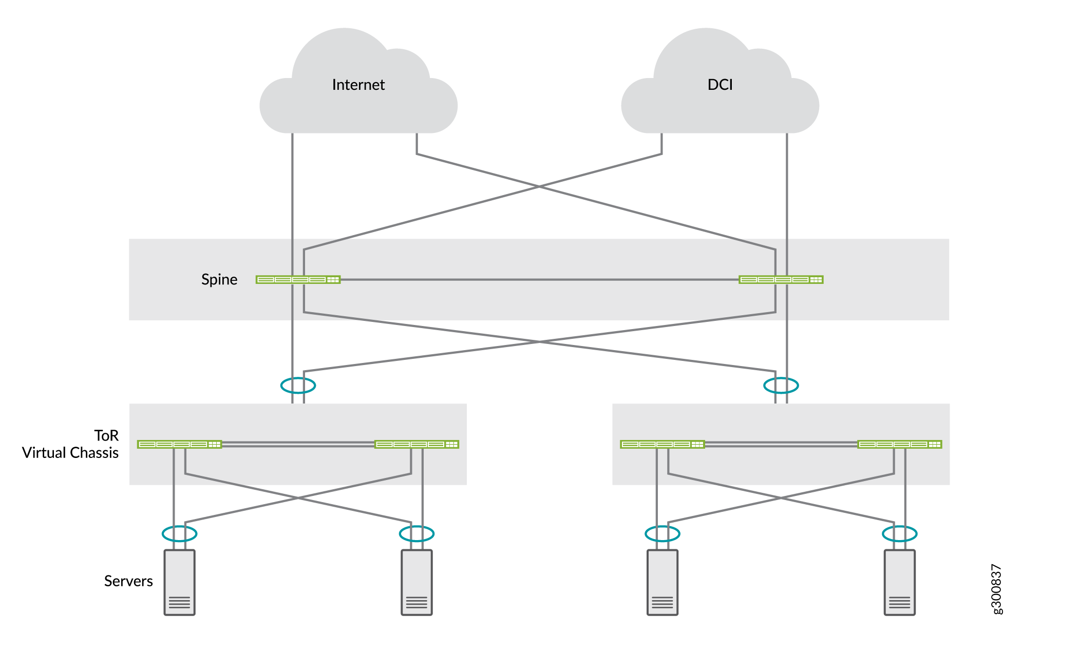 Data Center Interconnect 포함된 컬랩스드 스파인 데이터센터
그림 2 는 ESI-LAG 복원력을 개선하기 위해 스파인 디바이스가 다른 Virtual Chassis 멤버 스위치로 연결되는 백투백 축소 스파인 레이어에 다중 홉된 ToR 레이어의 Virtual Chassis 보여줍니다.
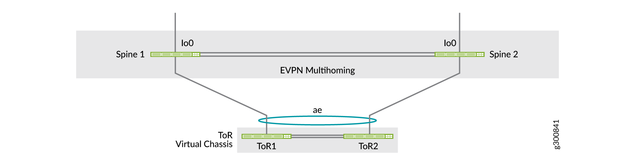 의 멀티호밍 Virtual Chassis 포함된 컬랩스드 스파인 설계
EVPN 멀티호밍(Multihoming)이 있는 축소 스파인을 참조하십시오. 이 예에서는 백 투 백 스파인 디바이스의 일반적인 축소 스파인 사용 사례를 설명합니다. 이 예에서 ToR 디바이스는 축소된 스파인 디바이스에 멀티호밍되는 Virtual Chassis. 이 예에는 SRX 섀시 클러스터를 사용하여 테넌트 간 트래픽을 보호하는 추가 보안 서비스를 구성하는 방법이 포함되며, 데이터센터 간 트래픽도 DCI 솔루션으로 SRX 클러스터를 통해 라우팅됩니다.
또 다른 축소된 스파인 패브릭 모델은 축소된 스파인 코어 언더레이 및 오버레이 네트워크와 통합되는 IP 전송 레이어 경로 리플렉터 클러스터를 통해 스파인 디바이스를 상호 연결합니다. 주니퍼의 참조 아키텍처는 이 모델을 사용하며 다음 섹션에서 설명합니다.
컬랩스드 스파인 참조 아키텍처 개요
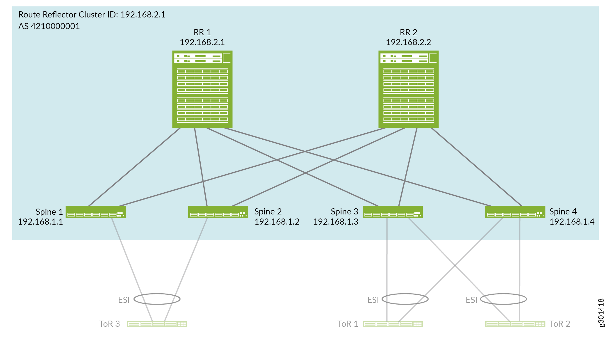
주니퍼의 참조 아키텍처는 2개의 POD(Inter-Point Delivery) 모듈로 구성된 컬랩스드 스파인 데이터센터 패브릭의 사용 사례를 제공합니다. POD의 POD 및 축소된 스파인 디바이스는 경로 리플렉터 클러스터로 구성된 슈퍼 스파인 IP 전송 레이어에 의해 상호 연결됩니다. 그림 3을 참조하십시오. 이 아키텍처는 5단계 IP 패브릭 설계( 5단계 IP 패브릭 설계 및 구현 참조)와 유사하지만 슈퍼 스파인, 스파인 및 액세스 레이어만을 사용합니다. 루트 리플렉터 클러스터 디바이스를 IP 패브릭 언더레이 및 EVPN 오버레이에 유사한 방식으로 통합하도록 축소 스파인 패브릭을 구성합니다.
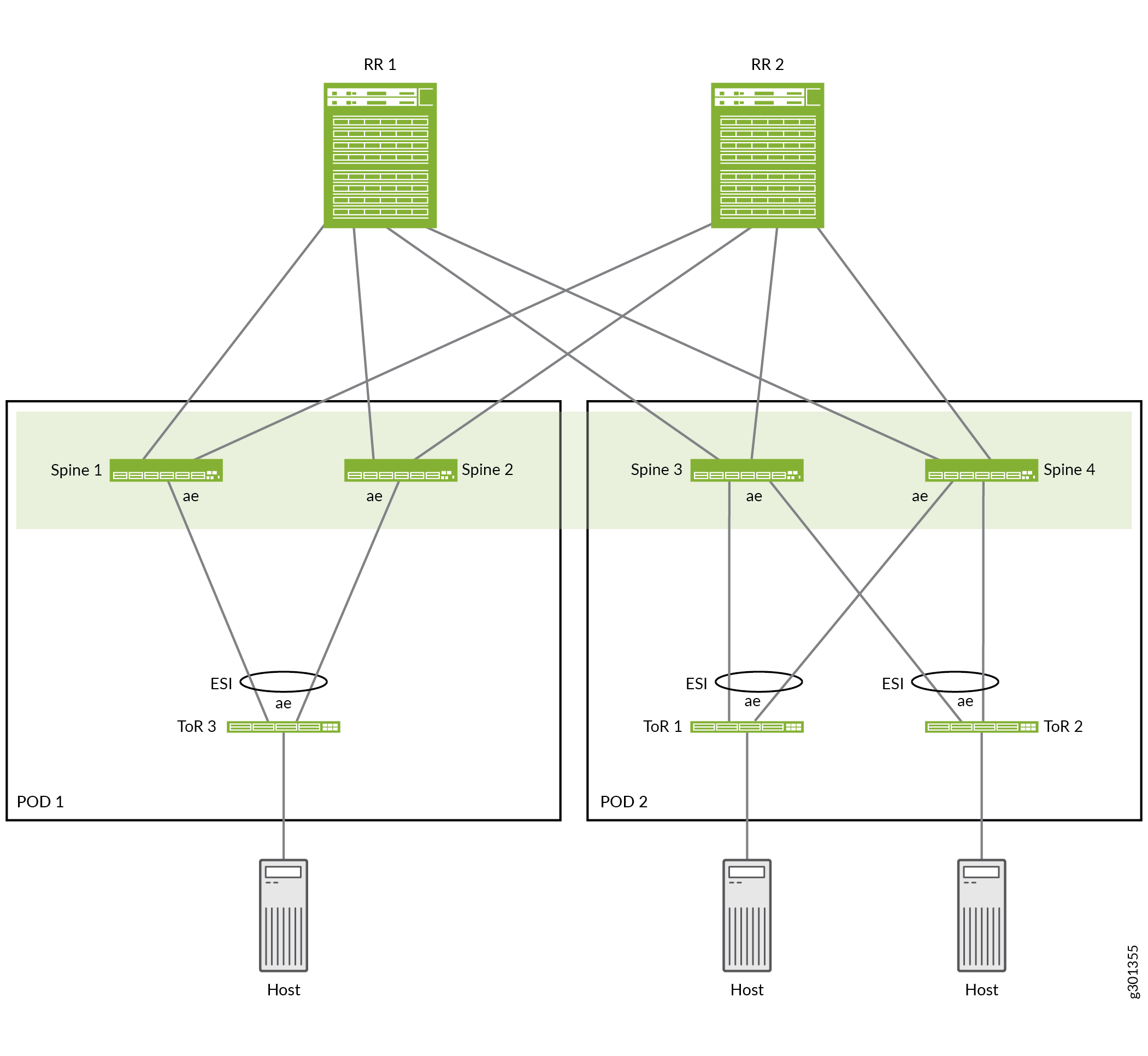
그림 3 은 컬랩스드 스파인 레퍼런스 설계의 예를 보여주며, 여기에는 다음 요소가 포함됩니다.
POD 1: ToR 3은 Spine 1 및 Spine 2에 멀티호밍됩니다.
POD 2: ToR 1 및 ToR 2는 Spine 3 및 Spine 4에 멀티호밍됨
경로 리플렉터 클러스터: RR 1 및 RR 2 상호 연결 스파인 디바이스 1~4
4개의 스파인 디바이스는 2개의 POD에서 스파인 디바이스 간에 레이어 2 확장 및 레이어 3 라우팅을 통해 축소된 스파인 EVPN 패브릭 코어를 구성합니다. 각 POD의 스파인 디바이스는 동일한 POD의 멀티호밍 ToR 스위치에 ESI-LAG를 사용합니다.
경로 리플렉터 레이어와 통합된 컬랩스드 스파인 IP 패브릭 언더레이 구성
이 섹션에서는 스파인 및 경로 리플렉터 디바이스에서 상호 연결된 링크와 IP 패브릭 언더레이를 구성하는 방법을 설명합니다.
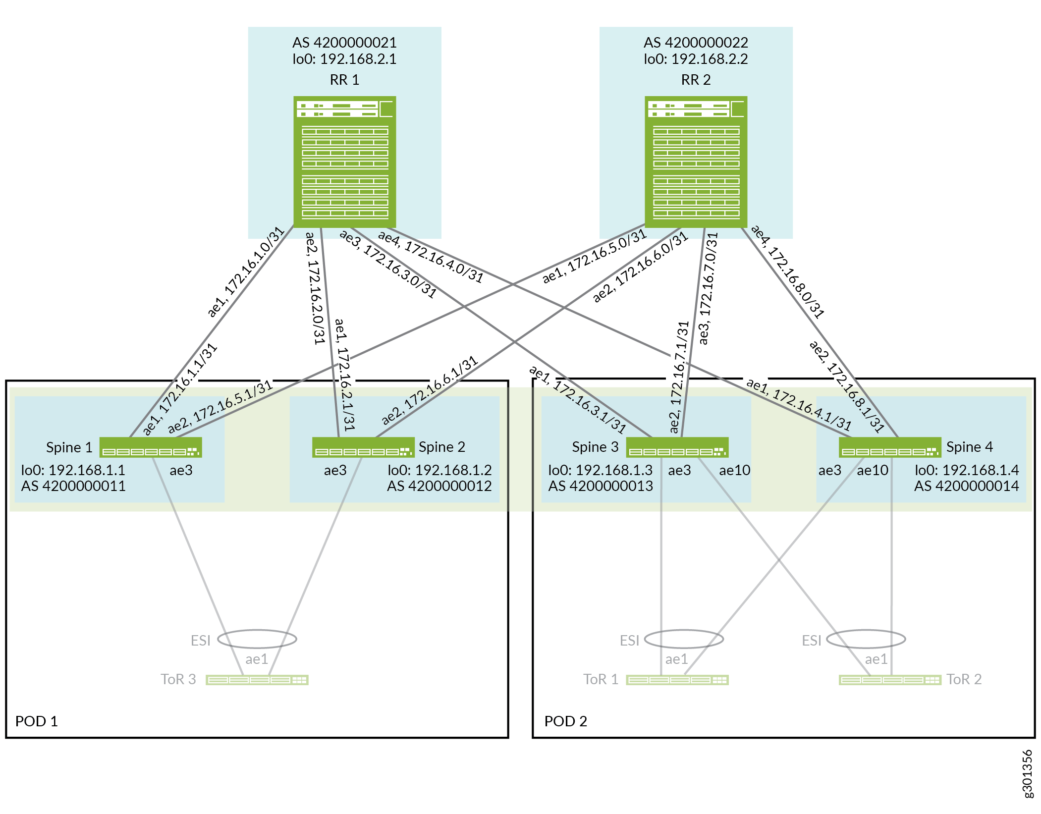
그림 4 는 어그리게이션 이더넷 인터페이스 링크로 연결된 축소된 스파인 및 경로 리플렉터 디바이스를 보여줍니다.
언더레이를 구성하려면 다음을 수행합니다.
- 패브릭에서 경로 리플렉터 및 스파인 디바이스를 연결하는 인터페이스를 구성하기 전에 각 디바이스에서 디바이스에 필요한 어그리게이션 이더넷 인터페이스 수를 설정해야 합니다. 디바이스는 구성한 각 어그리게이션 이더넷 인터페이스에 고유한 MAC 주소를 할당합니다.
RR 1, RR 2, Spine 1, Spine 2, Spine 3 및 Spine 4에서 어그리게이션 이더넷 인터페이스 수를 구성합니다.
set chassis aggregated-devices ethernet device-count 20
- 그림 4와 같이 축소된 스파인 패브릭을 형성하는 경로 리플렉터 및 스파인 디바이스에서 어그리게이션 이더넷 인터페이스를 구성합니다.
중복을 위해 이 레퍼런스 설계는 경로 리플렉터와 스파인 디바이스 사이의 각 어그리게이션 이더넷 링크에서 두 개의 물리적 인터페이스를 사용합니다. 경로 리플렉터 디바이스는 을(를) 통해
ae4어그리게이션 이더넷 인터페이스를 사용하여 4개의 스파인 디바이스에 연결됩니다ae1. 각 스파인 디바이스 어그리게이션 이더넷 인터페이스ae1(RR 1)와ae2(RR 2)를 사용합니다.또한 VXLAN 캡슐화를 고려하도록 물리적 인터페이스에서 더 높은 MTU(9192)를 구성합니다.
RR 1:
set interfaces et-0/0/46 ether-options 802.3ad ae1
set interfaces et-0/0/62 ether-options 802.3ad ae1

set interfaces et-0/0/9 ether-options 802.3ad ae2
set interfaces et-0/0/10 ether-options 802.3ad ae2

set interfaces et-0/0/49 ether-options 802.3ad ae3
set interfaces et-0/0/58 ether-options 802.3ad ae3

set interfaces xe-0/0/34:2 ether-options 802.3ad ae4
set interfaces xe-0/0/34:3 ether-options 802.3ad ae4

set interfaces ae1 mtu 9192
set interfaces ae1 aggregated-ether-options minimum-links 1
set interfaces ae1 aggregated-ether-options lacp active
set interfaces ae1 aggregated-ether-options lacp periodic fast
set interfaces ae1 unit 0 family inet address 172.16.1.0/31

set interfaces ae2 mtu 9192
set interfaces ae2 aggregated-ether-options minimum-links 1
set interfaces ae2 aggregated-ether-options lacp active
set interfaces ae2 aggregated-ether-options lacp periodic fast
set interfaces ae2 unit 0 family inet address 172.16.2.0/31

set interfaces ae3 mtu 9192
set interfaces ae3 aggregated-ether-options minimum-links 1
set interfaces ae3 aggregated-ether-options lacp active
set interfaces ae3 aggregated-ether-options lacp periodic fast
set interfaces ae3 unit 0 family inet address 172.16.3.0/31

set interfaces ae4 mtu 9192
set interfaces ae4 aggregated-ether-options minimum-links 1
set interfaces ae4 aggregated-ether-options lacp active
set interfaces ae4 aggregated-ether-options lacp periodic fast
set interfaces ae4 unit 0 family inet address 172.16.4.0/31
RR 2:
set interfaces et-0/0/18 ether-options 802.3ad ae1
set interfaces et-0/0/35 ether-options 802.3ad ae1

set interfaces et-0/0/13 ether-options 802.3ad ae2
set interfaces et-0/0/14 ether-options 802.3ad ae2

set interfaces et-0/0/22 ether-options 802.3ad ae3
set interfaces et-0/0/23 ether-options 802.3ad ae3

set interfaces et-0/0/19 ether-options 802.3ad ae4
set interfaces et-0/0/20 ether-options 802.3ad ae4

set interfaces ae1 mtu 9192
set interfaces ae1 aggregated-ether-options minimum-links 1
set interfaces ae1 aggregated-ether-options lacp active
set interfaces ae1 aggregated-ether-options lacp periodic fast
set interfaces ae1 unit 0 family inet address 172.16.5.0/31

set interfaces ae2 mtu 9192
set interfaces ae2 aggregated-ether-options minimum-links 1
set interfaces ae2 aggregated-ether-options lacp active
set interfaces ae2 aggregated-ether-options lacp periodic fast
set interfaces ae2 unit 0 family inet address 172.16.6.0/31

set interfaces ae3 mtu 9192
set interfaces ae3 aggregated-ether-options minimum-links 1
set interfaces ae3 aggregated-ether-options lacp active
set interfaces ae3 aggregated-ether-options lacp periodic fast
set interfaces ae3 unit 0 family inet address 172.16.7.0/31

set interfaces ae4 mtu 9192
set interfaces ae4 aggregated-ether-options minimum-links 1
set interfaces ae4 aggregated-ether-options lacp active
set interfaces ae4 aggregated-ether-options lacp periodic fast
set interfaces ae4 unit 0 family inet address 172.16.8.0/31
스파인 1:
set interfaces et-0/0/1 ether-options 802.3ad ae1
set interfaces et-0/0/2 ether-options 802.3ad ae1
set interfaces et-0/0/14 ether-options 802.3ad ae2
set interfaces et-0/0/27 ether-options 802.3ad ae2

set interfaces ae1 mtu 9192
set interfaces ae1 aggregated-ether-options minimum-links 1
set interfaces ae1 aggregated-ether-options lacp active
set interfaces ae1 aggregated-ether-options lacp periodic fast
set interfaces ae1 unit 0 family inet address 172.16.1.1/31

set interfaces ae2 mtu 9192
set interfaces ae2 aggregated-ether-options minimum-links 1
set interfaces ae2 aggregated-ether-options lacp active
set interfaces ae2 aggregated-ether-options lacp periodic fast
set interfaces ae2 unit 0 family inet address 172.16.5.1/31
스파인 2:
set interfaces et-0/0/1 ether-options 802.3ad ae1
set interfaces et-0/0/2 ether-options 802.3ad ae1

set interfaces et-0/0/14 ether-options 802.3ad ae2
set interfaces et-0/0/15 ether-options 802.3ad ae2

set interfaces ae1 mtu 9192
set interfaces ae1 aggregated-ether-options minimum-links 1
set interfaces ae1 aggregated-ether-options lacp active
set interfaces ae1 aggregated-ether-options lacp periodic fast
set interfaces ae1 unit 0 family inet address 172.16.2.1/31

set interfaces ae2 mtu 9192
set interfaces ae2 aggregated-ether-options minimum-links 1
set interfaces ae2 aggregated-ether-options lacp active
set interfaces ae2 aggregated-ether-options lacp periodic fast
set interfaces ae2 unit 0 family inet address 172.16.6.1/31
스파인 3:
set interfaces et-0/0/0 ether-options 802.3ad ae1
set interfaces et-0/0/1 ether-options 802.3ad ae1

set interfaces et-0/0/7 ether-options 802.3ad ae2
set interfaces et-0/0/8 ether-options 802.3ad ae2

set interfaces ae1 mtu 9192
set interfaces ae1 aggregated-ether-options minimum-links 1
set interfaces ae1 aggregated-ether-options lacp active
set interfaces ae1 aggregated-ether-options lacp periodic fast
set interfaces ae1 unit 0 family inet address 172.16.3.1/31

set interfaces ae2 mtu 9192
set interfaces ae2 aggregated-ether-options minimum-links 1
set interfaces ae2 aggregated-ether-options lacp active
set interfaces ae2 aggregated-ether-options lacp periodic fast
set interfaces ae2 unit 0 family inet address 172.16.7.1/31
스파인 4:
set interfaces xe-0/0/3:2 ether-options 802.3ad ae1
set interfaces xe-0/0/3:3 ether-options 802.3ad ae1

set interfaces et-0/0/19 ether-options 802.3ad ae2
set interfaces et-0/0/20 ether-options 802.3ad ae2

set interfaces ae1 mtu 9192
set interfaces ae1 aggregated-ether-options minimum-links 1
set interfaces ae1 aggregated-ether-options lacp active
set interfaces ae1 aggregated-ether-options lacp periodic fast
set interfaces ae1 unit 0 family inet address 172.16.4.1/31

set interfaces ae2 mtu 9192
set interfaces ae2 aggregated-ether-options minimum-links 1
set interfaces ae2 aggregated-ether-options lacp active
set interfaces ae2 aggregated-ether-options lacp periodic fast
set interfaces ae2 unit 0 family inet address 172.16.8.1/31
- 그림 4와 같이 루프백 인터페이스에 대한 IP 주소를 구성하고 각 경로 리플렉터 및 스파인 디바이스 대한 라우터 ID를 구성합니다.
set interfaces lo0 unit 0 family inet address addr/32
set routing-options router-id addr
- 경로 리플렉터 및 스파인 디바이스에서 EBGP IP 패브릭 언더레이를 구성합니다. 언더레이 구성은 IP 패브릭 언더레이 네트워크 설계 및 구현의 다른 스파인 및 리프 레퍼런스 아키텍처 설계와 유사합니다. 그러나 이 참조 설계의 언더레이에서 축소된 스파인 패브릭은 POD 내 및 전체 스파인 디바이스 간의 IP 전송 기능을 위한 경로 리플렉터 디바이스와 통합됩니다.
언더레이 구성에는 다음이 포함됩니다.
루프백 인터페이스의 IP 주소를 EBGP 피어링 디바이스에 보급하는 내보내기 라우팅 정책(
underlay-clos-export)를 정의합니다. 이 내보내기 라우팅 정책 IP 패브릭의 모든 디바이스(모든 경로 리플렉터 및 스파인 디바이스)가 연결할 수 있는 각 디바이스의 루프백 인터페이스의 IP 주소를 만드는 데 사용됩니다.각 디바이스에서 로컬 AS 번호를 정의합니다.
경로 리플렉터 디바이스에서: 어그리게이션 이더넷 링크 IP 주소 및 로컬 AS 번호에 의해 EBGP 이웃으로 네 개의 스파인 디바이스를 식별합니다.
스파인 디바이스에서: 어그리게이션 이더넷 링크 IP 주소와 로컬 AS 번호에 의해 EBGP 이웃으로 두 개의 경로 리플렉터 디바이스를 식별합니다.
BGP 피어 상태 전환 로깅을 켭니다.
RR 1:
set protocols bgp group underlay-bgp type external

set policy-options policy-statement underlay-clos-export term loopback from interface lo0.0
set policy-options policy-statement underlay-clos-export term loopback then accept
set protocols bgp group underlay-bgp export underlay-clos-export

set protocols bgp group underlay-bgp local-as 4200000021
set protocols bgp group underlay-bgp multipath multiple-as

set protocols bgp group underlay-bgp neighbor 172.16.1.1 peer-as 4200000011
set protocols bgp group underlay-bgp neighbor 172.16.2.1 peer-as 4200000012
set protocols bgp group underlay-bgp neighbor 172.16.3.1 peer-as 4200000013
set protocols bgp group underlay-bgp neighbor 172.16.4.1 peer-as 4200000014
set protocols bgp log-updown
RR 2:
set protocols bgp group underlay-bgp type external

set policy-options policy-statement underlay-clos-export term loopback from interface lo0.0
set policy-options policy-statement underlay-clos-export term loopback then accept
set protocols bgp group underlay-bgp export underlay-clos-export

set protocols bgp group underlay-bgp local-as 4200000022
set protocols bgp group underlay-bgp multipath multiple-as

set protocols bgp group underlay-bgp neighbor 172.16.5.1 peer-as 4200000011
set protocols bgp group underlay-bgp neighbor 172.16.6.1 peer-as 4200000012
set protocols bgp group underlay-bgp neighbor 172.16.7.1 peer-as 4200000013
set protocols bgp group underlay-bgp neighbor 172.16.8.1 peer-as 4200000014
set protocols bgp log-updown
스파인 1:
set protocols bgp group underlay-bgp type external

set policy-options policy-statement underlay-clos-export term loopback from interface lo0.0
set policy-options policy-statement underlay-clos-export term loopback then accept
set protocols bgp group underlay-bgp export underlay-clos-export

set protocols bgp group underlay-bgp local-as 4200000011
set protocols bgp group underlay-bgp multipath multiple-as

set protocols bgp group underlay-bgp neighbor 172.16.1.0 peer-as 4200000021
set protocols bgp group underlay-bgp neighbor 172.16.5.0 peer-as 4200000022

set protocols bgp log-updown
스파인 2:
set protocols bgp group underlay-bgp type external

set policy-options policy-statement underlay-clos-export term loopback from interface lo0.0
set policy-options policy-statement underlay-clos-export term loopback then accept
set protocols bgp group underlay-bgp export underlay-clos-export

set protocols bgp group underlay-bgp local-as 4200000012
set protocols bgp group underlay-bgp multipath multiple-as

set protocols bgp group underlay-bgp neighbor 172.16.2.0 peer-as 4200000021
set protocols bgp group underlay-bgp neighbor 172.16.6.0 peer-as 4200000022

set protocols bgp log-updown
스파인 3:
set protocols bgp group underlay-bgp type external

set policy-options policy-statement underlay-clos-export term loopback from interface lo0.0
set policy-options policy-statement underlay-clos-export term loopback then accept
set protocols bgp group underlay-bgp export underlay-clos-export

set protocols bgp group underlay-bgp local-as 4200000013
set protocols bgp group underlay-bgp multipath multiple-as

set protocols bgp group underlay-bgp neighbor 172.16.3.0 peer-as 4200000021
set protocols bgp group underlay-bgp neighbor 172.16.7.0 peer-as 4200000022

set protocols bgp log-updown
스파인 4:
set protocols bgp group underlay-bgp type external

set policy-options policy-statement underlay-clos-export term loopback from interface lo0.0
set policy-options policy-statement underlay-clos-export term loopback then accept
set protocols bgp group underlay-bgp export underlay-clos-export

set protocols bgp group underlay-bgp local-as 4200000014
set protocols bgp group underlay-bgp multipath multiple-as

set protocols bgp group underlay-bgp neighbor 172.16.4.0 peer-as 4200000021
set protocols bgp group underlay-bgp neighbor 172.16.8.0 peer-as 4200000022

set protocols bgp log-updown
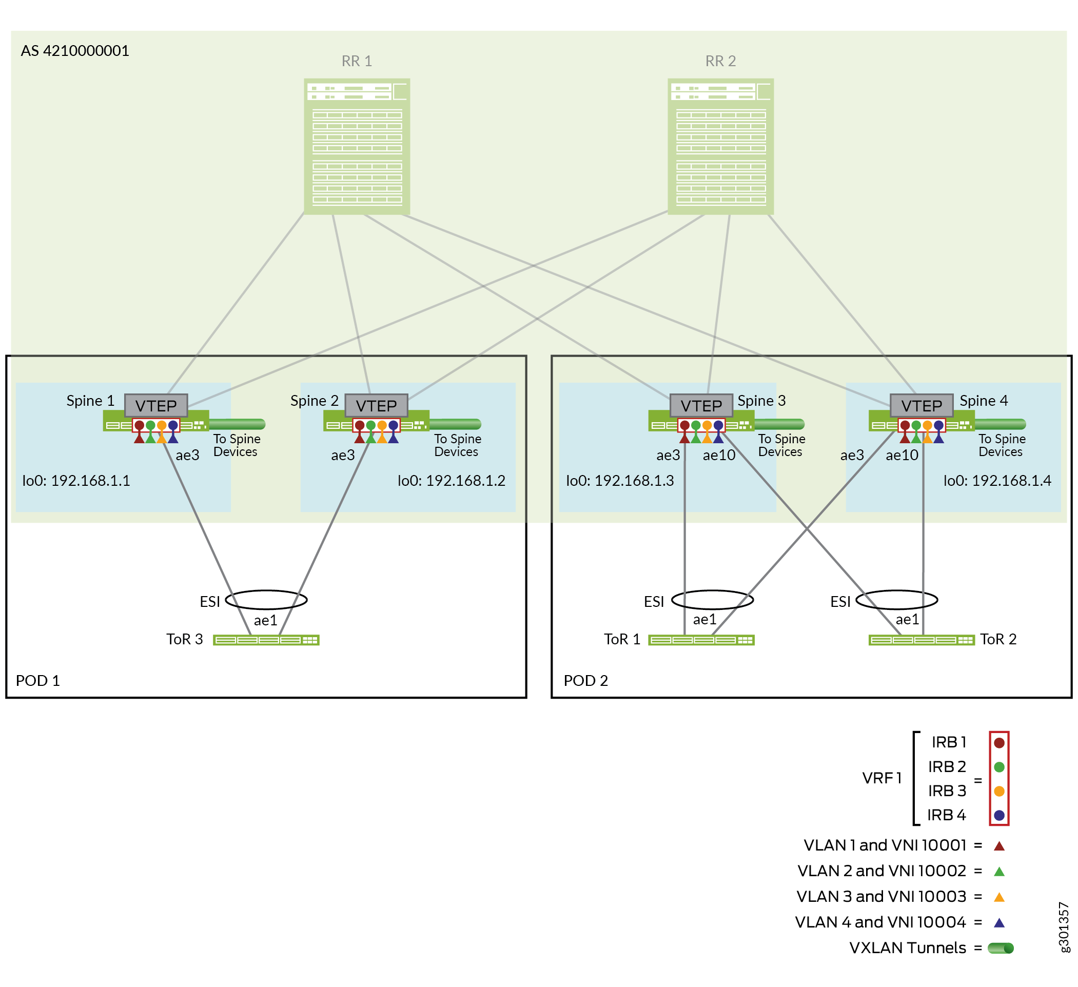
경로 리플렉터 레이어와 통합된 컬랩스드 스파인 EVPN-VXLAN 오버레이 구성
이러한 설계에서 오버레이는 다른 EVPN-VXLAN 데이터센터 스파인 및 리프 레퍼런스 아키텍처와 비슷하지만 리프 레이어는 포함하지 않습니다. 스파인 디바이스(경로 리플렉터 클러스터와 통합)만 패브릭에서 VLAN 내 및 VLAN 간 라우팅을 수행합니다. 스파인 디바이스에 단일 AS(Autonomous System) 번호가 있는 MP-IBGP(Multiprotocol BGP)를 사용하여 IBGP를 구성하여 다음과 같이 경로 리플렉터 클러스터 디바이스를 통해 그들 사이에 신호 경로를 설정합니다.
경로 리플렉터 클러스터 디바이스는 IP 전송을 위해 두 POD 모두에서 스파인 디바이스와 피어합니다.
스파인 디바이스는 경로 리플렉터 디바이스와 피어됩니다.
그림 5는 EVPN 오버레이 네트워크에서 구성하는 스파인 및 경로 리플렉터 클러스터 디바이스 및 BGP 인접 IP 주소를 보여줍니다.
오버레이 구성은 디바이스의 로컬 주소(루프백 주소)를 제외한 경로 리플렉터 디바이스 모두에서 동일합니다. 경로 리플렉터 디바이스는 모든 스파인 디바이스와 피어합니다.
오버레이 구성은 디바이스의 로컬 주소(루프백 주소)를 제외한 각 스파인 디바이스에서 동일합니다. 모든 스파인 디바이스는 경로 리플렉터 클러스터 디바이스와 피어됩니다.
주니퍼는 축소된 스파인 패브릭의 스파인 디바이스에서만 VXLAN 캡슐화 및 가상 터널 엔드포인트(VTEP) 인터페이스를 사용하여 EVPN을 구성합니다.
오버레이를 구성하려면 다음을 수행합니다.
- 모든 스파인 및 경로 리플렉터 디바이스에서 IBGP 오버레이에 대한 AS 번호를 구성합니다.
set routing-options autonomous-system 4210000001
- 그림 5와 같이 디바이스 루프백 주소에 의해 IBGP 이웃으로 식별되는 축소된 스파인 디바이스와 피어링하도록 경로 리플렉터 디바이스에 EVPN 시그널링으로 IBGP를 구성합니다.
이 단계에서는 다음을 수행합니다.
-
RR 1 및 RR 2를 경로 리플렉터 클러스터로 정의합니다(cluster ID 192.168.2.1).
-
경로 최대 전송 단위(MTU) 검색을 활성화하여 소스와 대상 간의 네트워크 경로에서 MTU 크기를 동적으로 결정하여 IP 단편화를 방지할 수 있습니다.
-
IBGP 인접 실패를 감지하기 위한 BFD(Bidirectional Forwarding Detection)를 설정합니다.
-
vpn-apply-export디바이스가 VPN 라우팅 테이블의 경로를 다른 경로 리플렉터 또는 스파인 디바이스에 보급하기 전에 BGP 구성의 VRF 및 BGP 그룹 또는 neighbor 내보내기 정책이 모두 적용되도록 하려면 옵션을 설정합니다. 자세한 내용은 VPN 경로 배포를 참조하십시오.)
RR 1:
set protocols bgp group overlay-with-rr type internal
set protocols bgp group overlay-with-rr local-address 192.168.2.1

set protocols bgp group overlay-with-rr family evpn signaling

set protocols bgp group overlay-with-rr cluster 192.168.2.1
set protocols bgp group overlay-with-rr multipath
set protocols bgp group overlay-with-rr mtu-discovery

set protocols bgp group overlay-with-rr neighbor 192.168.1.1
set protocols bgp group overlay-with-rr neighbor 192.168.1.2
set protocols bgp group overlay-with-rr neighbor 192.168.1.3
set protocols bgp group overlay-with-rr neighbor 192.168.1.4

set protocols bgp group overlay-with-rr bfd-liveness-detection minimum-interval 1000
set protocols bgp group overlay-with-rr bfd-liveness-detection multiplier 3
set protocols bgp group overlay-with-rr bfd-liveness-detection session-mode automatic

set protocols bgp group overlay-with-rr vpn-apply-export
RR 2:
set protocols bgp group overlay-with-rr type internal
set protocols bgp group overlay-with-rr local-address 192.168.2.2

set protocols bgp group overlay-with-rr family evpn signaling

set protocols bgp group overlay-with-rr cluster 192.168.2.1
set protocols bgp group overlay-with-rr multipath
set protocols bgp group overlay-with-rr mtu-discovery

set protocols bgp group overlay-with-rr neighbor 192.168.1.1
set protocols bgp group overlay-with-rr neighbor 192.168.1.2
set protocols bgp group overlay-with-rr neighbor 192.168.1.3
set protocols bgp group overlay-with-rr neighbor 192.168.1.4

set protocols bgp group overlay-with-rr bfd-liveness-detection minimum-interval 1000
set protocols bgp group overlay-with-rr bfd-liveness-detection multiplier 3
set protocols bgp group overlay-with-rr bfd-liveness-detection session-mode automatic

set protocols bgp group overlay-with-rr vpn-apply-export
-
- 그림 5에 표시된 디바이스 루프백 주소에 의해 IBGP 이웃으로 식별되는 경로 리플렉터 디바이스와 피어링하도록 축소된 스파인 디바이스에서 EVPN으로 IBGP를 구성합니다. 스파인 디바이스 루프백 IP 주소를 값으로 대체하는 것을 제외하고는 모든 스파인 디바이스에서 구성이
local-address device-loopback-addr동일합니다.이 단계에서는 다음을 수행합니다.
-
경로 최대 전송 단위(MTU) 검색을 활성화하여 소스와 대상 간의 네트워크 경로에서 MTU 크기를 동적으로 결정하여 IP 단편화를 방지할 수 있습니다.
-
IBGP 인접 실패를 감지하기 위한 BFD를 설정합니다.
-
vpn-apply-export디바이스가 VPN 라우팅 테이블의 경로를 다른 경로 리플렉터 또는 스파인 디바이스에 보급하기 전에 BGP 구성의 VRF 및 BGP 그룹 또는 neighbor 내보내기 정책이 모두 적용되도록 하려면 옵션을 설정합니다. 자세한 내용은 VPN 경로 배포를 참조하십시오.)
모든 스파인 디바이스:
set protocols bgp group overlay-with-rr type internal
set protocols bgp group overlay-with-rr local-address device-loopback-addr

set protocols bgp group overlay-with-rr family evpn signaling

set protocols bgp group overlay-with-rr multipath
set protocols bgp group overlay-with-rr mtu-discovery

set protocols bgp group overlay-with-rr neighbor 192.168.2.1
set protocols bgp group overlay-with-rr neighbor 192.168.2.2

set protocols bgp group overlay-with-rr bfd-liveness-detection minimum-interval 1000
set protocols bgp group overlay-with-rr bfd-liveness-detection multiplier 3
set protocols bgp group overlay-with-rr bfd-liveness-detection session-mode automatic

set protocols bgp group overlay-with-rr vpn-apply-export
-
- 경로 리플렉터 클러스터 및 스파인 디바이스의 관리 인터페이스(
em0)를 제외한 모든 인터페이스에서 LLDP가 활성화되었는지 확인합니다.모든 경로 리플렉터 및 스파인 디바이스:
set protocols lldp interface all
set protocols lldp interface em0 disable
- 스파인 디바이스의 오버레이에서 VXLAN 캡슐화로 EVPN을 구성합니다. 컬랩스드 스파인 패브릭의 모든 스파인 디바이스에서 구성이 동일합니다.
이 단계에서는 다음 단계를 수행합니다.
-
포워딩 테이블 ECMP에 대한 패킷당 로드 밸런싱을 위한 정책을 지정하고 적용합니다.
-
VXLAN 캡슐화 설정과 함께 [edit protocols evpn] 계층 수준에서 이러한 EVPN 옵션을 구성합니다.
-
default-gateway no-gateway-community: 이더넷 전용 에지 디바이스가 이러한 MAC 주소를 학습할 수 있도록 가상 게이트웨이 및 IRB MAC 주소를 EVPN 피어 디바이스에 보급합니다. 스파인에서 다음을 사용하는 경우 축소된 스파인 패브릭에서 을(를) 구성no-gateway-community합니다.-
애니캐스트 IP를 공통 애니캐스트 MAC 주소 게이트웨이 또는
-
VRRP 기반 MAC 주소 가상 게이트웨이 주소(00:00:5e:00:01:XX) (ToR 스위치용 스파인 디바이스의 EVPN 멀티호밍 구성의 5단계 참조)
-
-
extended-vni-list all옵션: 구성된 모든 VXLAN 네트워크 식별자(VPI)가 이 EVPN-VXLAN BGP 도메인의 일부가 되도록 허용합니다. 이후 섹션에서 VLAN과 VNI 매핑에 대한 VLAN과 VLAN을 구성합니다. -
remote-ip-host-routes: 가상 머신 트래픽 최적화(VMTO)를 활성화합니다. (자세한 내용은 EVPN의 수신 가상 머신 트래픽 최적화 를 참조하십시오.)
-
모든 스파인 디바이스:
set policy-options policy-statement per-packet-load-balance term 1 then load-balance per-packet
set routing-options forwarding-table export per-packet-load-balance

set protocols evpn encapsulation vxlan
set protocols evpn default-gateway no-gateway-community
set protocols evpn extended-vni-list all
set protocols evpn remote-ip-host-routes
-
- 스파인 디바이스에서 VTEP, 경로 대상 및 가상 라우팅 및 포워딩(VRF) 스위치 옵션을 구성합니다.
구성은 디바이스의 루프백 IP 주소를
route-distinguisher값으로 대체하는 각 디바이스를 제외한 모든 스파인 디바이스에서 동일합니다. 이 값은 각 디바이스에서 생성된 경로에 대해 고유한 경로 식별자를 정의합니다.EVPN 인스턴스의 VTEP 소스 인터페이스도 IBGP 로컬 피어 주소와 일치해야 합니다. 이는 마찬가지로 디바이스 루프백 IP 주소입니다.
스파인 1:
set switch-options vtep-source-interface lo0.0
set switch-options route-distinguisher 192.168.1.1:3333
set switch-options vrf-target target:10458:0
set switch-options vrf-target auto
스파인 2:
set switch-options vtep-source-interface lo0.0
set switch-options route-distinguisher 192.168.1.2:3333
set switch-options vrf-target target:10458:0
set switch-options vrf-target auto
스파인 3:
set switch-options vtep-source-interface lo0.0
set switch-options route-distinguisher 192.168.1.3:3333
set switch-options vrf-target target:10458:0
set switch-options vrf-target auto
스파인 4:
set switch-options vtep-source-interface lo0.0
set switch-options route-distinguisher 192.168.1.4:3333
set switch-options vrf-target target:10458:0
set switch-options vrf-target auto
- (PTX10000 시리즈 라우터에서만 필요) 디바이스에서 전역적으로 터널 종료(즉, 모든 인터페이스)를 활성화합니다.
set forwarding-options tunnel-termination
ToR 스위치용 스파인 디바이스에서 EVPN 멀티호밍 및 가상 네트워크 구성
이 축소된 스파인 레퍼런스 설계는 이 더넷 연결 엔드 시스템 설계 및 구현 멀티호밍에 설명된 대로 EVPN 멀티호밍을 구현합니다. 리프 레이어 기능이 스파인 레이어로 축소되므로 스파인 디바이스에서 ESI-LAG를 구성합니다. 또한 ERB(에지 라우팅 브리징) 오버레이 설계의 리프 디바이스와 마찬가지로 스파인 디바이스에서 VLAN 및 레이어 2 및 레이어 3 라우팅 기능을 유사한 방식으로 구성합니다. 코어 축소 스파인 구성은 두 POD의 모든 스파인 디바이스에서 동일한 VLAN(및 VLAN-VNI 매핑)을 설정하여 레이어 2 확장 기능을 구현합니다. EVPN Type 2 경로는 POD 내 및 전체 엔드포인트 간 통신을 지원합니다.
그림 6 은 어그리게이션 이더넷 인터페이스 링크와 연결된 각 POD의 축소된 스파인 디바이스를 POD의 멀티홈 ToR 스위치에 보여줍니다.
 드 스파인 패브릭
간결성을 위해 이 섹션은 각 스파인과 각 ToR 디바이스 사이에 하나의 어그리게이션 이더넷 링크를 보여주며, 스파인 디바이스에서 POD의 ToR 디바이스까지 각 어그리게이션 이더넷 링크에 하나의 인터페이스가 구성됩니다.
이 섹션에서는 POD 2의 스파인 및 ToR 디바이스에 대한 구성 세부 정보만 다룹니다. POD 1의 스파인 및 ToR 디바이스에 해당하는 디바이스 매개 변수 및 인터페이스와 유사한 구성을 적용할 수 있습니다.
ToR 디바이스는 어그리게이션 이더넷 링크에 두 개의 인터페이스를 포함하며, 이는 멀티호밍을 위한 ESI-LAG를 형성하는 POD의 각 스파인 디바이스 하나씩 포함합니다.
구성에는 다음 단계가 포함됩니다.
인터페이스를 구성합니다.
EVPN 멀티호밍을 위한 ESI-LAG를 설정합니다.
VLAN 정의, VLAN 간 라우팅을 위한 관련 IRB 인터페이스, 해당 VLAN-VNI 매핑을 포함한 레이어 2 및 레이어 3 게이트웨이 기능을 구성합니다.
- POD 2에서 멀티홈 ToR 스위치(ToR 1 및 ToR 2)로 스파인(Spine 3 및 Spine 4)의 인터페이스 및 어그리게이션 이더넷 링크를 구성합니다.
스파인 3:
set interfaces xe-0/0/22:0 hold-time up 450000
set interfaces xe-0/0/22:0 hold-time down 450000
set interfaces xe-0/0/22:0 ether-options 802.3ad ae3

set interfaces xe-0/0/23:0 hold-time up 450000
set interfaces xe-0/0/23:0 hold-time down 450000
set interfaces xe-0/0/23:0 ether-options 802.3ad ae10
스파인 4:
set interfaces xe-0/0/4:2 hold-time up 450000
set interfaces xe-0/0/4:2 hold-time down 450000
set interfaces xe-0/0/4:2 ether-options 802.3ad ae3

set interfaces xe-0/0/6:1 hold-time up 450000
set interfaces xe-0/0/6:1 hold-time down 450000
set interfaces xe-0/0/6:1 ether-options 802.3ad ae10
- POD 2에서 멀티호밍 ToR 스위치의 스파인 디바이스에서 EVPN 멀티호밍을 위한 ESI-LAG를 구성합니다. 이 설계는 스파인 디바이스에서 동일한 어그리게이션 이더넷 인터페이스를 ToR 스위치에 사용하므로 두 디바이스에서 동일한 구성을 사용합니다.
이 레퍼런스 설계
ae3에서는 ToR 1에 연결하고ae10ToR 2에 연결합니다.스파인 3 및 스파인 4:
set interfaces ae3 esi 00:00:00:ff:00:02:00:01:00:03
set interfaces ae3 esi all-active
set interfaces ae3 aggregated-ether-options lacp active
set interfaces ae3 aggregated-ether-options lacp periodic fast
set interfaces ae3 aggregated-ether-options lacp system-id 00:00:00:99:99:01
set interfaces ae3 aggregated-ether-options lacp hold-time up 300

set interfaces ae10 esi 00:00:00:ff:00:01:00:01:00:0a
set interfaces ae10 esi all-active
set interfaces ae10 aggregated-ether-options lacp active
set interfaces ae10 aggregated-ether-options lacp periodic fast
set interfaces ae10 aggregated-ether-options lacp system-id 00:00:00:99:99:01
set interfaces ae10 aggregated-ether-options lacp hold-time up 300
- POD 2
ae3에서 스파인 디바이스에 VLAN을 구성하고ae10VLAN 멤버로 구성합니다.스파인 3 및 스파인 4:
set interfaces ae3 native-vlan-id 4094
set interfaces ae3 unit 0 family ethernet-switching interface-mode trunk
set interfaces ae3 unit 0 family ethernet-switching vlan members VLAN-1
set interfaces ae3 unit 0 family ethernet-switching vlan members VLAN-2
set interfaces ae3 unit 0 family ethernet-switching vlan members VLAN-3
set interfaces ae3 unit 0 family ethernet-switching vlan members VLAN-4

set interfaces ae10 native-vlan-id 4094
set interfaces ae10 unit 0 family ethernet-switching interface-mode trunk
set interfaces ae10 unit 0 family ethernet-switching vlan members VLAN-1
set interfaces ae10 unit 0 family ethernet-switching vlan members VLAN-2
set interfaces ae10 unit 0 family ethernet-switching vlan members VLAN-3
set interfaces ae10 unit 0 family ethernet-switching vlan members VLAN-4
- VXLAN 터널을 위해 VLAN을 VPI에 매핑하고 IRB 인터페이스를 각 터널과 연결합니다.
스파인 3 및 스파인 4:
set vlans VLAN-1 vlan-id 1
set vlans VLAN-1 l3-interface irb.1
set vlans VLAN-1 vxlan vni 100001
set vlans VLAN-2 vlan-id 2
set vlans VLAN-2 l3-interface irb.2
set vlans VLAN-2 vxlan vni 100002
set vlans VLAN-3 vlan-id 3
set vlans VLAN-3 l3-interface irb.3
set vlans VLAN-3 vxlan vni 100003
set vlans VLAN-4 vlan-id 4
set vlans VLAN-4 l3-interface irb.4
set vlans VLAN-4 vxlan vni 100004
- IRB IP 주소 및 가상 게이트웨이 IP 주소 모두에 대한 IPv4 및 IPv6 이중 스택 주소를 사용하여 POD 2의 스파인 디바이스에서 VLAN(VPI)에 대한 IRB 인터페이스를 구성합니다.
스파인 3:
set interfaces irb unit 1 virtual-gateway-accept-data
set interfaces irb unit 1 family inet address 10.0.1.243/24 preferred
set interfaces irb unit 1 family inet address 10.0.1.243/24 virtual-gateway-address 10.0.1.254
set interfaces irb unit 1 family inet6 nd6-stale-time 3600
set interfaces irb unit 1 family inet6 address 2001:db8::10:0:1:243/112 preferred
set interfaces irb unit 1 family inet6 address 2001:db8::10:0:1:243/112 virtual-gateway-address 2001:db8::10:0:1:254
set interfaces irb unit 1 virtual-gateway-v4-mac 00:00:5e:00:00:04
set interfaces irb unit 1 virtual-gateway-v6-mac 00:00:5e:00:00:04

set interfaces irb unit 2 virtual-gateway-accept-data
set interfaces irb unit 2 family inet address 10.0.2.243/24 preferred
set interfaces irb unit 2 family inet address 10.0.2.243/24 virtual-gateway-address 10.0.2.254
set interfaces irb unit 2 family inet6 nd6-stale-time 3600
set interfaces irb unit 2 family inet6 address 2001:db8::10:0:2:243/112 preferred
set interfaces irb unit 2 family inet6 address 2001:db8::10:0:2:243/112 virtual-gateway-address 2001:db8::10:0:2:254
set interfaces irb unit 2 virtual-gateway-v4-mac 00:00:5e:00:00:04
set interfaces irb unit 2 virtual-gateway-v6-mac 00:00:5e:00:00:04

set interfaces irb unit 3 virtual-gateway-accept-data
set interfaces irb unit 3 family inet address 10.0.3.243/24 preferred
set interfaces irb unit 3 family inet address 10.0.3.243/24 virtual-gateway-address 10.0.3.254
set interfaces irb unit 3 family inet6 nd6-stale-time 3600
set interfaces irb unit 3 family inet6 address 2001:db8::10:0:3:243/112 preferred
set interfaces irb unit 3 family inet6 address 2001:db8::10:0:3:243/112 virtual-gateway-address 2001:db8::10:0:3:254
set interfaces irb unit 3 virtual-gateway-v4-mac 00:00:5e:00:00:04
set interfaces irb unit 3 virtual-gateway-v6-mac 00:00:5e:00:00:04

set interfaces irb unit 4 virtual-gateway-accept-data
set interfaces irb unit 4 family inet address 10.0.4.243/24 preferred
set interfaces irb unit 4 family inet address 10.0.4.243/24 virtual-gateway-address 10.0.4.254
set interfaces irb unit 4 family inet6 nd6-stale-time 3600
set interfaces irb unit 4 family inet6 address 2001:db8::10:0:4:243/112 preferred
set interfaces irb unit 4 family inet6 address 2001:db8::10:0:4:243/112 virtual-gateway-address 2001:db8::10:0:4:254
set interfaces irb unit 4 virtual-gateway-v4-mac 00:00:5e:00:00:04
set interfaces irb unit 4 virtual-gateway-v6-mac 00:00:5e:00:00:04
스파인 4:
set interfaces irb unit 1 virtual-gateway-accept-data
set interfaces irb unit 1 family inet address 10.0.1.244/24 preferred
set interfaces irb unit 1 family inet address 10.0.1.244/24 virtual-gateway-address 10.0.1.254
set interfaces irb unit 1 family inet6 nd6-stale-time 3600
set interfaces irb unit 1 family inet6 address 2001:db8::10:0:1:244/112 preferred
set interfaces irb unit 1 family inet6 address 2001:db8::10:0:1:244/112 virtual-gateway-address 2001:db8::10:0:1:254
set interfaces irb unit 1 virtual-gateway-v4-mac 00:00:5e:00:00:04
set interfaces irb unit 1 virtual-gateway-v6-mac 00:00:5e:00:00:04

set interfaces irb unit 2 virtual-gateway-accept-data
set interfaces irb unit 2 family inet address 10.0.2.244/24 preferred
set interfaces irb unit 2 family inet address 10.0.2.244/24 virtual-gateway-address 10.0.2.254
set interfaces irb unit 2 family inet6 nd6-stale-time 3600
set interfaces irb unit 2 family inet6 address 2001:db8::10:0:2:244/112 preferred
set interfaces irb unit 2 family inet6 address 2001:db8::10:0:2:244/112 virtual-gateway-address 2001:db8::10:0:2:254
set interfaces irb unit 2 virtual-gateway-v4-mac 00:00:5e:00:00:04
set interfaces irb unit 2 virtual-gateway-v6-mac 00:00:5e:00:00:04

set interfaces irb unit 3 virtual-gateway-accept-data
set interfaces irb unit 3 family inet address 10.0.3.244/24 preferred
set interfaces irb unit 3 family inet address 10.0.3.244/24 virtual-gateway-address 10.0.3.254
set interfaces irb unit 3 family inet6 nd6-stale-time 3600
set interfaces irb unit 3 family inet6 address 2001:db8::10:0:3:244/112 preferred
set interfaces irb unit 3 family inet6 address 2001:db8::10:0:3:244/112 virtual-gateway-address 2001:db8::10:0:3:254
set interfaces irb unit 3 virtual-gateway-v4-mac 00:00:5e:00:00:04
set interfaces irb unit 3 virtual-gateway-v6-mac 00:00:5e:00:00:04

set interfaces irb unit 4 virtual-gateway-accept-data
set interfaces irb unit 4 family inet address 10.0.4.244/24 preferred
set interfaces irb unit 4 family inet address 10.0.4.244/24 virtual-gateway-address 10.0.4.254
set interfaces irb unit 4 family inet6 nd6-stale-time 3600
set interfaces irb unit 4 family inet6 address 2001:db8::10:0:4:244/112 preferred
set interfaces irb unit 4 family inet6 address 2001:db8::10:0:4:244/112 virtual-gateway-address 2001:db8::10:0:4:254
set interfaces irb unit 4 virtual-gateway-v4-mac 00:00:5e:00:00:04
set interfaces irb unit 4 virtual-gateway-v6-mac 00:00:5e:00:00:04
- 구성된 VLAN(VPI)에 대해 POD 2의 각 스파인 디바이스 EVPN Type 2 경로에 대한 VRF 라우팅 인스턴스 및 해당 IRB 인터페이스를 정의합니다.
스파인 3:
set interfaces lo0 unit 1 family inet

set routing-instances VRF-T2-1 instance-type vrf
set routing-instances VRF-T2-1 interface lo0.1
set routing-instances VRF-T2-1 interface irb.1
set routing-instances VRF-T2-1 interface irb.2
set routing-instances VRF-T2-1 interface irb.3
set routing-instances VRF-T2-1 interface irb.4
set routing-instances VRF-T2-1 route-distinguisher 192.168.1.3:1
set routing-instances VRF-T2-1 vrf-target target:100:1
스파인 4:
set interfaces lo0 unit 1 family inet

set routing-instances VRF-T2-1 instance-type vrf
set routing-instances VRF-T2-1 interface lo0.1
set routing-instances VRF-T2-1 interface irb.1
set routing-instances VRF-T2-1 interface irb.2
set routing-instances VRF-T2-1 interface irb.3
set routing-instances VRF-T2-1 interface irb.4
set routing-instances VRF-T2-1 route-distinguisher 192.168.1.4:1
set routing-instances VRF-T2-1 vrf-target target:100:1
- 다중 홉 ToR 스위치(ToR 1 및 ToR 2)에서 인터페이스 및 어그리게이션 이더넷 링크를 POD 2의 스파인 디바이스(Spine 3 및 Spine 4)로 구성합니다. 이 단계에서는 다음을 수행합니다.
필요한 스위치의 어그리게이션 이더넷 인터페이스 수를 설정합니다(예시로 여기 20개 설정).
각 ToR 스위치에서 POD 2의 스파인 디바이스로 어그리게이션 이더넷 링크를
ae1구성합니다.인터페이스에서 LLDP를 구성합니다.
ToR 1:
set chassis aggregated-devices ethernet device-count 20

set interfaces xe-0/0/26 ether-options 802.3ad ae1
set interfaces xe-0/0/27 ether-options 802.3ad ae1

set interfaces ae1 aggregated-ether-options minimum-links 1
set interfaces ae1 aggregated-ether-options lacp active
set interfaces ae1 aggregated-ether-options lacp periodic fast

set protocols lldp interface all
set protocols lldp interface em0 disable
ToR 2:
set chassis aggregated-devices ethernet device-count 20

set interfaces xe-0/0/1 ether-options 802.3ad ae1
set interfaces xe-0/0/27 ether-options 802.3ad ae1

set interfaces ae1 aggregated-ether-options minimum-links 1
set interfaces ae1 aggregated-ether-options lacp active
set interfaces ae1 aggregated-ether-options lacp periodic fast

set protocols lldp interface all
set protocols lldp interface em0 disable
- POD 2에서 ToR 스위치에서 VLAN을 구성합니다. 이는 POD 2의 스파인 디바이스의 3 단계에서 구성한 VLAN과 일치합니다.
ToR 1 및 ToR 2:
set vlans VLAN-1 vlan-id 1
set vlans VLAN-2 vlan-id 2
set vlans VLAN-3 vlan-id 3
set vlans VLAN-4 vlan-id 4

set interfaces ae1 native-vlan-id 4094
set interfaces ae1 unit 0 family ethernet-switching interface-mode trunk
set interfaces ae1 unit 0 family ethernet-switching vlan members VLAN-1
set interfaces ae1 unit 0 family ethernet-switching vlan members VLAN-2
set interfaces ae1 unit 0 family ethernet-switching vlan members VLAN-3
set interfaces ae1 unit 0 family ethernet-switching vlan members VLAN-4
경로 리플렉터 클러스터 및 ToR 디바이스를 통한 컬랩스드 스파인 패브릭 연결 확인
이 섹션에는 축소된 스파인 디바이스와 경로 리플렉터 클러스터 간, 축소된 스파인 디바이스와 ToR 디바이스 간의 연결을 확인하는 데 사용할 수 있는 CLI 명령이 표시됩니다.
간결성을 위해 이 섹션에는 POD 2에서 Spine 3 및 Spine 4만 사용하는 스파인 디바이스의 연결 확인이 포함됩니다. POD 1에서 스파인 디바이스(Spine 1 및 Spine 2)에서 동일한 명령을 사용할 수 있습니다.
- 경로 리플렉터 디바이스의 어그리게이션 이더넷 링크에서 4개의 축소된 스파인 디바이스로의 연결을 확인합니다. 각 경로 리플렉터 디바이스에서 스파X인
aeX()에 연결됩니다.RR 1:
user@rr-1> show lacp interfaces
Aggregated interface: ae1
    LACP state:       Role   Exp   Def  Dist  Col  Syn  Aggr  Timeout  Activity
      et-0/0/46      Actor    No    No   Yes  Yes  Yes   Yes     Fast    Active
      et-0/0/46    Partner    No    No   Yes  Yes  Yes   Yes     Fast    Active
      et-0/0/62      Actor    No    No   Yes  Yes  Yes   Yes     Fast    Active
      et-0/0/62    Partner    No    No   Yes  Yes  Yes   Yes     Fast    Active
    LACP protocol:        Receive State  Transmit State          Mux State
      et-0/0/46                 Current   Fast periodic Collecting distributing
      et-0/0/62                 Current   Fast periodic Collecting distributing


Aggregated interface: ae2
    LACP state:       Role   Exp   Def  Dist  Col  Syn  Aggr  Timeout  Activity
      et-0/0/9      Actor    No    No   Yes  Yes  Yes   Yes     Fast    Active
      et-0/0/9    Partner    No    No   Yes  Yes  Yes   Yes     Fast    Active
      et-0/0/10     Actor    No    No   Yes  Yes  Yes   Yes     Fast    Active
      et-0/0/10    Partner    No    No   Yes  Yes  Yes   Yes     Fast    Active
    LACP protocol:        Receive State  Transmit State          Mux State
      et-0/0/9                  Current   Fast periodic Collecting distributing
      et-0/0/10                 Current   Fast periodic Collecting distributing


Aggregated interface: ae3
    LACP state:       Role   Exp   Def  Dist  Col  Syn  Aggr  Timeout  Activity
      et-0/0/49      Actor    No    No   Yes  Yes  Yes   Yes     Fast    Active
      et-0/0/49    Partner    No    No   Yes  Yes  Yes   Yes     Fast    Active
      et-0/0/58      Actor    No    No   Yes  Yes  Yes   Yes     Fast    Active
      et-0/0/58    Partner    No    No   Yes  Yes  Yes   Yes     Fast    Active
    LACP protocol:        Receive State  Transmit State          Mux State
      et-0/0/49                 Current   Fast periodic Collecting distributing
      et-0/0/58                 Current   Fast periodic Collecting distributing


Aggregated interface: ae4
    LACP state:       Role   Exp   Def  Dist  Col  Syn  Aggr  Timeout  Activity
      xe-0/0/34:2    Actor    No    No   Yes  Yes  Yes   Yes     Fast    Active
      xe-0/0/34:2  Partner    No    No   Yes  Yes  Yes   Yes     Fast    Active
      xe-0/0/34:3    Actor    No    No   Yes  Yes  Yes   Yes     Fast    Active
      xe-0/0/34:3  Partner    No    No   Yes  Yes  Yes   Yes     Fast    Active
    LACP protocol:        Receive State  Transmit State          Mux State
      xe-0/0/34:2               Current   Fast periodic Collecting distributing
      xe-0/0/34:3               Current   Fast periodic Collecting distributing
RR 2:
user@rr-2> show lacp interfaces Aggregated interface: ae1 LACP state: Role Exp Def Dist Col Syn Aggr Timeout Activity et-0/0/18 Actor No No Yes Yes Yes Yes Fast Active et-0/0/18 Partner No No Yes Yes Yes Yes Fast Active et-0/0/35 Actor No No Yes Yes Yes Yes Fast Active et-0/0/35 Partner No No Yes Yes Yes Yes Fast Active LACP protocol: Receive State Transmit State Mux State et-0/0/18 Current Fast periodic Collecting distributing et-0/0/35 Current Fast periodic Collecting distributing Aggregated interface: ae2 LACP state: Role Exp Def Dist Col Syn Aggr Timeout Activity et-0/0/13 Actor No No Yes Yes Yes Yes Fast Active et-0/0/13 Partner No No Yes Yes Yes Yes Fast Active et-0/0/14 Actor No No Yes Yes Yes Yes Fast Active et-0/0/14 Partner No No Yes Yes Yes Yes Fast Active LACP protocol: Receive State Transmit State Mux State et-0/0/13 Current Fast periodic Collecting distributing et-0/0/14 Current Fast periodic Collecting distributing Aggregated interface: ae3 LACP state: Role Exp Def Dist Col Syn Aggr Timeout Activity et-0/0/22 Actor No No Yes Yes Yes Yes Fast Active et-0/0/22 Partner No No Yes Yes Yes Yes Fast Active et-0/0/23 Actor No No Yes Yes Yes Yes Fast Active et-0/0/23 Partner No No Yes Yes Yes Yes Fast Active LACP protocol: Receive State Transmit State Mux State et-0/0/22 Current Fast periodic Collecting distributing et-0/0/23 Current Fast periodic Collecting distributing Aggregated interface: ae4 LACP state: Role Exp Def Dist Col Syn Aggr Timeout Activity et-0/0/19 Actor No No Yes Yes Yes Yes Fast Active et-0/0/19 Partner No No Yes Yes Yes Yes Fast Active et-0/0/20 Actor No No Yes Yes Yes Yes Fast Active et-0/0/20 Partner No No Yes Yes Yes Yes Fast Active LACP protocol: Receive State Transmit State Mux State et-0/0/19 Current Fast periodic Collecting distributing et-0/0/20 Current Fast periodic Collecting distributing - POD 2(Spine 3 및 Spine 4)의 스파인 디바이스에서 경로 리플렉터 디바이스로의 어그리게이션 이더넷 링크에 대한 연결을 확인합니다. 링크
ae1및ae2은(는) Spine 3과 Spine 4 모두에서 경로 리플렉터 디바이스 RR 1과 RR 2에 각각 연결됩니다.스파인 3:
user@spine-3> show lacp interfaces ae1
Aggregated interface: ae1
    LACP state:       Role   Exp   Def  Dist  Col  Syn  Aggr  Timeout  Activity
      et-0/0/0       Actor    No    No   Yes  Yes  Yes   Yes     Fast    Active
      et-0/0/0     Partner    No    No   Yes  Yes  Yes   Yes     Fast    Active
      et-0/0/1       Actor    No    No   Yes  Yes  Yes   Yes     Fast    Active
      et-0/0/1     Partner    No    No   Yes  Yes  Yes   Yes     Fast    Active
    LACP protocol:        Receive State  Transmit State          Mux State
      et-0/0/0                  Current   Fast periodic Collecting distributing
      et-0/0/1                  Current   Fast periodic Collecting distributing


user@spine-3> show lacp interfaces ae2
Aggregated interface: ae2
    LACP state:       Role   Exp   Def  Dist  Col  Syn  Aggr  Timeout  Activity
      et-0/0/7       Actor    No    No   Yes  Yes  Yes   Yes     Fast    Active
      et-0/0/7     Partner    No    No   Yes  Yes  Yes   Yes     Fast    Active
      et-0/0/8       Actor    No    No   Yes  Yes  Yes   Yes     Fast    Active
      et-0/0/8     Partner    No    No   Yes  Yes  Yes   Yes     Fast    Active
    LACP protocol:        Receive State  Transmit State          Mux State
      et-0/0/7                  Current   Fast periodic Collecting distributing
      et-0/0/8                  Current   Fast periodic Collecting distributing
스파인 4:
user@spine-4> show lacp interfaces ae1 Aggregated interface: ae1 LACP state: Role Exp Def Dist Col Syn Aggr Timeout Activity xe-0/0/3:2 Actor No No Yes Yes Yes Yes Fast Active xe-0/0/3:2 Partner No No Yes Yes Yes Yes Fast Active xe-0/0/3:3 Actor No No Yes Yes Yes Yes Fast Active xe-0/0/3:3 Partner No No Yes Yes Yes Yes Fast Active LACP protocol: Receive State Transmit State Mux State xe-0/0/3:2 Current Fast periodic Collecting distributing xe-0/0/3:3 Current Fast periodic Collecting distributing user@spine-4> show lacp interfaces ae2 Aggregated interface: ae2 LACP state: Role Exp Def Dist Col Syn Aggr Timeout Activity et-0/0/19 Actor No No Yes Yes Yes Yes Fast Active et-0/0/19 Partner No No Yes Yes Yes Yes Fast Active et-0/0/20 Actor No No Yes Yes Yes Yes Fast Active et-0/0/20 Partner No No Yes Yes Yes Yes Fast Active LACP protocol: Receive State Transmit State Mux State et-0/0/19 Current Fast periodic Collecting distributing et-0/0/20 Current Fast periodic Collecting distributing - 멀티홈 ToR 스위치로 향하는 POD 2(Spine 3 및 Spine 4)의 스파인 디바이스에서 어그리게이션 이더넷 링크에 대한 연결을 확인합니다. 링크
ae3와ae10은(는) Spine 3과 Spine 4 모두에서 각각 ToR 1과 ToR 2에 연결하므로 이 명령줄은 출력을 필터링하여 으로ae3시작하는 링크 상태를 찾습니다. 출력은 관련 링크의 상태만 표시하도록 잘립니다.스파인 3:
user@spine-3> show lacp interfaces | find ae3
Aggregated interface: ae3
    LACP state:       Role   Exp   Def  Dist  Col  Syn  Aggr  Timeout  Activity
      xe-0/0/22:0    Actor    No    No   Yes  Yes  Yes   Yes     Fast    Active
      xe-0/0/22:0  Partner    No    No   Yes  Yes  Yes   Yes     Fast    Active
    LACP protocol:        Receive State  Transmit State          Mux State
      xe-0/0/22:0               Current   Fast periodic Collecting distributing

    LACP hold-timer:  Up, Enabled, Interval: 300 sec
                        Status         Re-Start Cnt   TTE(sec)    Hold Start
    xe-0/0/22:0         Not-Running    NA             NA          NA

...

Aggregated interface: ae10
    LACP state:       Role   Exp   Def  Dist  Col  Syn  Aggr  Timeout  Activity
      xe-0/0/23:0    Actor    No    No   Yes  Yes  Yes   Yes     Fast    Active
      xe-0/0/23:0  Partner    No    No   Yes  Yes  Yes   Yes     Fast    Active
    LACP protocol:        Receive State  Transmit State          Mux State
      xe-0/0/23:0               Current   Fast periodic Collecting distributing

    LACP hold-timer:  Up, Enabled, Interval: 300 sec
                        Status         Re-Start Cnt   TTE(sec)    Hold Start
    xe-0/0/23:0         Not-Running    NA             NA          NA
...
스파인 4:
user@spine-3> show lacp interfaces | find ae3 Aggregated interface: ae3 LACP state: Role Exp Def Dist Col Syn Aggr Timeout Activity xe-0/0/4:2 Actor No No Yes Yes Yes Yes Fast Active xe-0/0/4:2 Partner No No Yes Yes Yes Yes Fast Active LACP protocol: Receive State Transmit State Mux State xe-0/0/4:2 Current Fast periodic Collecting distributing LACP hold-timer: Up, Enabled, Interval: 300 sec Status Re-Start Cnt TTE(sec) Hold Start xe-0/0/4:2 Not-Running NA NA NA ... Aggregated interface: ae10 LACP state: Role Exp Def Dist Col Syn Aggr Timeout Activity xe-0/0/6:1 Actor No No Yes Yes Yes Yes Fast Active xe-0/0/6:1 Partner No No Yes Yes Yes Yes Fast Active LACP protocol: Receive State Transmit State Mux State xe-0/0/6:1 Current Fast periodic Collecting distributing LACP hold-timer: Up, Enabled, Interval: 300 sec Status Re-Start Cnt TTE(sec) Hold Start xe-0/0/6:1 Not-Running NA NA NA ... - POD 2(Spine 3 및 Spine 4)의 스파인 디바이스가 LLDP 이웃으로 경로 리플렉터 디바이스 및 POD 2의 ToR 스위치를 감지하는지 확인합니다. 스파인에서 ToR 링크의 경우, 이것은 ESI 멤버 링크가 멀티홈 ToR 스위치에 설정되었는지 확인합니다.
이 샘플 명령 출력은 필터링되고 잘린 것으로 관련 어그리게이션 이더넷 링크만 표시합니다. 코멘트 줄은 결과 출력에 표시된 값에 대한 열을 보여줍니다. POD 2의 스파인 스위치가 모두 사용하고
ae1경로 리플렉터 디바이스로 연결하고ae2, ToR1에 연결하고ae10,ae3ToR 2로 연결되는 것을 보여주는 그림 4를 다시 참조하십시오.스파인 3:
user@spine-3> show lldp neighbors | grep ae
#Local Interface   Parent Interface    Chassis Id          Port info          System Name
et-0/0/0           ae1                 54:4b:8c:cd:e4:38   et-0/0/58          rr-1
et-0/0/1           ae1                 54:4b:8c:cd:e4:38   et-0/0/49          rr-1
et-0/0/7           ae2                 c0:bf:a7:ca:53:c0   et-0/0/22          rr-2
et-0/0/8           ae2                 c0:bf:a7:ca:53:c0   et-0/0/23          rr-2
et-0/0/22:0        ae3                 10:0e:7e:b0:a1:40   xe-0/0/26          tor-1
...
xe-0/0/23:0        ae10                20:d8:0b:14:72:00   xe-0/0/1           tor-2
...
스파인 4:
user@spine-3> show lldp neighbors | grep ae
#Local Interface   Parent Interface    Chassis Id          Port info          System Name
xe-0/0/3:2         ae1                 54:4b:8c:cd:e4:38   xe-0/0/34:2        rr-1
xe-0/0/3:3         ae1                 54:4b:8c:cd:e4:38   xe-0/0/34:3        rr-1
et-0/0/19          ae2                 c0:bf:a7:ca:53:c0   et-0/0/19          rr-2
et-0/0/20          ae2                 c0:bf:a7:ca:53:c0   et-0/0/20          rr-2

xe-0/0/4:2         ae3                 10:0e:7e:b0:a1:40   xe-0/0/27          tor-1
...
xe-0/0/6:1         ae10                20:d8:0b:14:72:00   xe-0/0/27          tor-2

...
축소된 스파인 패브릭 BGP 언더레이 및 EVPN-VXLAN 오버레이 구성 확인
이 섹션은 언더레이 및 오버레이가 경로 리플렉터 클러스트와 통합된 축소 스파인 디바이스에서 작동하는지 확인하는 데 사용할 수 있는 CLI 명령을 보여줍니다. 구성된 언더레이 및 오버레이 매개 변수는 그림 4 와 그림 5 를 다시 참조하십시오.
간결성을 위해 이 섹션에는 POD 2에서 Spine 3 및 Spine 4만 사용하는 스파인 디바이스의 연결 확인이 포함됩니다. POD 1에서 스파인 디바이스(Spine 1 및 Spine 2)에서 동일한 명령을 사용할 수 있습니다.
- 경로 리플렉터 디바이스에서 EBGP 및 IBGP 피어링이 설정되었고 4개의 스파인 디바이스의 트래픽 경로가 활성화되었는지 확인합니다. 이 샘플 명령 출력은 설정된 피어링을 표시하는 관련 상태 라인만 표시하도록 필터링됩니다. 코멘트 줄은 결과 출력에 표시된 값에 대한 열을 보여줍니다.
RR 1:
user@rr-1> show bgp summary | match Estab
# Peer           AS              InPkt     OutPkt    OutQ   Flaps Last Up/Dwn State|#Active/Received/Damped...
# underlay BGP peerings
172.16.1.1       4200000011       3758       3767       0       0  1d 4:38:36 Establ
172.16.2.1       4200000012        129        131       0       5       56:59 Establ
172.16.3.1       4200000013       3802       3773       0       0  1d 4:41:03 Establ
172.16.4.1       4200000014       3791       3762       0       0  1d 4:36:06 Establ
...
# overlay BGP peerings
192.168.1.1      4210000001     980683    4088207       0       0  1d 4:38:32 Establ
192.168.1.2      4210000001      27145     154826       0       5       56:58 Establ
192.168.1.3      4210000001    2696563    2953756       0       0  1d 4:41:02 Establ
192.168.1.4      4210000001    2640667    3000173       0       0  1d 4:36:04 Establ
...
RR 2:
user@rr-2> show bgp summary | match Estab
# Peer           AS              InPkt     OutPkt    OutQ   Flaps Last Up/Dwn State|#Active/Received/Damped...
# underlay BGP peerings
172.16.5.1       4200000011       3748       3763       0       0  1d 4:37:57 Establ
172.16.6.1       4200000012        131        131       0       5       56:16 Establ
172.16.7.1       4200000013       3796       3765       0       0  1d 4:39:01 Establ
172.16.8.1       4200000014       3788       3756       0       0  1d 4:35:27 Establ
...
# overlay BGP peerings
192.168.1.1      4210000001     980619    4085507       0       0  1d 4:37:55 Establ
192.168.1.2      4210000001      27074     154082       0       5       56:14 Establ
192.168.1.3      4210000001    2695621    2952494       0       0  1d 4:38:59 Establ
192.168.1.4      4210000001    2640070    2998889       0       0  1d 4:35:25 Establ
...
- POD 2의 스파인 디바이스에서 언더레이 EBGP 및 오버레이 IBGP 피어링이 설정되었는지 확인합니다. 이 샘플 명령 출력은 설정된 피어링을 표시하는 관련 상태 라인만 표시하도록 필터링됩니다. 코멘트 줄은 결과 출력에 표시된 값에 대한 열을 보여줍니다.
스파인 3:
user@spine-3> show bgp summary | match Estab
# Peer           AS              InPkt     OutPkt    OutQ   Flaps Last Up/Dwn  State|#Active/Received/Damped...
172.16.3.0       4200000021       3761       3788       0       1  1d 4:35:08  Establ
172.16.7.0       4200000022       3755       3783       0       1  1d 4:33:44  Establ
...
192.168.2.1      4210000001    2942193    2685492       0       1  1d 4:35:06  Establ
192.168.2.2      4210000001    2941362    2685039       0       1  1d 4:33:43  Establ
스파인 4:
user@spine-4> show bgp summary | match Estab
# Peer           AS              InPkt     OutPkt    OutQ   Flaps Last Up/Dwn  State|#Active/Received/Damped...
172.16.4.0       4200000021       3746       3773       0       0  1d 4:28:12 Establ
172.16.8.0       4200000022       3742       3771       0       0  1d 4:28:12 Establ
...
192.168.2.1      4210000001    2986192    2627487       0       0  1d 4:28:10 Establ
192.168.2.2      4210000001    2985323    2627487       0       0  1d 4:28:10 Establ
- 원격 VTEP 인터페이스에 대한 엔드포인트 대상 IP 주소를 확인합니다. 이는 이 축소된 스파인 토폴로지의 POD 1 및 POD 2에서 다른 3개의 스파인 디바이스의 루프백 주소입니다. 여기에 POD 2에서 Spine 3에 대한 샘플 출력을 포함합니다. 다른 스파인 디바이스에서도 결과가 유사합니다.
스파인 3:
user@spine-3> show interfaces vtep | match Remote VXLAN Endpoint Type: Remote, VXLAN Endpoint Address: 192.168.1.4, L2 Routing Instance: default-switch, L3 Routing Instance: default VXLAN Endpoint Type: Remote, VXLAN Endpoint Address: 192.168.1.1, L2 Routing Instance: default-switch, L3 Routing Instance: default VXLAN Endpoint Type: Remote, VXLAN Endpoint Address: 192.168.1.2, L2 Routing Instance: default-switch, L3 Routing Instance: default - ToR 스위치로 향하는 스파인 디바이스의 ESI-LAG를 확인합니다. 여기 POD 2의 Spine 3에 대한 샘플 출력이 여기에 포함되어 있습니다. 다른 스파인 디바이스에서도 결과가 유사합니다.
스파인 3:
user@spine-3> show evpn instance extensive
Instance: __default_evpn__
  Route Distinguisher: 192.168.1.3:0
  Number of bridge domains: 0
  Number of neighbors: 1
    Address               MAC    MAC+IP        AD        IM        ES Leaf-label Remote-DCI-Peer
    192.168.1.4             0         0         0         0         2

Instance: default-switch
  Route Distinguisher: 192.168.1.3:3333
  Encapsulation type: VXLAN
  Duplicate MAC detection threshold: 5
  Duplicate MAC detection window: 180
  MAC database status                     Local  Remote
    MAC advertisements:                       5       9
    MAC+IP advertisements:                   21      21
    Default gateway MAC advertisements:       8       0
  Number of local interfaces: 3 (3 up)
    Interface name  ESI                            Mode             Status     AC-Role
    .local..5       00:00:00:00:00:00:00:00:00:00  single-homed     Up         Root
    ae10.0          00:00:00:ff:00:01:00:01:00:0a  all-active       Up         Root
    ae3.0           00:00:00:ff:00:02:00:01:00:03  all-active       Up         Root
  Number of IRB interfaces: 4 (4 up)
    Interface name  VLAN   VNI    Status  L3 context
    irb.1                  100001  Up     VRF-T2-1
    irb.2                  100002  Up     VRF-T2-1
    irb.3                  100003  Up     VRF-T2-1
    irb.4                  100004  Up     VRF-T2-1
  Number of protect interfaces: 0
  Number of bridge domains: 4
    VLAN  Domain-ID Intfs/up   IRB-intf  Mode            MAC-sync IM-label  v4-SG-sync IM-core-NH v6-SG-sync IM-core-NH Trans-ID
    1     100001       2  2    irb.1     Extended        Enabled  100001    Disabled              Disabled              100001
    2     100002       2  2    irb.2     Extended        Enabled  100002    Disabled              Disabled              100002
    3     100003       2  2    irb.3     Extended        Enabled  100003    Disabled              Disabled              100003
    4     100004       2  2    irb.4     Extended        Enabled  100004    Disabled              Disabled              100004
  Number of neighbors: 1
    Address               MAC    MAC+IP        AD        IM        ES Leaf-label Remote-DCI-Peer
    192.168.1.4             9        21         8         4         0
  Number of ethernet segments: 6
    ESI: 00:00:00:ff:00:01:00:01:00:0a
      Status: Resolved by IFL ae10.0
      Local interface: ae10.0, Status: Up/Forwarding
      Number of remote PEs connected: 1
        Remote-PE        MAC-label  Aliasing-label  Mode
        192.168.1.4      0          0               all-active
      DF Election Algorithm: MOD based
      Designated forwarder: 192.168.1.4
      Backup forwarder: 192.168.1.3
      Last designated forwarder update: Apr 09 13:13:20
    ESI: 00:00:00:ff:00:02:00:01:00:03
      Status: Resolved by IFL ae3.0
      Local interface: ae3.0, Status: Up/Forwarding
      Number of remote PEs connected: 1
        Remote-PE        MAC-label  Aliasing-label  Mode
        192.168.1.4      100001     0               all-active
      DF Election Algorithm: MOD based
      Designated forwarder: 192.168.1.4
      Backup forwarder: 192.168.1.3
      Last designated forwarder update: Apr 09 13:13:20
    ESI: 05:fa:ef:80:81:00:01:86:a1:00
      Local interface: irb.1, Status: Up/Forwarding
      Number of remote PEs connected: 1
        Remote-PE        MAC-label  Aliasing-label  Mode
        192.168.1.4      100001     0               all-active
    ESI: 05:fa:ef:80:81:00:01:86:a2:00
      Local interface: irb.2, Status: Up/Forwarding
      Number of remote PEs connected: 1
        Remote-PE        MAC-label  Aliasing-label  Mode
        192.168.1.4      100002     0               all-active
    ESI: 05:fa:ef:80:81:00:01:86:a3:00
      Local interface: irb.3, Status: Up/Forwarding
      Number of remote PEs connected: 1
        Remote-PE        MAC-label  Aliasing-label  Mode
        192.168.1.4      100003     0               all-active
    ESI: 05:fa:ef:80:81:00:01:86:a4:00
      Local interface: irb.4, Status: Up/Forwarding
      Number of remote PEs connected: 1
        Remote-PE        MAC-label  Aliasing-label  Mode
        192.168.1.4      100004     0               all-active
  Router-ID: 192.168.1.3
  SMET Forwarding: Disabled