コラプテッドスパインファブリックの設計と実装
コラプススパインファブリックでは、コアEVPN-VXLANオーバーレイ機能はスパインレイヤーにのみ集約されます。リーフ層はありません。スパインデバイスは、EVPN-VXLANをサポートしていない可能性のあるアクセスレイヤーにある既存のTop-of-Rack(ToR)スイッチに直接インターフェイスできます。
TORスイッチは、アクセスレイヤーの耐障害性のために複数のスパインデバイスにマルチホームすることができ、スパインデバイスは、他のEVPN-VXLANリファレンスアーキテクチャと同じ方法でEVPNマルチホーミング(ESI-LAGとも呼ばれます)を使用して管理します。(詳細については、 イーサネット接続されたエンド システムの設計と実装のマルチホーミング を参照してください)。
スパインデバイスは、データセンター外の接続に境界デバイスの役割も引き受けます。
コラプテッドスパインアーキテクチャのユースケースには、次の一般的な要素があります。
スパインデバイスを バックツーバックで接続した折りたたみ式スパインファブリック:
このモデルでは、スパインデバイスはポイントツーポイントリンクで接続されています。スパインデバイスは、アンダーレイでBGPピアリングを確立し、ループバックアドレスを使用してリンク上にオーバーレイします。 図 1 を参照してください。
あるいは、コラプテッドスパインコアデバイスは、スーパースパインレイヤーのルートリフレクタクラスタと統合できます。これは後で説明します(リファレンスアーキテクチャ)。
データ センター相互接続(DCI)に接続されたデータ センターの場所:
スパインデバイスは、ボーダーゲートウェイ機能を実行して、レイヤー2拡張やレイヤー3接続など、データセンター間でEVPNピアリングを確立できます( 図1 を参照)。
アクセス レイヤーのスタンドアロン スイッチまたはバーチャル シャーシ:
ToRレイヤーには、スタンドアロンスイッチまたはコラプススパインデバイスにマルチホームされたバーチャルシャーシを含めることができます。バーチャル シャーシを使用すると、スパイン デバイスと異なるバーチャル シャーシ メンバー スイッチ間の ESI-LAG に冗長リンクを確立して、耐障害性を高めることができます。 図 2 を参照してください。
図 1 は、境界接続を備えた折り畳まれたスパイン データ センター、データ センター間の DCI、およびスパイン デバイスにマルチホームされた ToR レイヤーのバーチャル シャーシの論理図を示しています。
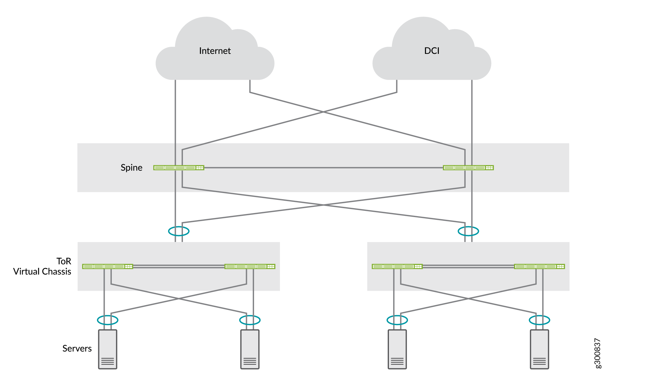
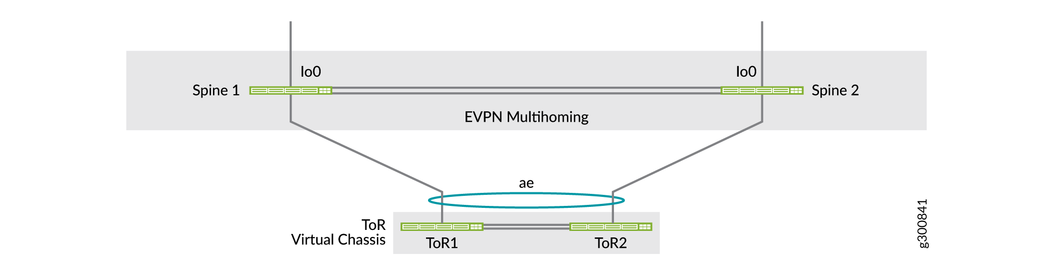
図 2 は、ToR レイヤーのバーチャル シャーシを、バックツーバックのコラプテッド スパイン レイヤーにマルチホームで配置し、スパイン デバイスが異なるバーチャル シャーシ メンバー スイッチにリンクして ESI-LAG の耐障害性を向上させます。
「 コラプテッドスパインとEVPNマルチホーミング」を参照してください。ネットワーク構成の例として、バックツーバックのスパインデバイスを使用したスパインの一般的な事例が説明されています。この例では、ToRデバイスは、折り畳まれたスパインデバイスにマルチホームされたバーチャルシャーシです。この例では、SRXシャーシクラスターを使用して追加のセキュリティサービスを設定してテナント間のトラフィックを保護し、データセンター間のトラフィックもSRXクラスターを介してDCIソリューションとしてルーティングする方法を示しています。
もう1つのコラプテッドスパインファブリックモデルは、折り畳まれたスパインコアアンダーレイおよびオーバーレイネットワークと統合するIPトランジットレイヤールートリフレクタクラスターを介してスパインデバイスを相互接続します。ジュニパーのリファレンス アーキテクチャでは、このモデルを使用し、以下のセクションで説明します。
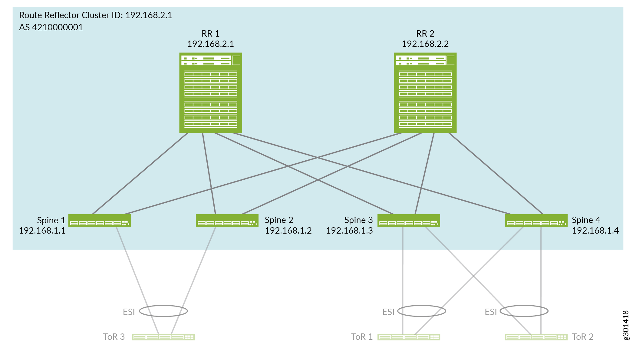
コラプテッドスパインリファレンスアーキテクチャの概要
ジュニパーのリファレンスアーキテクチャは、2つの納品ポイント間(POD)モジュールで構成されるコラプススパインデータセンターファブリックのユースケースを示しています。PODとコラプテッドスパインデバイスは、ルートリフレクタクラスタとして設定されたスーパースパインIPトランジットレイヤーで相互接続されます。 図 3 を参照してください。このアーキテクチャは、5ステージIPファブリック設計( 5ステージIPファブリックの設計と実装を参照)に似ていますが、スーパースパイン、スパイン、アクセスレイヤーのみです。折り畳み式スパインファブリックを設定して、ルートリフレクタクラスターデバイスを同様の方法でIPファブリックアンダーレイとEVPNオーバーレイに統合します。
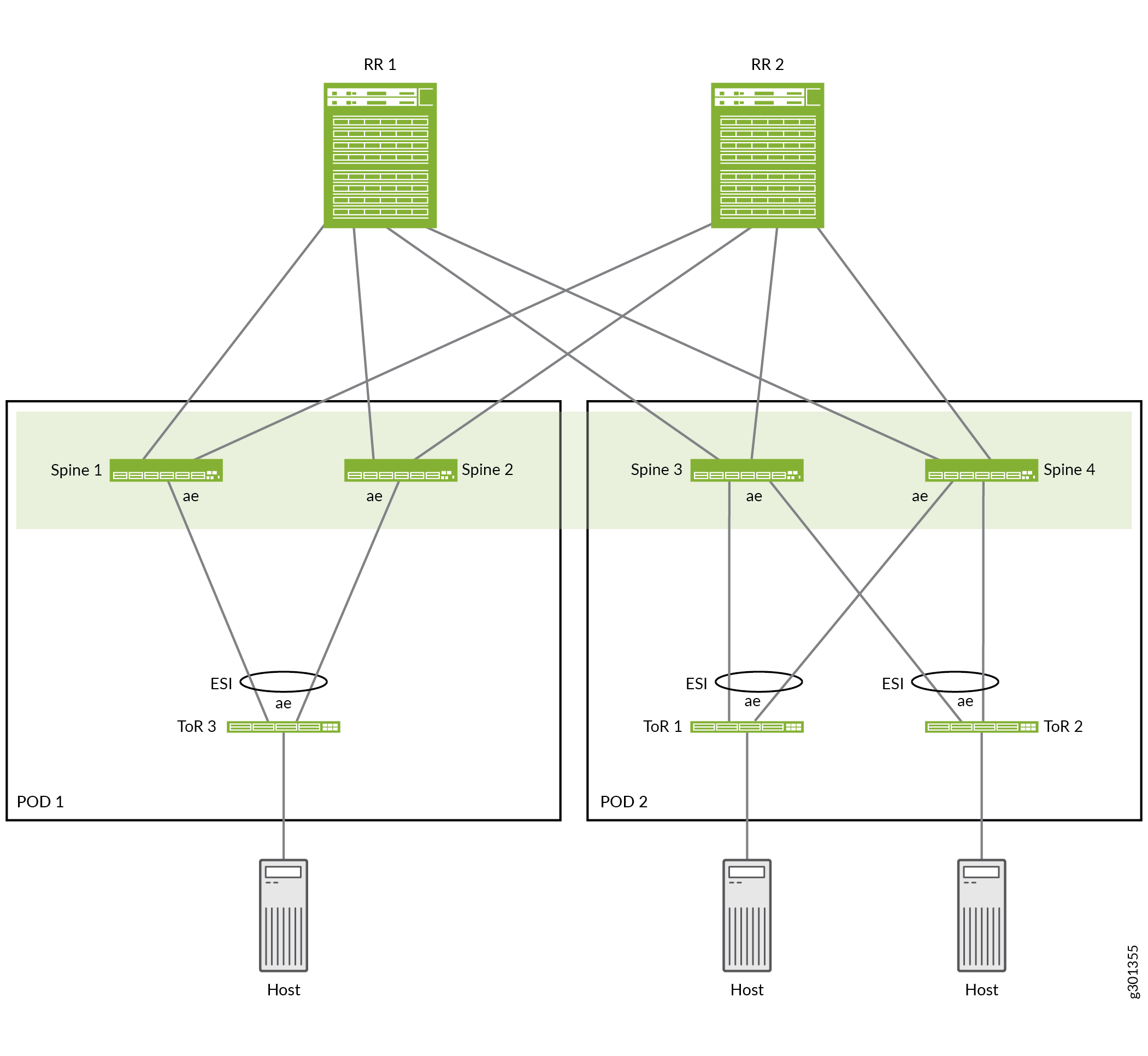
図3 は、以下の要素を含む折り畳まれたスパインリファレンスデザインの例を示しています。
POD 1:ToR 3はスパイン1とスパイン2にマルチホーム
POD 2:ToR 1および ToR 2は、スパイン3およびスパイン4にマルチホーム
ルートリフレクタクラスタ:スパインデバイス1~4を相互接続するRR1およびRR2
4つのスパインデバイスは、コラプテッドスパインEVPNファブリックコアを構成し、 2つのPODのスパインデバイス間でレイヤー2ストレッチとレイヤー3 ルーティングを行います。各PODのスパインデバイスは、同じPOD内のマルチホーム ToR スイッチに対して、ESI-LAGを使用します。
ルートリフレクタレイヤーと統合されたコラプテッドスパインIPファブリックアンダーレイを設定する
このセクションでは、スパインおよびルートリフレクタデバイス上で、相互接続リンクとIPファブリックアンダーレイを設定する方法について説明します。
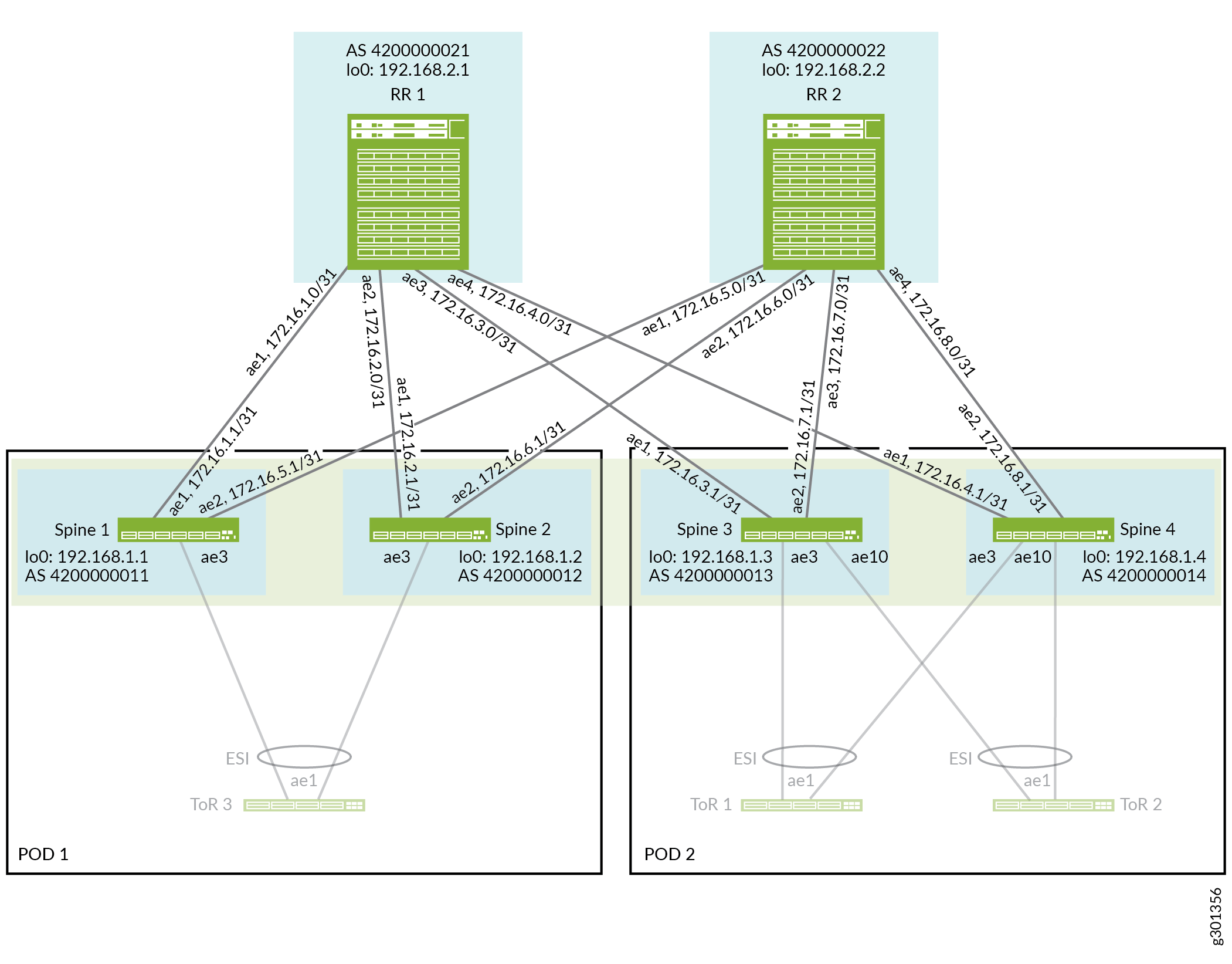
図4 は、集約されたイーサネットインターフェイスリンクで接続された折り畳み式スパインおよびルートリフレクタデバイスを示しています。
アンダーレイを設定するには:
- ファブリック内のルートリフレクタとスパインデバイスを接続するインターフェイスを設定する前に、それらの各デバイスで、デバイスに必要となる集約型イーサネットインターフェイスの数を設定する必要があります。デバイスは、設定した各集合型イーサネット インターフェイスに一意の MAC アドレスを割り当てます。
RR1、RR2 、スパイン1、スパイン2、 スパイン 3、およびスパ イン 4の集合型イーサネットインターフェイス数を 設定します。
set chassis aggregated-devices ethernet device-count 20
- 図4に示すように、折り畳まれたスパインファブリックを形成するルートリフレクタとスパインデバイス上の集合型イーサネットインターフェイスを設定します。
冗長性を確保するために、このリファレンスデザインでは、ルートリフレクタとスパインデバイス間の各集合型イーサネットリンクに2つの物理インターフェイスを使用します。ルートリフレクタデバイスは、 を介
ae4して集合型イーサネットインターフェイスを使用して4つのスパインデバイスにリンクしますae1。各スパインデバイスは、集約されたイーサネットインターフェイス(RR1へ)とae2(RR2 へ)を使用しますae1。また、物理インターフェイスに高いMTU(9192)を設定して、VXLANカプセル化を考慮します。
RR 1:
set interfaces et-0/0/46 ether-options 802.3ad ae1
set interfaces et-0/0/62 ether-options 802.3ad ae1

set interfaces et-0/0/9 ether-options 802.3ad ae2
set interfaces et-0/0/10 ether-options 802.3ad ae2

set interfaces et-0/0/49 ether-options 802.3ad ae3
set interfaces et-0/0/58 ether-options 802.3ad ae3

set interfaces xe-0/0/34:2 ether-options 802.3ad ae4
set interfaces xe-0/0/34:3 ether-options 802.3ad ae4

set interfaces ae1 mtu 9192
set interfaces ae1 aggregated-ether-options minimum-links 1
set interfaces ae1 aggregated-ether-options lacp active
set interfaces ae1 aggregated-ether-options lacp periodic fast
set interfaces ae1 unit 0 family inet address 172.16.1.0/31

set interfaces ae2 mtu 9192
set interfaces ae2 aggregated-ether-options minimum-links 1
set interfaces ae2 aggregated-ether-options lacp active
set interfaces ae2 aggregated-ether-options lacp periodic fast
set interfaces ae2 unit 0 family inet address 172.16.2.0/31

set interfaces ae3 mtu 9192
set interfaces ae3 aggregated-ether-options minimum-links 1
set interfaces ae3 aggregated-ether-options lacp active
set interfaces ae3 aggregated-ether-options lacp periodic fast
set interfaces ae3 unit 0 family inet address 172.16.3.0/31

set interfaces ae4 mtu 9192
set interfaces ae4 aggregated-ether-options minimum-links 1
set interfaces ae4 aggregated-ether-options lacp active
set interfaces ae4 aggregated-ether-options lacp periodic fast
set interfaces ae4 unit 0 family inet address 172.16.4.0/31
RR 2:
set interfaces et-0/0/18 ether-options 802.3ad ae1
set interfaces et-0/0/35 ether-options 802.3ad ae1

set interfaces et-0/0/13 ether-options 802.3ad ae2
set interfaces et-0/0/14 ether-options 802.3ad ae2

set interfaces et-0/0/22 ether-options 802.3ad ae3
set interfaces et-0/0/23 ether-options 802.3ad ae3

set interfaces et-0/0/19 ether-options 802.3ad ae4
set interfaces et-0/0/20 ether-options 802.3ad ae4

set interfaces ae1 mtu 9192
set interfaces ae1 aggregated-ether-options minimum-links 1
set interfaces ae1 aggregated-ether-options lacp active
set interfaces ae1 aggregated-ether-options lacp periodic fast
set interfaces ae1 unit 0 family inet address 172.16.5.0/31

set interfaces ae2 mtu 9192
set interfaces ae2 aggregated-ether-options minimum-links 1
set interfaces ae2 aggregated-ether-options lacp active
set interfaces ae2 aggregated-ether-options lacp periodic fast
set interfaces ae2 unit 0 family inet address 172.16.6.0/31

set interfaces ae3 mtu 9192
set interfaces ae3 aggregated-ether-options minimum-links 1
set interfaces ae3 aggregated-ether-options lacp active
set interfaces ae3 aggregated-ether-options lacp periodic fast
set interfaces ae3 unit 0 family inet address 172.16.7.0/31

set interfaces ae4 mtu 9192
set interfaces ae4 aggregated-ether-options minimum-links 1
set interfaces ae4 aggregated-ether-options lacp active
set interfaces ae4 aggregated-ether-options lacp periodic fast
set interfaces ae4 unit 0 family inet address 172.16.8.0/31
スパイン1:
set interfaces et-0/0/1 ether-options 802.3ad ae1
set interfaces et-0/0/2 ether-options 802.3ad ae1
set interfaces et-0/0/14 ether-options 802.3ad ae2
set interfaces et-0/0/27 ether-options 802.3ad ae2

set interfaces ae1 mtu 9192
set interfaces ae1 aggregated-ether-options minimum-links 1
set interfaces ae1 aggregated-ether-options lacp active
set interfaces ae1 aggregated-ether-options lacp periodic fast
set interfaces ae1 unit 0 family inet address 172.16.1.1/31

set interfaces ae2 mtu 9192
set interfaces ae2 aggregated-ether-options minimum-links 1
set interfaces ae2 aggregated-ether-options lacp active
set interfaces ae2 aggregated-ether-options lacp periodic fast
set interfaces ae2 unit 0 family inet address 172.16.5.1/31
スパイン2:
set interfaces et-0/0/1 ether-options 802.3ad ae1
set interfaces et-0/0/2 ether-options 802.3ad ae1

set interfaces et-0/0/14 ether-options 802.3ad ae2
set interfaces et-0/0/15 ether-options 802.3ad ae2

set interfaces ae1 mtu 9192
set interfaces ae1 aggregated-ether-options minimum-links 1
set interfaces ae1 aggregated-ether-options lacp active
set interfaces ae1 aggregated-ether-options lacp periodic fast
set interfaces ae1 unit 0 family inet address 172.16.2.1/31

set interfaces ae2 mtu 9192
set interfaces ae2 aggregated-ether-options minimum-links 1
set interfaces ae2 aggregated-ether-options lacp active
set interfaces ae2 aggregated-ether-options lacp periodic fast
set interfaces ae2 unit 0 family inet address 172.16.6.1/31
スパイン 3:
set interfaces et-0/0/0 ether-options 802.3ad ae1
set interfaces et-0/0/1 ether-options 802.3ad ae1

set interfaces et-0/0/7 ether-options 802.3ad ae2
set interfaces et-0/0/8 ether-options 802.3ad ae2

set interfaces ae1 mtu 9192
set interfaces ae1 aggregated-ether-options minimum-links 1
set interfaces ae1 aggregated-ether-options lacp active
set interfaces ae1 aggregated-ether-options lacp periodic fast
set interfaces ae1 unit 0 family inet address 172.16.3.1/31

set interfaces ae2 mtu 9192
set interfaces ae2 aggregated-ether-options minimum-links 1
set interfaces ae2 aggregated-ether-options lacp active
set interfaces ae2 aggregated-ether-options lacp periodic fast
set interfaces ae2 unit 0 family inet address 172.16.7.1/31
スパイン4:
set interfaces xe-0/0/3:2 ether-options 802.3ad ae1
set interfaces xe-0/0/3:3 ether-options 802.3ad ae1

set interfaces et-0/0/19 ether-options 802.3ad ae2
set interfaces et-0/0/20 ether-options 802.3ad ae2

set interfaces ae1 mtu 9192
set interfaces ae1 aggregated-ether-options minimum-links 1
set interfaces ae1 aggregated-ether-options lacp active
set interfaces ae1 aggregated-ether-options lacp periodic fast
set interfaces ae1 unit 0 family inet address 172.16.4.1/31

set interfaces ae2 mtu 9192
set interfaces ae2 aggregated-ether-options minimum-links 1
set interfaces ae2 aggregated-ether-options lacp active
set interfaces ae2 aggregated-ether-options lacp periodic fast
set interfaces ae2 unit 0 family inet address 172.16.8.1/31
- 図4に示すように、ループバックインターフェイスのIPアドレスと、各ルートリフレクタとスパインデバイスのルーターIDを設定します。
set interfaces lo0 unit 0 family inet address addr/32
set routing-options router-id addr
- ルートリフレクタとスパインデバイスで、EBGP IPファブリックアンダーレイを設定します。アンダーレイ構成は、 IPファブリックアンダーレイネットワークの設計と実装における他のスパイン/リーフリファレンスアーキテクチャ設計と類似しています。ただし、このリファレンスデザインのアンダーレイでは、コラプテッドスパインファブリックはルートリフレクタデバイスと統合され、POD内およびPOD間のスパインデバイス間でIPトランジット機能を果たします。
アンダーレイ構成には、次のものが含まれます。
EBGPピアリングデバイスにループバックインターフェイスのIPアドレスをアドバタイズするエクスポートルーティングポリシー(
underlay-clos-export)を定義します。このエクスポートルーティングポリシーは、各デバイスのループバックインターフェイスのIPアドレスを、IPファブリック内のすべてのデバイス(すべてのルートリフレクタとスパインデバイス)が到達可能にするために使用されます。各デバイスでローカルAS番号を定義します。
ルートリフレクタデバイス上:集約されたイーサネットリンクIPアドレスとローカルAS番号によって、4つのスパインデバイスをEBGPネイバーとして識別します。
スパインデバイス上:集約されたイーサネットリンクIPアドレスとローカルAS番号により、2つのルートリフレクタデバイスをEBGPネイバーとして識別します。
BGP ピア状態遷移ロギングを有効にします。
RR 1:
set protocols bgp group underlay-bgp type external

set policy-options policy-statement underlay-clos-export term loopback from interface lo0.0
set policy-options policy-statement underlay-clos-export term loopback then accept
set protocols bgp group underlay-bgp export underlay-clos-export

set protocols bgp group underlay-bgp local-as 4200000021
set protocols bgp group underlay-bgp multipath multiple-as

set protocols bgp group underlay-bgp neighbor 172.16.1.1 peer-as 4200000011
set protocols bgp group underlay-bgp neighbor 172.16.2.1 peer-as 4200000012
set protocols bgp group underlay-bgp neighbor 172.16.3.1 peer-as 4200000013
set protocols bgp group underlay-bgp neighbor 172.16.4.1 peer-as 4200000014
set protocols bgp log-updown
RR 2:
set protocols bgp group underlay-bgp type external

set policy-options policy-statement underlay-clos-export term loopback from interface lo0.0
set policy-options policy-statement underlay-clos-export term loopback then accept
set protocols bgp group underlay-bgp export underlay-clos-export

set protocols bgp group underlay-bgp local-as 4200000022
set protocols bgp group underlay-bgp multipath multiple-as

set protocols bgp group underlay-bgp neighbor 172.16.5.1 peer-as 4200000011
set protocols bgp group underlay-bgp neighbor 172.16.6.1 peer-as 4200000012
set protocols bgp group underlay-bgp neighbor 172.16.7.1 peer-as 4200000013
set protocols bgp group underlay-bgp neighbor 172.16.8.1 peer-as 4200000014
set protocols bgp log-updown
スパイン1:
set protocols bgp group underlay-bgp type external

set policy-options policy-statement underlay-clos-export term loopback from interface lo0.0
set policy-options policy-statement underlay-clos-export term loopback then accept
set protocols bgp group underlay-bgp export underlay-clos-export

set protocols bgp group underlay-bgp local-as 4200000011
set protocols bgp group underlay-bgp multipath multiple-as

set protocols bgp group underlay-bgp neighbor 172.16.1.0 peer-as 4200000021
set protocols bgp group underlay-bgp neighbor 172.16.5.0 peer-as 4200000022

set protocols bgp log-updown
スパイン2:
set protocols bgp group underlay-bgp type external

set policy-options policy-statement underlay-clos-export term loopback from interface lo0.0
set policy-options policy-statement underlay-clos-export term loopback then accept
set protocols bgp group underlay-bgp export underlay-clos-export

set protocols bgp group underlay-bgp local-as 4200000012
set protocols bgp group underlay-bgp multipath multiple-as

set protocols bgp group underlay-bgp neighbor 172.16.2.0 peer-as 4200000021
set protocols bgp group underlay-bgp neighbor 172.16.6.0 peer-as 4200000022

set protocols bgp log-updown
スパイン 3:
set protocols bgp group underlay-bgp type external

set policy-options policy-statement underlay-clos-export term loopback from interface lo0.0
set policy-options policy-statement underlay-clos-export term loopback then accept
set protocols bgp group underlay-bgp export underlay-clos-export

set protocols bgp group underlay-bgp local-as 4200000013
set protocols bgp group underlay-bgp multipath multiple-as

set protocols bgp group underlay-bgp neighbor 172.16.3.0 peer-as 4200000021
set protocols bgp group underlay-bgp neighbor 172.16.7.0 peer-as 4200000022

set protocols bgp log-updown
スパイン4:
set protocols bgp group underlay-bgp type external

set policy-options policy-statement underlay-clos-export term loopback from interface lo0.0
set policy-options policy-statement underlay-clos-export term loopback then accept
set protocols bgp group underlay-bgp export underlay-clos-export

set protocols bgp group underlay-bgp local-as 4200000014
set protocols bgp group underlay-bgp multipath multiple-as

set protocols bgp group underlay-bgp neighbor 172.16.4.0 peer-as 4200000021
set protocols bgp group underlay-bgp neighbor 172.16.8.0 peer-as 4200000022

set protocols bgp log-updown
ルートリフレクタレイヤーと統合された折り畳み式スパインEVPN-VXLANオーバーレイを設定する
この設計では、オーバーレイは他のEVPN-VXLANデータセンタースパインおよびリーフリファレンスアーキテクチャと似ていますが、リーフレイヤーは含まれておりません。ファブリックで VLAN 内ルーティングと VLAN 間ルーティングを行うのは、スパイン デバイス(ルート リフレクタ クラスタと統合)のみです。以下のように、スパインデバイス上に単一の自律システム(AS)番号を持つマルチプロトコルBGP(MP-IBGP)を使用してIBGPを設定し、ルートリフレクタクラスタデバイスを使用してそれらの間にシグナリングパスを確立します。
ルートリフレクタクラスタデバイスは、IPトランジット用の両方のPODのスパインデバイスとピアリングします。
スパインデバイスは、ルートリフレクタデバイスとピアリングします。
EVPNオーバーレイネットワークで設定するスパインおよびルートリフレクタクラスタデバイスとBGPネイバーIPアドレスを示した 図5を参照してください。
オーバーレイ設定は、デバイスのローカルアドレス(ループバックアドレス)を除き、ルートリフレクタデバイスの両方で同じです。ルートリフレクタデバイスは、すべてのスパインデバイスとピアリングします。
オーバーレイ設定は、デバイスのローカルアドレス(ループバックアドレス)を除いて、各スパインデバイスで同じです。すべてのスパインデバイスは、ルートリフレクタクラスタデバイスとピアリングします。
VXLAN カプセル化と VTEP(仮想トンネル エンドポイント)インターフェイスを、折り畳み式スパイン ファブリックのスパイン デバイスでのみ設定します。
オーバーレイを設定するには:
- すべてのスパインおよびルートリフレクタデバイスでIBGPオーバーレイのAS番号を設定します。
set routing-options autonomous-system 4210000001
- 図5に示すように、ルートリフレクタデバイスでEVPNシグナリングを使用してIBGPを設定し、折り畳まれたスパインデバイスとピアリングします。これは、デバイスのループバックアドレスによってIBGPネイバーとして識別されます。
このステップでは、以下も行います。
-
RR 1 および RR 2 をルート リフレクタ クラスタ(クラスタ ID 192.168.2.1)として定義します。
-
パスの最大送信単位(MTU)の検出を有効にして、送信元と宛先の間のネットワークパスのMTUサイズを動的に決定します。これは、IPフラグメント化を回避するのに役立ちます。
-
IBGP ネイバー障害を検出するための BFD(Bidirectional Forwarding Detection)を設定します。
-
デバイスが
vpn-apply-exportVPNルーティングテーブル内のルートを他のルートリフレクタまたはスパインデバイスにアドバタイズする前に、BGP設定内のVRFとBGPグループまたはネイバーエクスポートポリシーの両方が(その順序で)適用されていることを確認するために、 オプションを設定します。(詳細については、 VPNルートの配信 を参照してください)。
RR 1:
set protocols bgp group overlay-with-rr type internal
set protocols bgp group overlay-with-rr local-address 192.168.2.1

set protocols bgp group overlay-with-rr family evpn signaling

set protocols bgp group overlay-with-rr cluster 192.168.2.1
set protocols bgp group overlay-with-rr multipath
set protocols bgp group overlay-with-rr mtu-discovery

set protocols bgp group overlay-with-rr neighbor 192.168.1.1
set protocols bgp group overlay-with-rr neighbor 192.168.1.2
set protocols bgp group overlay-with-rr neighbor 192.168.1.3
set protocols bgp group overlay-with-rr neighbor 192.168.1.4

set protocols bgp group overlay-with-rr bfd-liveness-detection minimum-interval 1000
set protocols bgp group overlay-with-rr bfd-liveness-detection multiplier 3
set protocols bgp group overlay-with-rr bfd-liveness-detection session-mode automatic

set protocols bgp group overlay-with-rr vpn-apply-export
RR 2:
set protocols bgp group overlay-with-rr type internal
set protocols bgp group overlay-with-rr local-address 192.168.2.2

set protocols bgp group overlay-with-rr family evpn signaling

set protocols bgp group overlay-with-rr cluster 192.168.2.1
set protocols bgp group overlay-with-rr multipath
set protocols bgp group overlay-with-rr mtu-discovery

set protocols bgp group overlay-with-rr neighbor 192.168.1.1
set protocols bgp group overlay-with-rr neighbor 192.168.1.2
set protocols bgp group overlay-with-rr neighbor 192.168.1.3
set protocols bgp group overlay-with-rr neighbor 192.168.1.4

set protocols bgp group overlay-with-rr bfd-liveness-detection minimum-interval 1000
set protocols bgp group overlay-with-rr bfd-liveness-detection multiplier 3
set protocols bgp group overlay-with-rr bfd-liveness-detection session-mode automatic

set protocols bgp group overlay-with-rr vpn-apply-export
-
- 折り畳み式スパインデバイス上でEVPNを使用してIBGPを設定し、ルートリフレクタデバイスとピアリングします。これは図5に示すデバイスループバックアドレスによってIBGPネイバーとして識別されます。スパインデバイスのループバックIPアドレスを値に置き換える以外は、すべてのスパインデバイスで設定は
local-address device-loopback-addr同じです。このステップでは、次のことも行います。
-
パスの最大送信単位(MTU)の検出を有効にして、送信元と宛先の間のネットワークパスのMTUサイズを動的に決定します。これは、IPフラグメント化を回避するのに役立ちます。
-
IBGP ネイバー障害を検出するための BFD を設定します。
-
デバイスが
vpn-apply-exportVPNルーティングテーブル内のルートを他のルートリフレクタまたはスパインデバイスにアドバタイズする前に、BGP設定内のVRFとBGPグループまたはネイバーエクスポートポリシーの両方が(その順序で)適用されていることを確認するために、 オプションを設定します。(詳細については、 VPNルートの配信 を参照してください)。
すべてのスパインデバイス:
set protocols bgp group overlay-with-rr type internal
set protocols bgp group overlay-with-rr local-address device-loopback-addr

set protocols bgp group overlay-with-rr family evpn signaling

set protocols bgp group overlay-with-rr multipath
set protocols bgp group overlay-with-rr mtu-discovery

set protocols bgp group overlay-with-rr neighbor 192.168.2.1
set protocols bgp group overlay-with-rr neighbor 192.168.2.2

set protocols bgp group overlay-with-rr bfd-liveness-detection minimum-interval 1000
set protocols bgp group overlay-with-rr bfd-liveness-detection multiplier 3
set protocols bgp group overlay-with-rr bfd-liveness-detection session-mode automatic

set protocols bgp group overlay-with-rr vpn-apply-export
-
- ルートリフレクタクラスタとスパインデバイスの管理インターフェイス(
em0)を除くすべてのインターフェイスでLLDPが有効になっていることを確認します。すべてのルートリフレクタとスパインデバイス:
set protocols lldp interface all
set protocols lldp interface em0 disable
- スパインデバイス上のオーバーレイにVXLANカプセル化を使用してEVPNを設定します。この設定は、コラプテッドスパインファブリック内のすべてのスパインデバイスで同じです。
このステップでは、以下を実行します。
-
転送テーブルで ECMP のパケット単位のロード バランシングに関するポリシーを指定し、適用します。
-
[edit protocols evpn]階層レベルで以下のEVPNオプションを設定し、VXLANカプセル化を設定します。
-
default-gateway no-gateway-community:仮想ゲートウェイと IRB MAC アドレスを EVPN ピア デバイスにアドバタイズし、イーサネット専用エッジ デバイスがこれらの MAC アドレスを学習できるようにします。スパインが以下を使用する場合、コラプテッドスパインファブリックで設定no-gateway-communityします。-
ゲートウェイとしてのエニキャスト IP、または共通のエニキャスト MAC アドレスを持つ
-
VRRP ベースの MAC アドレスを持つ仮想ゲートウェイ アドレス(00:00:5e:00:01:XX)(ToR スイッチのスパイン デバイス上の EVPN マルチホーミングと仮想ネットワークの設定のステップ 5 を参照してください。
-
-
extended-vni-list allオプション:設定されたすべてのVXLANネットワーク識別子(VNI)がこのEVPN-VXLAN BGPドメインの一部になることを許可します。後のセクションでVLANとVLANからVNIへのマッピングを設定します。 -
remote-ip-host-routes:VMTO(仮想マシン トラフィックの最適化)を有効にします。(詳細については、「 Ingress Virtual Machine Traffic Optimization for EVPN」 を参照してください)。
-
すべてのスパインデバイス:
set policy-options policy-statement per-packet-load-balance term 1 then load-balance per-packet
set routing-options forwarding-table export per-packet-load-balance

set protocols evpn encapsulation vxlan
set protocols evpn default-gateway no-gateway-community
set protocols evpn extended-vni-list all
set protocols evpn remote-ip-host-routes
-
- スパインデバイスでVTEP、ルートターゲット、VRF(仮想ルーティングおよび転送)スイッチオプションを設定します。
設定は、デバイスのループバックIPアドレスを値に置き換える各デバイスを除き、すべてのスパインデバイスで
route-distinguisher同じです。この値は、各デバイスによって生成されたルートの一意のルート識別を定義します。EVPNインスタンスのVTEP送信元インターフェイスも、IBGPローカルピアアドレス(同様にデバイスループバックIPアドレス)と一致する必要があります。
スパイン1:
set switch-options vtep-source-interface lo0.0
set switch-options route-distinguisher 192.168.1.1:3333
set switch-options vrf-target target:10458:0
set switch-options vrf-target auto
スパイン2:
set switch-options vtep-source-interface lo0.0
set switch-options route-distinguisher 192.168.1.2:3333
set switch-options vrf-target target:10458:0
set switch-options vrf-target auto
スパイン 3:
set switch-options vtep-source-interface lo0.0
set switch-options route-distinguisher 192.168.1.3:3333
set switch-options vrf-target target:10458:0
set switch-options vrf-target auto
スパイン4:
set switch-options vtep-source-interface lo0.0
set switch-options route-distinguisher 192.168.1.4:3333
set switch-options vrf-target target:10458:0
set switch-options vrf-target auto
- (PTX10000 シリーズ ルーターでのみ必要)デバイス上でグローバル(つまり、すべてのインターフェイス)でトンネルの終端を有効にします。
set forwarding-options tunnel-termination
ToRスイッチのスパインデバイスでEVPNマルチホーミングと仮想ネットワークを設定する
このコラプテッドスパインリファレンス設計は、 イーサネット接続されたエンドシステムの設計と実装のマルチホーミングで説明されているように、EVPNマルチホーミングを実装します。ただし、リーフ層の機能はスパインレイヤーに集約されるため、スパインデバイスにESI-LAGを設定する必要があります。また、VLANとレイヤー2 およびレイヤー3 のルーティング機能は、エッジルーティングブリッジング(ERB)オーバーレイ設計のリーフデバイスと同様の方法でスパインデバイス上で設定します。コアのコラプテッドスパイン構成では、両方のPOD内のすべてのスパインデバイスに同じVLAN(およびVLANからVNIマッピング)を設定することで、レイヤー2 ストレッチを実装します。EVPNタイプ 2ルートは、POD内およびPOD間のエンドポイント間の通信を可能にします。
図6 は、POD内のマルチホーム ToR スイッチへの集約型イーサネットインターフェイスリンクで接続された各PODのコラプテッドスパインデバイスを示しています。
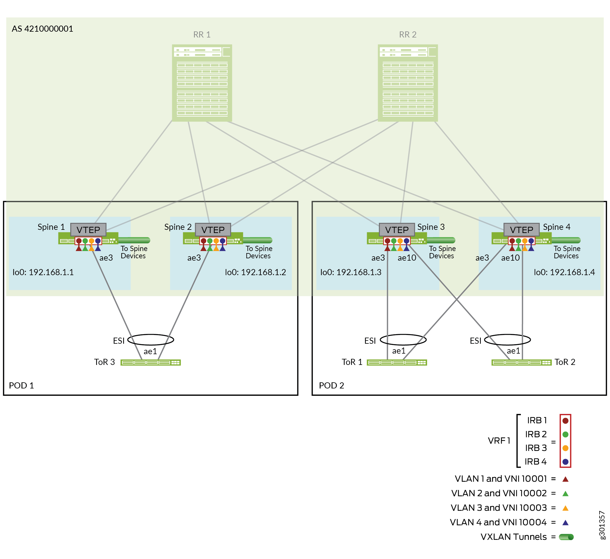
簡潔にするために、このセクションでは、各スパインと各 ToR デバイスの間に 1 つの集合型イーサネット リンクを示し、スパイン デバイスから POD 内の ToR デバイスへの各集合型イーサネット リンクに 1 つのインターフェイスが設定されています。
このセクションでは、POD 2のスパインおよび ToR デバイスの設定の詳細について説明します。適用可能なデバイスパラメータとインターフェイスを使用して、ポッド 1のスパインおよび ToR デバイスに同様の設定を適用できます。
ToRデバイスには、マルチホーミング用のESI-LAGを形成するPOD内の各スパインデバイスに1つずつ、集約されたイーサネットリンクに2つのインターフェイスが含まれています。
この構成には、以下の手順が含まれています。
インターフェイスを設定します。
EVPN マルチホーミング用に ESI-LAG を設定します。
VLAN の定義、VLAN 間ルーティング用の関連 IRB インターフェイス、対応する VLAN から VNI へのマッピングなど、レイヤー 2 およびレイヤー 3 ゲートウェイ機能を設定します。
- ポッド 2のマルチホーム ToR スイッチ(ToR 1および ToR 2)へのスパイン(スパイン 3およびスパイン 4)上のインターフェイスと集合型イーサネットリンクを設定します。
スパイン 3:
set interfaces xe-0/0/22:0 hold-time up 450000
set interfaces xe-0/0/22:0 hold-time down 450000
set interfaces xe-0/0/22:0 ether-options 802.3ad ae3

set interfaces xe-0/0/23:0 hold-time up 450000
set interfaces xe-0/0/23:0 hold-time down 450000
set interfaces xe-0/0/23:0 ether-options 802.3ad ae10
スパイン4:
set interfaces xe-0/0/4:2 hold-time up 450000
set interfaces xe-0/0/4:2 hold-time down 450000
set interfaces xe-0/0/4:2 ether-options 802.3ad ae3

set interfaces xe-0/0/6:1 hold-time up 450000
set interfaces xe-0/0/6:1 hold-time down 450000
set interfaces xe-0/0/6:1 ether-options 802.3ad ae10
- POD 2のマルチホーム ToR スイッチのスパインデバイス上で、EVPNマルチホーミング用のESI-LAGを設定します。この設計では、ToRスイッチにスパインデバイス上で同じ集合型イーサネットインターフェイスを使用するため、両方のデバイスで同じ設定を使用します。
このリファレンスデザインでは、
ae3ToR 1に接続し、ae10ToR 2に接続します。スパイン3およびスパイン4:
set interfaces ae3 esi 00:00:00:ff:00:02:00:01:00:03
set interfaces ae3 esi all-active
set interfaces ae3 aggregated-ether-options lacp active
set interfaces ae3 aggregated-ether-options lacp periodic fast
set interfaces ae3 aggregated-ether-options lacp system-id 00:00:00:99:99:01
set interfaces ae3 aggregated-ether-options lacp hold-time up 300

set interfaces ae10 esi 00:00:00:ff:00:01:00:01:00:0a
set interfaces ae10 esi all-active
set interfaces ae10 aggregated-ether-options lacp active
set interfaces ae10 aggregated-ether-options lacp periodic fast
set interfaces ae10 aggregated-ether-options lacp system-id 00:00:00:99:99:01
set interfaces ae10 aggregated-ether-options lacp hold-time up 300
- VLANメンバーととして、POD2 のスパインデバイス上の
ae10ae3VLANを設定します。スパイン3およびスパイン4:
set interfaces ae3 native-vlan-id 4094
set interfaces ae3 unit 0 family ethernet-switching interface-mode trunk
set interfaces ae3 unit 0 family ethernet-switching vlan members VLAN-1
set interfaces ae3 unit 0 family ethernet-switching vlan members VLAN-2
set interfaces ae3 unit 0 family ethernet-switching vlan members VLAN-3
set interfaces ae3 unit 0 family ethernet-switching vlan members VLAN-4

set interfaces ae10 native-vlan-id 4094
set interfaces ae10 unit 0 family ethernet-switching interface-mode trunk
set interfaces ae10 unit 0 family ethernet-switching vlan members VLAN-1
set interfaces ae10 unit 0 family ethernet-switching vlan members VLAN-2
set interfaces ae10 unit 0 family ethernet-switching vlan members VLAN-3
set interfaces ae10 unit 0 family ethernet-switching vlan members VLAN-4
- VXLAN トンネルの VLAN を VNI にマッピングし、各トンネルに IRB インターフェイスを関連付けます。
スパイン3およびスパイン4:
set vlans VLAN-1 vlan-id 1
set vlans VLAN-1 l3-interface irb.1
set vlans VLAN-1 vxlan vni 100001
set vlans VLAN-2 vlan-id 2
set vlans VLAN-2 l3-interface irb.2
set vlans VLAN-2 vxlan vni 100002
set vlans VLAN-3 vlan-id 3
set vlans VLAN-3 l3-interface irb.3
set vlans VLAN-3 vxlan vni 100003
set vlans VLAN-4 vlan-id 4
set vlans VLAN-4 l3-interface irb.4
set vlans VLAN-4 vxlan vni 100004
- IRB IPアドレスと仮想ゲートウェイIPアドレスの両方に対して、IPv4およびIPv6デュアルスタックアドレスを持つPOD 2のスパインデバイス上のVNI(VLAN)のIRBインターフェイスを設定します。
スパイン 3:
set interfaces irb unit 1 virtual-gateway-accept-data
set interfaces irb unit 1 family inet address 10.0.1.243/24 preferred
set interfaces irb unit 1 family inet address 10.0.1.243/24 virtual-gateway-address 10.0.1.254
set interfaces irb unit 1 family inet6 nd6-stale-time 3600
set interfaces irb unit 1 family inet6 address 2001:db8::10:0:1:243/112 preferred
set interfaces irb unit 1 family inet6 address 2001:db8::10:0:1:243/112 virtual-gateway-address 2001:db8::10:0:1:254
set interfaces irb unit 1 virtual-gateway-v4-mac 00:00:5e:00:00:04
set interfaces irb unit 1 virtual-gateway-v6-mac 00:00:5e:00:00:04

set interfaces irb unit 2 virtual-gateway-accept-data
set interfaces irb unit 2 family inet address 10.0.2.243/24 preferred
set interfaces irb unit 2 family inet address 10.0.2.243/24 virtual-gateway-address 10.0.2.254
set interfaces irb unit 2 family inet6 nd6-stale-time 3600
set interfaces irb unit 2 family inet6 address 2001:db8::10:0:2:243/112 preferred
set interfaces irb unit 2 family inet6 address 2001:db8::10:0:2:243/112 virtual-gateway-address 2001:db8::10:0:2:254
set interfaces irb unit 2 virtual-gateway-v4-mac 00:00:5e:00:00:04
set interfaces irb unit 2 virtual-gateway-v6-mac 00:00:5e:00:00:04

set interfaces irb unit 3 virtual-gateway-accept-data
set interfaces irb unit 3 family inet address 10.0.3.243/24 preferred
set interfaces irb unit 3 family inet address 10.0.3.243/24 virtual-gateway-address 10.0.3.254
set interfaces irb unit 3 family inet6 nd6-stale-time 3600
set interfaces irb unit 3 family inet6 address 2001:db8::10:0:3:243/112 preferred
set interfaces irb unit 3 family inet6 address 2001:db8::10:0:3:243/112 virtual-gateway-address 2001:db8::10:0:3:254
set interfaces irb unit 3 virtual-gateway-v4-mac 00:00:5e:00:00:04
set interfaces irb unit 3 virtual-gateway-v6-mac 00:00:5e:00:00:04

set interfaces irb unit 4 virtual-gateway-accept-data
set interfaces irb unit 4 family inet address 10.0.4.243/24 preferred
set interfaces irb unit 4 family inet address 10.0.4.243/24 virtual-gateway-address 10.0.4.254
set interfaces irb unit 4 family inet6 nd6-stale-time 3600
set interfaces irb unit 4 family inet6 address 2001:db8::10:0:4:243/112 preferred
set interfaces irb unit 4 family inet6 address 2001:db8::10:0:4:243/112 virtual-gateway-address 2001:db8::10:0:4:254
set interfaces irb unit 4 virtual-gateway-v4-mac 00:00:5e:00:00:04
set interfaces irb unit 4 virtual-gateway-v6-mac 00:00:5e:00:00:04
スパイン4:
set interfaces irb unit 1 virtual-gateway-accept-data
set interfaces irb unit 1 family inet address 10.0.1.244/24 preferred
set interfaces irb unit 1 family inet address 10.0.1.244/24 virtual-gateway-address 10.0.1.254
set interfaces irb unit 1 family inet6 nd6-stale-time 3600
set interfaces irb unit 1 family inet6 address 2001:db8::10:0:1:244/112 preferred
set interfaces irb unit 1 family inet6 address 2001:db8::10:0:1:244/112 virtual-gateway-address 2001:db8::10:0:1:254
set interfaces irb unit 1 virtual-gateway-v4-mac 00:00:5e:00:00:04
set interfaces irb unit 1 virtual-gateway-v6-mac 00:00:5e:00:00:04

set interfaces irb unit 2 virtual-gateway-accept-data
set interfaces irb unit 2 family inet address 10.0.2.244/24 preferred
set interfaces irb unit 2 family inet address 10.0.2.244/24 virtual-gateway-address 10.0.2.254
set interfaces irb unit 2 family inet6 nd6-stale-time 3600
set interfaces irb unit 2 family inet6 address 2001:db8::10:0:2:244/112 preferred
set interfaces irb unit 2 family inet6 address 2001:db8::10:0:2:244/112 virtual-gateway-address 2001:db8::10:0:2:254
set interfaces irb unit 2 virtual-gateway-v4-mac 00:00:5e:00:00:04
set interfaces irb unit 2 virtual-gateway-v6-mac 00:00:5e:00:00:04

set interfaces irb unit 3 virtual-gateway-accept-data
set interfaces irb unit 3 family inet address 10.0.3.244/24 preferred
set interfaces irb unit 3 family inet address 10.0.3.244/24 virtual-gateway-address 10.0.3.254
set interfaces irb unit 3 family inet6 nd6-stale-time 3600
set interfaces irb unit 3 family inet6 address 2001:db8::10:0:3:244/112 preferred
set interfaces irb unit 3 family inet6 address 2001:db8::10:0:3:244/112 virtual-gateway-address 2001:db8::10:0:3:254
set interfaces irb unit 3 virtual-gateway-v4-mac 00:00:5e:00:00:04
set interfaces irb unit 3 virtual-gateway-v6-mac 00:00:5e:00:00:04

set interfaces irb unit 4 virtual-gateway-accept-data
set interfaces irb unit 4 family inet address 10.0.4.244/24 preferred
set interfaces irb unit 4 family inet address 10.0.4.244/24 virtual-gateway-address 10.0.4.254
set interfaces irb unit 4 family inet6 nd6-stale-time 3600
set interfaces irb unit 4 family inet6 address 2001:db8::10:0:4:244/112 preferred
set interfaces irb unit 4 family inet6 address 2001:db8::10:0:4:244/112 virtual-gateway-address 2001:db8::10:0:4:254
set interfaces irb unit 4 virtual-gateway-v4-mac 00:00:5e:00:00:04
set interfaces irb unit 4 virtual-gateway-v6-mac 00:00:5e:00:00:04
- 設定されたVLAN(VNI)に対して、POD 2の各スパインデバイス上のEVPNタイプ 2ルートのVRFルーティングインスタンスと対応するIRBインターフェイスを定義します。
スパイン 3:
set interfaces lo0 unit 1 family inet

set routing-instances VRF-T2-1 instance-type vrf
set routing-instances VRF-T2-1 interface lo0.1
set routing-instances VRF-T2-1 interface irb.1
set routing-instances VRF-T2-1 interface irb.2
set routing-instances VRF-T2-1 interface irb.3
set routing-instances VRF-T2-1 interface irb.4
set routing-instances VRF-T2-1 route-distinguisher 192.168.1.3:1
set routing-instances VRF-T2-1 vrf-target target:100:1
スパイン4:
set interfaces lo0 unit 1 family inet

set routing-instances VRF-T2-1 instance-type vrf
set routing-instances VRF-T2-1 interface lo0.1
set routing-instances VRF-T2-1 interface irb.1
set routing-instances VRF-T2-1 interface irb.2
set routing-instances VRF-T2-1 interface irb.3
set routing-instances VRF-T2-1 interface irb.4
set routing-instances VRF-T2-1 route-distinguisher 192.168.1.4:1
set routing-instances VRF-T2-1 vrf-target target:100:1
- マルチホーム ToR スイッチ(ToR 1 および ToR 2)上のインターフェイスと集合型イーサネット リンクを POD 2 のスパイン デバイス(スパイン 3 およびスパイン 4)に設定します。このステップでは、次の手順に進みます。
必要となる可能性があるスイッチ上の集合型イーサネット インターフェイスの数を設定します(ここでは 20 を例に設定します)。
各 ToR スイッチ上の集合型イーサネット リンク
ae1を POD 2 のスパイン デバイスに設定します。インターフェイスにLLDPを設定します。
ToR 1:
set chassis aggregated-devices ethernet device-count 20

set interfaces xe-0/0/26 ether-options 802.3ad ae1
set interfaces xe-0/0/27 ether-options 802.3ad ae1

set interfaces ae1 aggregated-ether-options minimum-links 1
set interfaces ae1 aggregated-ether-options lacp active
set interfaces ae1 aggregated-ether-options lacp periodic fast

set protocols lldp interface all
set protocols lldp interface em0 disable
ToR 2:
set chassis aggregated-devices ethernet device-count 20

set interfaces xe-0/0/1 ether-options 802.3ad ae1
set interfaces xe-0/0/27 ether-options 802.3ad ae1

set interfaces ae1 aggregated-ether-options minimum-links 1
set interfaces ae1 aggregated-ether-options lacp active
set interfaces ae1 aggregated-ether-options lacp periodic fast

set protocols lldp interface all
set protocols lldp interface em0 disable
- POD 2の ToR スイッチで VLAN を設定します。これらは、POD 2のスパインデバイスのステップ 3 で設定したVLANと一致します 。
ToR 1 および ToR 2:
set vlans VLAN-1 vlan-id 1
set vlans VLAN-2 vlan-id 2
set vlans VLAN-3 vlan-id 3
set vlans VLAN-4 vlan-id 4

set interfaces ae1 native-vlan-id 4094
set interfaces ae1 unit 0 family ethernet-switching interface-mode trunk
set interfaces ae1 unit 0 family ethernet-switching vlan members VLAN-1
set interfaces ae1 unit 0 family ethernet-switching vlan members VLAN-2
set interfaces ae1 unit 0 family ethernet-switching vlan members VLAN-3
set interfaces ae1 unit 0 family ethernet-switching vlan members VLAN-4
ルートリフレクタクラスタおよび ToR デバイスによる折り畳み式スパインファブリック接続の検証
このセクションでは、コラプテッドスパインデバイスとルートリフレクタクラスタ間、およびコラプテッドスパインデバイスと ToR デバイス間の接続を検証するために使用できるCLIコマンドを示します。
簡潔にするために、このセクションではPOD 2のスパイン3とスパイン4のみを使用して、スパイン デバイス上の接続を検証します。ポッド 1のスパインデバイス(スパイン1およびスパイン 2)で同じコマンドを使用できます。
- 4つの折り畳み式スパインデバイスに向かうルートリフレクタデバイス上の集合型イーサネットリンク上の接続を検証します。各ルートリフレクタデバイスで、
aeXスパイン Xに接続します)。RR 1:
user@rr-1> show lacp interfaces
Aggregated interface: ae1
    LACP state:       Role   Exp   Def  Dist  Col  Syn  Aggr  Timeout  Activity
      et-0/0/46      Actor    No    No   Yes  Yes  Yes   Yes     Fast    Active
      et-0/0/46    Partner    No    No   Yes  Yes  Yes   Yes     Fast    Active
      et-0/0/62      Actor    No    No   Yes  Yes  Yes   Yes     Fast    Active
      et-0/0/62    Partner    No    No   Yes  Yes  Yes   Yes     Fast    Active
    LACP protocol:        Receive State  Transmit State          Mux State
      et-0/0/46                 Current   Fast periodic Collecting distributing
      et-0/0/62                 Current   Fast periodic Collecting distributing


Aggregated interface: ae2
    LACP state:       Role   Exp   Def  Dist  Col  Syn  Aggr  Timeout  Activity
      et-0/0/9      Actor    No    No   Yes  Yes  Yes   Yes     Fast    Active
      et-0/0/9    Partner    No    No   Yes  Yes  Yes   Yes     Fast    Active
      et-0/0/10     Actor    No    No   Yes  Yes  Yes   Yes     Fast    Active
      et-0/0/10    Partner    No    No   Yes  Yes  Yes   Yes     Fast    Active
    LACP protocol:        Receive State  Transmit State          Mux State
      et-0/0/9                  Current   Fast periodic Collecting distributing
      et-0/0/10                 Current   Fast periodic Collecting distributing


Aggregated interface: ae3
    LACP state:       Role   Exp   Def  Dist  Col  Syn  Aggr  Timeout  Activity
      et-0/0/49      Actor    No    No   Yes  Yes  Yes   Yes     Fast    Active
      et-0/0/49    Partner    No    No   Yes  Yes  Yes   Yes     Fast    Active
      et-0/0/58      Actor    No    No   Yes  Yes  Yes   Yes     Fast    Active
      et-0/0/58    Partner    No    No   Yes  Yes  Yes   Yes     Fast    Active
    LACP protocol:        Receive State  Transmit State          Mux State
      et-0/0/49                 Current   Fast periodic Collecting distributing
      et-0/0/58                 Current   Fast periodic Collecting distributing


Aggregated interface: ae4
    LACP state:       Role   Exp   Def  Dist  Col  Syn  Aggr  Timeout  Activity
      xe-0/0/34:2    Actor    No    No   Yes  Yes  Yes   Yes     Fast    Active
      xe-0/0/34:2  Partner    No    No   Yes  Yes  Yes   Yes     Fast    Active
      xe-0/0/34:3    Actor    No    No   Yes  Yes  Yes   Yes     Fast    Active
      xe-0/0/34:3  Partner    No    No   Yes  Yes  Yes   Yes     Fast    Active
    LACP protocol:        Receive State  Transmit State          Mux State
      xe-0/0/34:2               Current   Fast periodic Collecting distributing
      xe-0/0/34:3               Current   Fast periodic Collecting distributing
RR 2:
user@rr-2> show lacp interfaces Aggregated interface: ae1 LACP state: Role Exp Def Dist Col Syn Aggr Timeout Activity et-0/0/18 Actor No No Yes Yes Yes Yes Fast Active et-0/0/18 Partner No No Yes Yes Yes Yes Fast Active et-0/0/35 Actor No No Yes Yes Yes Yes Fast Active et-0/0/35 Partner No No Yes Yes Yes Yes Fast Active LACP protocol: Receive State Transmit State Mux State et-0/0/18 Current Fast periodic Collecting distributing et-0/0/35 Current Fast periodic Collecting distributing Aggregated interface: ae2 LACP state: Role Exp Def Dist Col Syn Aggr Timeout Activity et-0/0/13 Actor No No Yes Yes Yes Yes Fast Active et-0/0/13 Partner No No Yes Yes Yes Yes Fast Active et-0/0/14 Actor No No Yes Yes Yes Yes Fast Active et-0/0/14 Partner No No Yes Yes Yes Yes Fast Active LACP protocol: Receive State Transmit State Mux State et-0/0/13 Current Fast periodic Collecting distributing et-0/0/14 Current Fast periodic Collecting distributing Aggregated interface: ae3 LACP state: Role Exp Def Dist Col Syn Aggr Timeout Activity et-0/0/22 Actor No No Yes Yes Yes Yes Fast Active et-0/0/22 Partner No No Yes Yes Yes Yes Fast Active et-0/0/23 Actor No No Yes Yes Yes Yes Fast Active et-0/0/23 Partner No No Yes Yes Yes Yes Fast Active LACP protocol: Receive State Transmit State Mux State et-0/0/22 Current Fast periodic Collecting distributing et-0/0/23 Current Fast periodic Collecting distributing Aggregated interface: ae4 LACP state: Role Exp Def Dist Col Syn Aggr Timeout Activity et-0/0/19 Actor No No Yes Yes Yes Yes Fast Active et-0/0/19 Partner No No Yes Yes Yes Yes Fast Active et-0/0/20 Actor No No Yes Yes Yes Yes Fast Active et-0/0/20 Partner No No Yes Yes Yes Yes Fast Active LACP protocol: Receive State Transmit State Mux State et-0/0/19 Current Fast periodic Collecting distributing et-0/0/20 Current Fast periodic Collecting distributing - ルートリフレクタデバイスに向けたPOD 2(スパイン3およびスパイン4)のスパイン デバイス上の集合型イーサネットリンク上の接続を確認します。
ae1およびは、スパイン3とae2スパイン 4の両方で、それぞれルートリフレクタデバイスRR1 およびRR2 に接続します。スパイン 3:
user@spine-3> show lacp interfaces ae1
Aggregated interface: ae1
    LACP state:       Role   Exp   Def  Dist  Col  Syn  Aggr  Timeout  Activity
      et-0/0/0       Actor    No    No   Yes  Yes  Yes   Yes     Fast    Active
      et-0/0/0     Partner    No    No   Yes  Yes  Yes   Yes     Fast    Active
      et-0/0/1       Actor    No    No   Yes  Yes  Yes   Yes     Fast    Active
      et-0/0/1     Partner    No    No   Yes  Yes  Yes   Yes     Fast    Active
    LACP protocol:        Receive State  Transmit State          Mux State
      et-0/0/0                  Current   Fast periodic Collecting distributing
      et-0/0/1                  Current   Fast periodic Collecting distributing


user@spine-3> show lacp interfaces ae2
Aggregated interface: ae2
    LACP state:       Role   Exp   Def  Dist  Col  Syn  Aggr  Timeout  Activity
      et-0/0/7       Actor    No    No   Yes  Yes  Yes   Yes     Fast    Active
      et-0/0/7     Partner    No    No   Yes  Yes  Yes   Yes     Fast    Active
      et-0/0/8       Actor    No    No   Yes  Yes  Yes   Yes     Fast    Active
      et-0/0/8     Partner    No    No   Yes  Yes  Yes   Yes     Fast    Active
    LACP protocol:        Receive State  Transmit State          Mux State
      et-0/0/7                  Current   Fast periodic Collecting distributing
      et-0/0/8                  Current   Fast periodic Collecting distributing
スパイン4:
user@spine-4> show lacp interfaces ae1 Aggregated interface: ae1 LACP state: Role Exp Def Dist Col Syn Aggr Timeout Activity xe-0/0/3:2 Actor No No Yes Yes Yes Yes Fast Active xe-0/0/3:2 Partner No No Yes Yes Yes Yes Fast Active xe-0/0/3:3 Actor No No Yes Yes Yes Yes Fast Active xe-0/0/3:3 Partner No No Yes Yes Yes Yes Fast Active LACP protocol: Receive State Transmit State Mux State xe-0/0/3:2 Current Fast periodic Collecting distributing xe-0/0/3:3 Current Fast periodic Collecting distributing user@spine-4> show lacp interfaces ae2 Aggregated interface: ae2 LACP state: Role Exp Def Dist Col Syn Aggr Timeout Activity et-0/0/19 Actor No No Yes Yes Yes Yes Fast Active et-0/0/19 Partner No No Yes Yes Yes Yes Fast Active et-0/0/20 Actor No No Yes Yes Yes Yes Fast Active et-0/0/20 Partner No No Yes Yes Yes Yes Fast Active LACP protocol: Receive State Transmit State Mux State et-0/0/19 Current Fast periodic Collecting distributing et-0/0/20 Current Fast periodic Collecting distributing - マルチホーム ToR スイッチに向けた POD 2(スパイン 3 およびスパイン 4)のスパイン デバイス上のアグリゲート イーサネット リンク上の接続を確認します。
ae10このコマンドラインは、スパイン3とスパ イン 4の両方で、それぞれ ToR 1 と ToR 2 にリンクae3し、接続します。そのため、このコマンドラインは、出力をフィルタリングして、 からae3始まるリンク状態を見つけます。関連リンクのステータスのみを表示するには、出力を切り捨てます。スパイン 3:
user@spine-3> show lacp interfaces | find ae3
Aggregated interface: ae3
    LACP state:       Role   Exp   Def  Dist  Col  Syn  Aggr  Timeout  Activity
      xe-0/0/22:0    Actor    No    No   Yes  Yes  Yes   Yes     Fast    Active
      xe-0/0/22:0  Partner    No    No   Yes  Yes  Yes   Yes     Fast    Active
    LACP protocol:        Receive State  Transmit State          Mux State
      xe-0/0/22:0               Current   Fast periodic Collecting distributing

    LACP hold-timer:  Up, Enabled, Interval: 300 sec
                        Status         Re-Start Cnt   TTE(sec)    Hold Start
    xe-0/0/22:0         Not-Running    NA             NA          NA

...

Aggregated interface: ae10
    LACP state:       Role   Exp   Def  Dist  Col  Syn  Aggr  Timeout  Activity
      xe-0/0/23:0    Actor    No    No   Yes  Yes  Yes   Yes     Fast    Active
      xe-0/0/23:0  Partner    No    No   Yes  Yes  Yes   Yes     Fast    Active
    LACP protocol:        Receive State  Transmit State          Mux State
      xe-0/0/23:0               Current   Fast periodic Collecting distributing

    LACP hold-timer:  Up, Enabled, Interval: 300 sec
                        Status         Re-Start Cnt   TTE(sec)    Hold Start
    xe-0/0/23:0         Not-Running    NA             NA          NA
...
スパイン4:
user@spine-3> show lacp interfaces | find ae3 Aggregated interface: ae3 LACP state: Role Exp Def Dist Col Syn Aggr Timeout Activity xe-0/0/4:2 Actor No No Yes Yes Yes Yes Fast Active xe-0/0/4:2 Partner No No Yes Yes Yes Yes Fast Active LACP protocol: Receive State Transmit State Mux State xe-0/0/4:2 Current Fast periodic Collecting distributing LACP hold-timer: Up, Enabled, Interval: 300 sec Status Re-Start Cnt TTE(sec) Hold Start xe-0/0/4:2 Not-Running NA NA NA ... Aggregated interface: ae10 LACP state: Role Exp Def Dist Col Syn Aggr Timeout Activity xe-0/0/6:1 Actor No No Yes Yes Yes Yes Fast Active xe-0/0/6:1 Partner No No Yes Yes Yes Yes Fast Active LACP protocol: Receive State Transmit State Mux State xe-0/0/6:1 Current Fast periodic Collecting distributing LACP hold-timer: Up, Enabled, Interval: 300 sec Status Re-Start Cnt TTE(sec) Hold Start xe-0/0/6:1 Not-Running NA NA NA ... - POD 2(スパイン3およびスパ イン4)のスパイン デバイスが、ルートリフレクタデバイスとPOD 2の ToRスイッチをLLDPネイバーとして検出することを確認します。スパインから ToR へのリンクでは、ESI メンバー リンクがマルチホーム ToR スイッチに確立されていることを確認します。
このサンプル コマンド出力は、関連する集約型イーサネット リンクのみを表示するためにフィルタリングされ、切り捨てられます。コメント行には、結果の出力に表示される値の列が表示されます。図4は、ポッド 2のスパインスイッチの両方が、ルートリフレクタデバイスへのリンク、
ae2ToR1へのリンク、ae3およびae10ToR 2へのリンクを使用ae1していることを示しています。スパイン 3:
user@spine-3> show lldp neighbors | grep ae
#Local Interface   Parent Interface    Chassis Id          Port info          System Name
et-0/0/0           ae1                 54:4b:8c:cd:e4:38   et-0/0/58          rr-1
et-0/0/1           ae1                 54:4b:8c:cd:e4:38   et-0/0/49          rr-1
et-0/0/7           ae2                 c0:bf:a7:ca:53:c0   et-0/0/22          rr-2
et-0/0/8           ae2                 c0:bf:a7:ca:53:c0   et-0/0/23          rr-2
et-0/0/22:0        ae3                 10:0e:7e:b0:a1:40   xe-0/0/26          tor-1
...
xe-0/0/23:0        ae10                20:d8:0b:14:72:00   xe-0/0/1           tor-2
...
スパイン4:
user@spine-3> show lldp neighbors | grep ae
#Local Interface   Parent Interface    Chassis Id          Port info          System Name
xe-0/0/3:2         ae1                 54:4b:8c:cd:e4:38   xe-0/0/34:2        rr-1
xe-0/0/3:3         ae1                 54:4b:8c:cd:e4:38   xe-0/0/34:3        rr-1
et-0/0/19          ae2                 c0:bf:a7:ca:53:c0   et-0/0/19          rr-2
et-0/0/20          ae2                 c0:bf:a7:ca:53:c0   et-0/0/20          rr-2

xe-0/0/4:2         ae3                 10:0e:7e:b0:a1:40   xe-0/0/27          tor-1
...
xe-0/0/6:1         ae10                20:d8:0b:14:72:00   xe-0/0/27          tor-2

...
コラプテッドスパインファブリックBGPアンダーレイとEVPN-VXLANオーバーレイ設定の検証
このセクションでは、ルートリフレクタのクラステと統合されたコラプススパインデバイスでアンダーレイとオーバーレイが動作していることを確認するために使用できるCLIコマンドを示します。アンダーレイとオーバーレイのパラメータについては、もう一度 図 4 と 図 5 を参照してください。
簡潔にするために、このセクションではPOD 2のスパイン3とスパイン4のみを使用して、スパイン デバイス上の接続を検証します。ポッド 1のスパインデバイス(スパイン1およびスパイン 2)で同じコマンドを使用できます。
- EBGPとIBGPピアリングが確立され、4つのスパインデバイスを持つトラフィックパスがアクティブであることをルートリフレクタデバイスで確認します。このサンプル コマンド出力は、確立されたピアリングを示す関連するステータス行のみを表示するようにフィルタリングされます。コメント行には、結果の出力に表示される値の列が表示されます。
RR 1:
user@rr-1> show bgp summary | match Estab
# Peer           AS              InPkt     OutPkt    OutQ   Flaps Last Up/Dwn State|#Active/Received/Damped...
# underlay BGP peerings
172.16.1.1       4200000011       3758       3767       0       0  1d 4:38:36 Establ
172.16.2.1       4200000012        129        131       0       5       56:59 Establ
172.16.3.1       4200000013       3802       3773       0       0  1d 4:41:03 Establ
172.16.4.1       4200000014       3791       3762       0       0  1d 4:36:06 Establ
...
# overlay BGP peerings
192.168.1.1      4210000001     980683    4088207       0       0  1d 4:38:32 Establ
192.168.1.2      4210000001      27145     154826       0       5       56:58 Establ
192.168.1.3      4210000001    2696563    2953756       0       0  1d 4:41:02 Establ
192.168.1.4      4210000001    2640667    3000173       0       0  1d 4:36:04 Establ
...
RR 2:
user@rr-2> show bgp summary | match Estab
# Peer           AS              InPkt     OutPkt    OutQ   Flaps Last Up/Dwn State|#Active/Received/Damped...
# underlay BGP peerings
172.16.5.1       4200000011       3748       3763       0       0  1d 4:37:57 Establ
172.16.6.1       4200000012        131        131       0       5       56:16 Establ
172.16.7.1       4200000013       3796       3765       0       0  1d 4:39:01 Establ
172.16.8.1       4200000014       3788       3756       0       0  1d 4:35:27 Establ
...
# overlay BGP peerings
192.168.1.1      4210000001     980619    4085507       0       0  1d 4:37:55 Establ
192.168.1.2      4210000001      27074     154082       0       5       56:14 Establ
192.168.1.3      4210000001    2695621    2952494       0       0  1d 4:38:59 Establ
192.168.1.4      4210000001    2640070    2998889       0       0  1d 4:35:25 Establ
...
- アンダーレイEBGPとオーバーレイIBGPピアリングが確立されていることをPOD 2のスパインデバイスで確認します。このサンプル コマンド出力は、確立されたピアリングを示す関連するステータス行のみを表示するようにフィルタリングされます。コメント行には、結果の出力に表示される値の列が表示されます。
スパイン 3:
user@spine-3> show bgp summary | match Estab
# Peer           AS              InPkt     OutPkt    OutQ   Flaps Last Up/Dwn  State|#Active/Received/Damped...
172.16.3.0       4200000021       3761       3788       0       1  1d 4:35:08  Establ
172.16.7.0       4200000022       3755       3783       0       1  1d 4:33:44  Establ
...
192.168.2.1      4210000001    2942193    2685492       0       1  1d 4:35:06  Establ
192.168.2.2      4210000001    2941362    2685039       0       1  1d 4:33:43  Establ
スパイン4:
user@spine-4> show bgp summary | match Estab
# Peer           AS              InPkt     OutPkt    OutQ   Flaps Last Up/Dwn  State|#Active/Received/Damped...
172.16.4.0       4200000021       3746       3773       0       0  1d 4:28:12 Establ
172.16.8.0       4200000022       3742       3771       0       0  1d 4:28:12 Establ
...
192.168.2.1      4210000001    2986192    2627487       0       0  1d 4:28:10 Establ
192.168.2.2      4210000001    2985323    2627487       0       0  1d 4:28:10 Establ
- この折り畳み式スパイントポロジーのPOD 1および POD 2にある他の3つのスパインデバイスのループバックアドレスである、リモートVTEPインターフェイスのエンドポイント宛先IPアドレスを検証します。ここにはPOD 2のスパイン 3の出力例が含まれています。結果は他のスパインデバイスでも同様です。
スパイン 3:
user@spine-3> show interfaces vtep | match Remote VXLAN Endpoint Type: Remote, VXLAN Endpoint Address: 192.168.1.4, L2 Routing Instance: default-switch, L3 Routing Instance: default VXLAN Endpoint Type: Remote, VXLAN Endpoint Address: 192.168.1.1, L2 Routing Instance: default-switch, L3 Routing Instance: default VXLAN Endpoint Type: Remote, VXLAN Endpoint Address: 192.168.1.2, L2 Routing Instance: default-switch, L3 Routing Instance: default - ToR スイッチに向かうスパイン デバイス上の ESI-LAG を検証します。ここにPOD 2のスパイン 3の出力例が含まれています。結果は他のスパインデバイスでも同様です。
スパイン 3:
user@spine-3> show evpn instance extensive
Instance: __default_evpn__
  Route Distinguisher: 192.168.1.3:0
  Number of bridge domains: 0
  Number of neighbors: 1
    Address               MAC    MAC+IP        AD        IM        ES Leaf-label Remote-DCI-Peer
    192.168.1.4             0         0         0         0         2

Instance: default-switch
  Route Distinguisher: 192.168.1.3:3333
  Encapsulation type: VXLAN
  Duplicate MAC detection threshold: 5
  Duplicate MAC detection window: 180
  MAC database status                     Local  Remote
    MAC advertisements:                       5       9
    MAC+IP advertisements:                   21      21
    Default gateway MAC advertisements:       8       0
  Number of local interfaces: 3 (3 up)
    Interface name  ESI                            Mode             Status     AC-Role
    .local..5       00:00:00:00:00:00:00:00:00:00  single-homed     Up         Root
    ae10.0          00:00:00:ff:00:01:00:01:00:0a  all-active       Up         Root
    ae3.0           00:00:00:ff:00:02:00:01:00:03  all-active       Up         Root
  Number of IRB interfaces: 4 (4 up)
    Interface name  VLAN   VNI    Status  L3 context
    irb.1                  100001  Up     VRF-T2-1
    irb.2                  100002  Up     VRF-T2-1
    irb.3                  100003  Up     VRF-T2-1
    irb.4                  100004  Up     VRF-T2-1
  Number of protect interfaces: 0
  Number of bridge domains: 4
    VLAN  Domain-ID Intfs/up   IRB-intf  Mode            MAC-sync IM-label  v4-SG-sync IM-core-NH v6-SG-sync IM-core-NH Trans-ID
    1     100001       2  2    irb.1     Extended        Enabled  100001    Disabled              Disabled              100001
    2     100002       2  2    irb.2     Extended        Enabled  100002    Disabled              Disabled              100002
    3     100003       2  2    irb.3     Extended        Enabled  100003    Disabled              Disabled              100003
    4     100004       2  2    irb.4     Extended        Enabled  100004    Disabled              Disabled              100004
  Number of neighbors: 1
    Address               MAC    MAC+IP        AD        IM        ES Leaf-label Remote-DCI-Peer
    192.168.1.4             9        21         8         4         0
  Number of ethernet segments: 6
    ESI: 00:00:00:ff:00:01:00:01:00:0a
      Status: Resolved by IFL ae10.0
      Local interface: ae10.0, Status: Up/Forwarding
      Number of remote PEs connected: 1
        Remote-PE        MAC-label  Aliasing-label  Mode
        192.168.1.4      0          0               all-active
      DF Election Algorithm: MOD based
      Designated forwarder: 192.168.1.4
      Backup forwarder: 192.168.1.3
      Last designated forwarder update: Apr 09 13:13:20
    ESI: 00:00:00:ff:00:02:00:01:00:03
      Status: Resolved by IFL ae3.0
      Local interface: ae3.0, Status: Up/Forwarding
      Number of remote PEs connected: 1
        Remote-PE        MAC-label  Aliasing-label  Mode
        192.168.1.4      100001     0               all-active
      DF Election Algorithm: MOD based
      Designated forwarder: 192.168.1.4
      Backup forwarder: 192.168.1.3
      Last designated forwarder update: Apr 09 13:13:20
    ESI: 05:fa:ef:80:81:00:01:86:a1:00
      Local interface: irb.1, Status: Up/Forwarding
      Number of remote PEs connected: 1
        Remote-PE        MAC-label  Aliasing-label  Mode
        192.168.1.4      100001     0               all-active
    ESI: 05:fa:ef:80:81:00:01:86:a2:00
      Local interface: irb.2, Status: Up/Forwarding
      Number of remote PEs connected: 1
        Remote-PE        MAC-label  Aliasing-label  Mode
        192.168.1.4      100002     0               all-active
    ESI: 05:fa:ef:80:81:00:01:86:a3:00
      Local interface: irb.3, Status: Up/Forwarding
      Number of remote PEs connected: 1
        Remote-PE        MAC-label  Aliasing-label  Mode
        192.168.1.4      100003     0               all-active
    ESI: 05:fa:ef:80:81:00:01:86:a4:00
      Local interface: irb.4, Status: Up/Forwarding
      Number of remote PEs connected: 1
        Remote-PE        MAC-label  Aliasing-label  Mode
        192.168.1.4      100004     0               all-active
  Router-ID: 192.168.1.3
  SMET Forwarding: Disabled