主逻辑系统概述
主逻辑系统可以创建用户逻辑系统并配置用户逻辑系统的安全资源。主逻辑系统将逻辑接口分配给用户逻辑系统。有关更多信息,请参阅以下主题:
了解主逻辑系统和主管理员角色
作为主管理员初始化运行逻辑系统的 SRX 系列防火墙时,将在根级别创建主逻辑系统。您可以以 root 身份登录到设备并更改 root 密码。
默认情况下,所有系统资源都分配给主逻辑系统,主管理员会将其分配给用户逻辑系统。
作为主管理员,您管理设备及其所有逻辑系统。您还可以管理主逻辑系统并为其分配的资源进行配置。可以有多个主管理员管理运行逻辑系统的设备。
主管理员的角色和主要职责包括:
创建用户逻辑系统并配置其管理员。您可以为每个用户逻辑系统创建一个或多个用户逻辑系统管理员。
为所有逻辑系统的用户创建登录帐户并将其分配到相应的逻辑系统。
如果希望允许设备上的逻辑系统之间进行通信,请配置互连逻辑系统。互连逻辑系统充当内部交换机。它不需要管理员。
要配置互连逻辑系统,请在互连逻辑系统和每个逻辑系统之间配置 lt-0/0/0 接口。这些对等接口有效地允许建立隧道。
配置安全配置文件,以便将部分系统安全资源配置到用户逻辑系统和主逻辑系统。
只有主管理员可以创建、更改和删除安全配置文件并将其绑定到逻辑系统。
注意:用户逻辑系统管理员可以配置分配给其逻辑系统的接口、路由和安全资源。
创建要分配给用户逻辑系统的逻辑接口。(用户逻辑系统管理员可配置分配给其逻辑系统的逻辑接口。)
根据需要查看和管理用户逻辑系统,以及删除用户逻辑系统。删除用户逻辑系统后,将释放其分配的预留资源以供其他逻辑系统使用。
配置 IDP、AppTrack、应用标识和应用防火墙功能。主管理员还可以在根级别使用跟踪和调试,并且可以执行提交回滚。主管理员管理主逻辑系统,并配置用户逻辑系统管理员可为其自己的逻辑系统配置的所有功能,包括路由实例、静态路由、动态路由协议、区域、安全策略、筛选和防火墙身份验证。
也可以看看
SRX 系列逻辑系统主管理员配置任务概述
本文将按主管理员的任务执行顺序进行介绍。
运行逻辑系统的 SRX 系列防火墙由主管理员管理。主管理员与不运行逻辑系统的 SRX 系列防火墙的根管理员具有相同的功能。但是,主要管理员的角色和职责超出了其他 SRX 系列防火墙管理员的职责,因为运行逻辑系统的 SRX 系列防火墙被划分为多个离散逻辑系统,每个系统都有自己的资源、配置和管理问题。主管理员负责创建这些用户逻辑系统并为其配置资源。
有关主管理员的角色和职责的概述,请参阅 了解主逻辑系统和主管理员角色。
作为主管理员,您可以执行以下任务来配置运行逻辑系统的 SRX 系列防火墙:
也可以看看
示例:为逻辑系统配置多个 VPLS 交换机和 LT 接口
此示例说明如何互连多个逻辑系统。这是通过使用逻辑隧道 (LT) 接口点对点连接(封装以太网、封装帧中继和虚拟专用 LAN 服务交换机)配置多个逻辑系统来实现的。逻辑系统下的多个 LT 接口和多个 VPLS 交换机均已配置为在不离开 SRX 系列防火墙的情况下传递流量。帧中继封装将数据链路连接标识符 (DLCI) 信息添加到给定帧。
要求
概述
在此示例中,我们将在一个逻辑系统下配置多个 LT 接口和多个 VPLS 交换机。
在此示例中,我们还配置了具有 LT 接口点对点连接(封装以太网和封装帧中继)的多个逻辑系统互连。
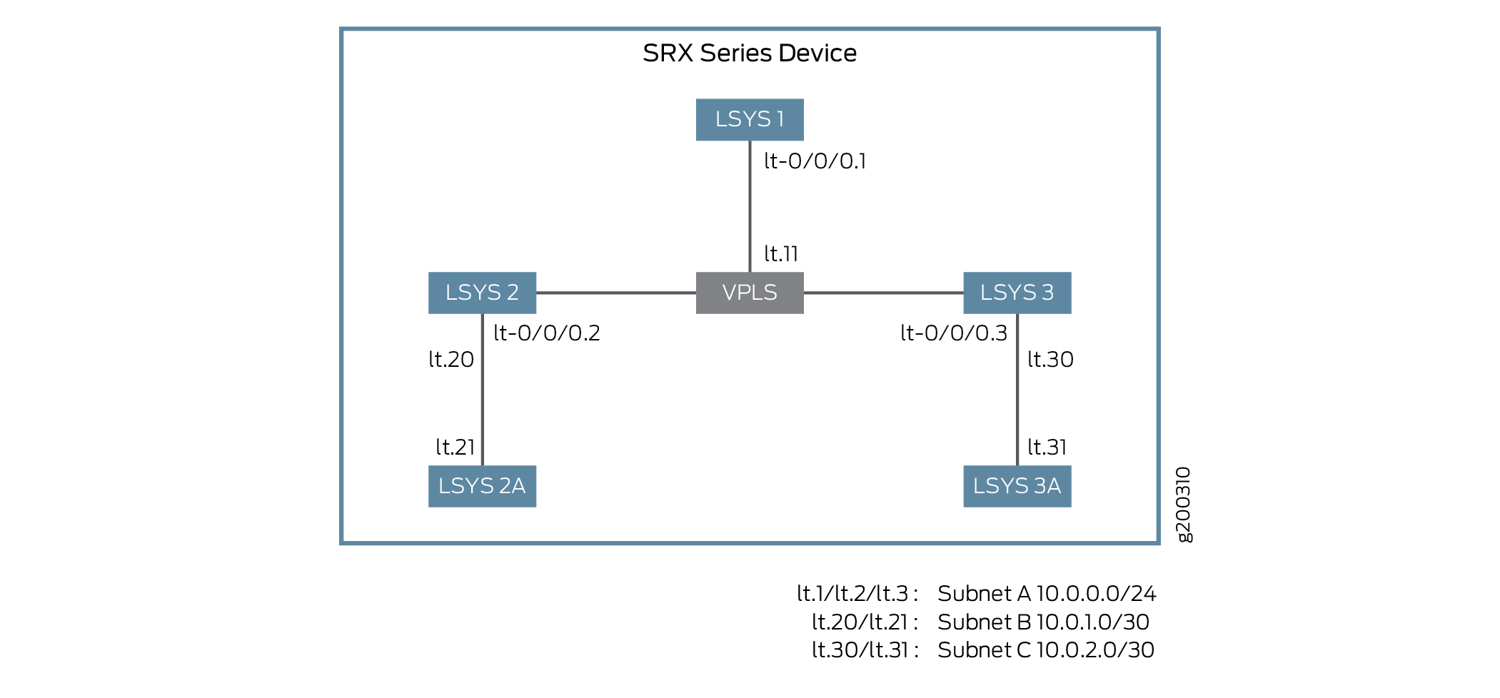
图 1 显示了逻辑系统互连的拓扑结构。
-
对于具有 LT 接口点对点连接(封装以太网)的互连逻辑系统,此示例配置逻辑隧道接口 LT-0/0/0。此示例配置安全区域并为逻辑系统分配接口。
互连逻辑系统 lt-0/0/0 接口配置以太网作为封装类型。逻辑系统中对应的对等方 lt-0/0/0 接口配置了以太网作为封装类型。安全配置文件将分配给逻辑系统。
-
对于具有 LT 接口点对点连接(封装帧中继)的逻辑互连系统,此示例配置逻辑隧道接口 LT-0/0/0。此示例配置安全区域并为逻辑系统分配接口。
互连逻辑系统 lt-0/0/0 接口配置时,帧中继作为封装类型。逻辑系统中相应的对等方 lt-0/0/0 接口配置了帧中继作为封装类型。安全配置文件将分配给逻辑系统。
-
对于具有多个 VPLS 交换机的互连逻辑系统,此示例将逻辑隧道接口 lt-0/0/0 配置为 ethernet-vpls 作为封装类型。相应的对等方 lt-0/0/0 接口和安全配置文件将分配给逻辑系统。VPLS 交换机 1 和 VPLS 交换机 2 的路由实例也会分配给逻辑系统。
图 2 显示了逻辑系统与 VPLS 交换机互连的拓扑。
图 2:使用 VPLS 交换机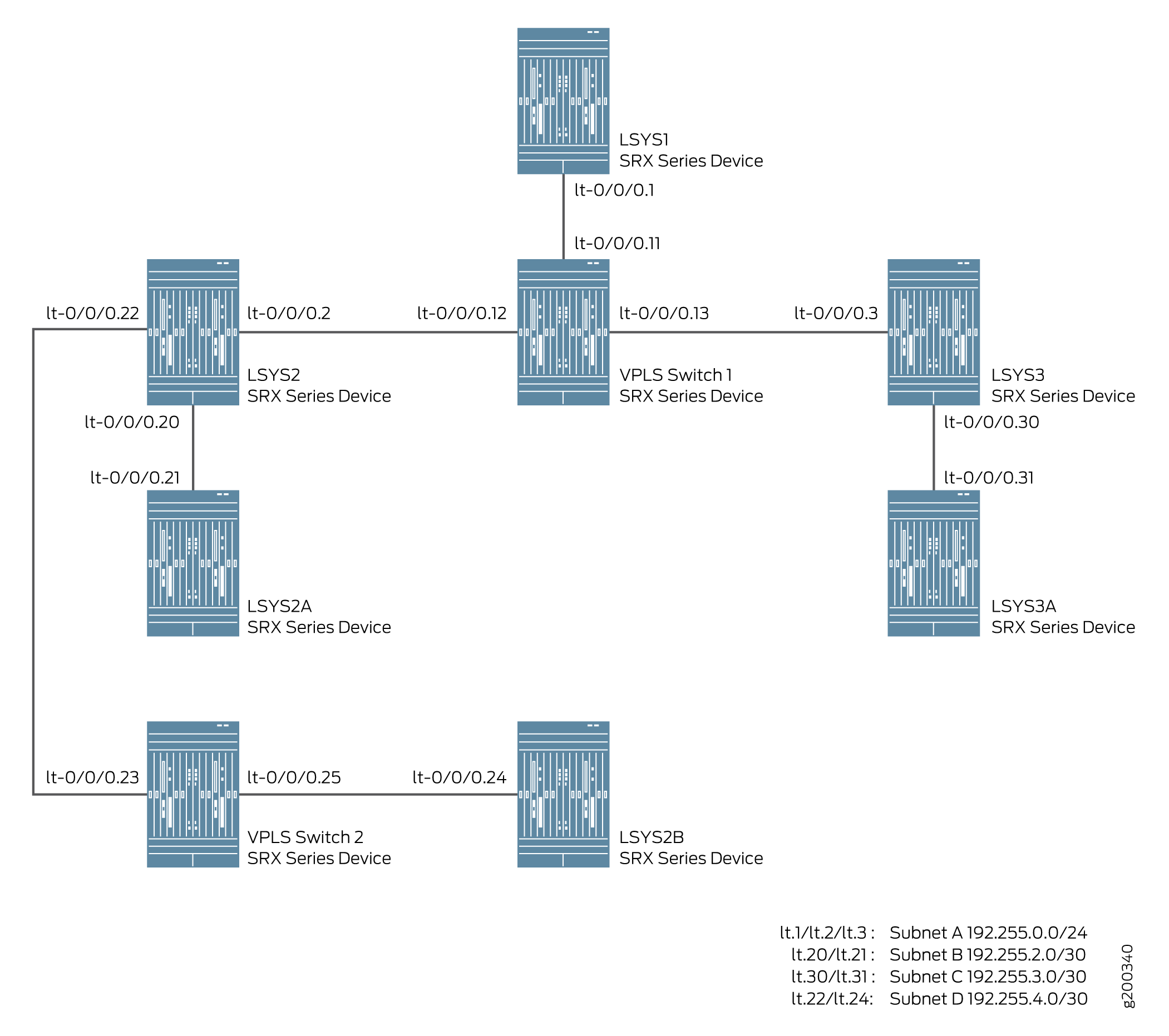 配置互连逻辑系统
注意:
配置互连逻辑系统
注意:一个逻辑系统中可以配置多个 LT 接口。
配置
要为逻辑系统配置接口,请执行以下作:
配置逻辑系统与逻辑隧道接口互连 点对点连接(封装以太网)
CLI 快速配置
要快速配置此示例,请复制以下命令,将其粘贴到文本文件中,删除所有换行符,更改详细信息,以便与网络配置匹配,将命令复制并粘贴到层次结构级别的 [edit] CLI 中,然后从配置模式进入。commit
set system security-profile SP-user logical-system LSYS2
set logical-systems LSYS2 interfaces lt-0/0/0 unit 20 encapsulation ethernet
set logical-systems LSYS2 interfaces lt-0/0/0 unit 20 peer-unit 21
set logical-systems LSYS2 interfaces lt-0/0/0 unit 20 family inet address 192.255.2.1/30
set logical-systems LSYS2 security zones security-zone LT interfaces lt-0/0/0.20
set system security-profile SP-user logical-system LSYS2A
set logical-systems LSYS2A interfaces lt-0/0/0 unit 21 encapsulation ethernet
set logical-systems LSYS2A interfaces lt-0/0/0 unit 21 peer-unit 20
set logical-systems LSYS2A interfaces lt-0/0/0 unit 21 family inet address 192.255.2.2/30
set logical-systems LSYS2A security policies from-zone LT to-zone LT policy LT match source-address any
set logical-systems LSYS2A security policies from-zone LT to-zone LT policy LT match destination-address any
set logical-systems LSYS2A security policies from-zone LT to-zone LT policy LT match application any
set logical-systems LSYS2A security policies from-zone LT to-zone LT policy LT then permit
set logical-systems LSYS2A security policies default-policy permit-all
set logical-systems LSYS2A security zones security-zone LT host-inbound-traffic system-services all
set logical-systems LSYS2A security zones security-zone LT host-inbound-traffic protocols all
set logical-systems LSYS2A security zones security-zone LT interfaces lt-0/0/0.21
分步程序
下面的示例要求您在各个配置层级中进行导航。有关作说明,请参阅《Junos OS CLI 用户指南》中的在 配置模式下使用CLI编辑器 。
-
定义安全配置文件并分配给逻辑系统。
[edit]
user@host# set system security-profile SP-user logical-system LSYS2
-
将 LT 接口设置为逻辑系统中的封装以太网。
[edit]
user@host# set logical-systems LSYS2 interfaces lt-0/0/0 unit 20 encapsulation ethernet
-
为逻辑系统 LSYS2 配置对等关系。
[edit]
user@host# set logical-systems LSYS2 interfaces lt-0/0/0 unit 20 peer-unit 21
-
指定 LT 接口的 IP 地址。
[edit]
user@host# set logical-systems LSYS2 interfaces lt-0/0/0 unit 20 family inet address 192.255.2.1/30
-
为 LT 接口设置安全区域。
[edit]
user@host# set logical-systems LSYS2 security zones security-zone LT interfaces lt-0/0/0.20
-
定义安全配置文件并分配给逻辑系统。
[edit]
user@host# set system security-profile SP-user logical-system LSYS2A
-
在逻辑系统 2A 中将 LT 接口设置为封装以太网。
[edit]
user@host# set logical-systems LSYS2A interfaces lt-0/0/0 unit 21 encapsulation ethernet
-
为逻辑系统 LSYS2A 配置对等关系。
[edit]
user@host# set logical-systems LSYS2A interfaces lt-0/0/0 unit 21 peer-unit 20
-
指定 LT 接口的 IP 地址。
[edit]
user@host# set logical-systems LSYS2A interfaces lt-0/0/0 unit 21 family inet address 192.255.2.2/30
-
配置一个安全策略,以允许从 LT 区域到 LT 策略 LT 区域的流量。
[edit]
user@host# set logical-systems LSYS2A security policies from-zone LT to-zone LT policy LT match source-address any
user@host# set logical-systems LSYS2A security policies from-zone LT to-zone LT policy LT match destination-address any
user@host# set logical-systems LSYS2A security policies from-zone LT to-zone LT policy LT match application any
user@host# set logical-systems LSYS2A security policies from-zone LT to-zone LT policy LT then permit
-
配置允许来自 default-policy 的流量的安全策略。
[edit]
user@host# set logical-systems LSYS2A security policies default-policy permit-all
-
配置安全区域。
[edit]
user@host# set logical-systems LSYS2A security zones security-zone LT host-inbound-traffic system-services all
user@host# set logical-systems LSYS2A security zones security-zone LT host-inbound-traffic protocols all
user@host# set logical-systems LSYS2A security zones security-zone LT interfaces lt-0/0/0.21
结果
-
在配置模式下,输入
show logical-systems LSYS2命令以确认您的配置。如果输出未显示预期的配置,请重复此示例中的配置说明进行更正。[edit] user@host# show logical-systems LSYS2 interfaces { lt-0/0/0 { unit 20 { encapsulation ethernet; peer-unit 21; family inet { address 192.255.2.1/30; } } unit 22 { encapsulation ethernet; peer-unit 23; family inet { address 192.255.4.1/30; } } } } security { zones { security-zone LT { interfaces { lt-0/0/0.22; lt-0/0/0.20; } } } }
-
在配置模式下,输入
show logical-systems LSYS2A命令以确认您的配置。如果输出未显示预期的配置,请重复此示例中的配置说明进行更正。[edit] user@host# show logical-systems LSYS2A interfaces { lt-0/0/0 { unit 21 { encapsulation ethernet; peer-unit 20; family inet { address 192.255.2.2/30; } } } } security { policies { from-zone LT to-zone LT { policy LT { match { source-address any; destination-address any; application any; } then { permit; } } } default-policy { permit-all; } } zones { security-zone LT { host-inbound-traffic { system-services { all; } protocols { all; } } interfaces { lt-0/0/0.21; } } } }
如果完成设备配置,请从配置模式进入。commit
配置逻辑系统与逻辑隧道接口互连 点对点连接(封装帧中继)
CLI 快速配置
要快速配置此示例,请复制以下命令,将其粘贴到文本文件中,删除所有换行符,更改详细信息,以便与网络配置匹配,将命令复制并粘贴到层次结构级别的 [edit] CLI 中,然后从配置模式进入。commit
set system security-profile SP-user logical-system LSYS3A
set logical-systems LSYS3 interfaces lt-0/0/0 unit 30 encapsulation frame-relay
set logical-systems LSYS3 interfaces lt-0/0/0 unit 30 dlci 16
set logical-systems LSYS3 interfaces lt-0/0/0 unit 30 peer-unit 31
set logical-systems LSYS3 interfaces lt-0/0/0 unit 30 family inet address 192.255.3.1/30
set logical-systems LSYS3 security zones security-zone LT interfaces lt-0/0/0.30
set logical-systems LSYS3A interfaces lt-0/0/0 unit 31 encapsulation frame-relay
set logical-systems LSYS3A interfaces lt-0/0/0 unit 31 dlci 16
set logical-systems LSYS3A interfaces lt-0/0/0 unit 31 peer-unit 30
set logical-systems LSYS3A interfaces lt-0/0/0 unit 31 family inet address 192.255.3.2/30
set logical-systems LSYS3A security policies from-zone LT to-zone LT policy LT match source-address any
set logical-systems LSYS3A security policies from-zone LT to-zone LT policy LT match destination-address any
set logical-systems LSYS3A security policies from-zone LT to-zone LT policy LT match application any
set logical-systems LSYS3A security policies from-zone LT to-zone LT policy LT then permit
set logical-systems LSYS3A security policies default-policy permit-all
set logical-systems LSYS3A security zones security-zone LT host-inbound-traffic system-services all
set logical-systems LSYS3A security zones security-zone LT host-inbound-traffic protocols all
set logical-systems LSYS3A security zones security-zone LT interfaces lt-0/0/0.31
分步程序
下面的示例要求您在各个配置层级中进行导航。有关作说明,请参阅在 配置模式下使用 CLI 编辑器。
-
定义安全配置文件并分配给逻辑系统。
[edit]
user@host# set system security-profile SP-user logical-system LSYS3A
-
在逻辑系统中将 LT 接口设置为封装帧中继。
[edit]
user@host# set logical-systems LSYS3 interfaces lt-0/0/0 unit 30 encapsulation frame-relay
-
通过包含 dlci 来配置逻辑隧道接口。
[edit]
user@host# set logical-systems LSYS3 interfaces lt-0/0/0 unit 30 dlci 16
-
在 LT 接口之间配置对等单元关系,从而创建点对点连接。
[edit]
user@host# set logical-systems LSYS3 interfaces lt-0/0/0 unit 30 peer-unit 31
-
指定 LT 接口的 IP 地址。
[edit]
user@host# set logical-systems LSYS3 interfaces lt-0/0/0 unit 30 family inet address 192.255.3.1/30
-
为 LT 接口设置安全区域。
[edit]
user@host# set logical-systems LSYS3 security zones security-zone LT interfaces lt-0/0/0.30
-
在逻辑系统中将 LT 接口设置为封装帧中继。
[edit]
user@host# set logical-systems LSYS3A interfaces lt-0/0/0 unit 31 encapsulation frame-relay
-
通过包含 dlci 来配置逻辑隧道接口。
[edit]
user@host# set logical-systems LSYS3A interfaces lt-0/0/0 unit 31 dlci 16
-
在 LT 接口之间配置对等单元关系,从而创建点对点连接。
[edit]
user@host# set logical-systems LSYS3A interfaces lt-0/0/0 unit 31 peer-unit 30
-
指定 LT 接口的 IP 地址。
[edit]
user@host# set logical-systems LSYS3A interfaces lt-0/0/0 unit 31 family inet address 192.255.3.2/30
-
配置一个安全策略,以允许从 LT 区域到 LT 策略 LT 区域的流量。
[edit]
user@host# set logical-systems LSYS3A security policies from-zone LT to-zone LT policy LT match source-address any
user@host# set logical-systems LSYS3A security policies from-zone LT to-zone LT policy LT match destination-address any
user@host# set logical-systems LSYS3A security policies from-zone LT to-zone LT policy LT match application any
user@host# set logical-systems LSYS3A security policies from-zone LT to-zone LT policy LT then permit
-
配置允许来自 default-policy 的流量的安全策略。
[edit]
user@host# set logical-systems LSYS3A security policies default-policy permit-all
-
配置安全区域。
[edit]
user@host# set logical-systems LSYS3A security zones security-zone LT host-inbound-traffic system-services all
user@host# set logical-systems LSYS3A security zones security-zone LT host-inbound-traffic protocols all
user@host# set logical-systems LSYS3A security zones security-zone LT interfaces lt-0/0/0.31
结果
-
在配置模式下,输入
show logical-systems LSYS3命令以确认您的配置。如果输出未显示预期的配置,请重复此示例中的配置说明进行更正。[edit] user@host# show logical-systems LSYS3 interfaces { lt-0/0/0 { unit 30 { encapsulation frame-relay; dlci 16; peer-unit 31; family inet { address 192.255.3.1/30; } } } } security { zones { security-zone LT { interfaces { lt-0/0/0.30; } } } }
-
在配置模式下,输入
show logical-systems LSYS3A命令以确认您的配置。如果输出未显示预期的配置,请重复此示例中的配置说明进行更正。[edit] user@host# show logical-systems LSYS3A
    interfaces {
        lt-0/0/0 {
            unit 31 {
                encapsulation frame-relay;
                dlci 16;
                peer-unit 30;
                family inet {
                    address 192.255.3.2/30;
                }
            }
        }
    }
    security {
        policies {
            from-zone LT to-zone LT {
                policy LT {
                    match {
                        source-address any;
                        destination-address any;
                        application any;
                    }
                    then {
                        permit;
                    }
                }
            }
            default-policy {
                permit-all;
            }
        }
        zones {
            security-zone LT {
                host-inbound-traffic {
                    system-services {
                        all;
                    }
                    protocols {
                        all;
                    }
                }
                interfaces {
                    lt-0/0/0.31;
                }
            }
        }
    }
如果完成设备配置,请从配置模式进入。commit
配置逻辑系统与多个 VPLS 交换机互连
CLI 快速配置
要快速配置此示例,请复制以下命令,将其粘贴到文本文件中,删除所有换行符,更改详细信息,以便与网络配置匹配,将命令复制并粘贴到层次结构级别的 [edit] CLI 中,然后从配置模式进入。commit
set interfaces lt-0/0/0 unit 11 encapsulation ethernet-vpls
set interfaces lt-0/0/0 unit 11 peer-unit 1
set interfaces lt-0/0/0 unit 12 encapsulation ethernet-vpls
set interfaces lt-0/0/0 unit 12 peer-unit 2
set interfaces lt-0/0/0 unit 13 encapsulation ethernet-vpls
set interfaces lt-0/0/0 unit 13 peer-unit 3
set interfaces lt-0/0/0 unit 23 encapsulation ethernet-vpls
set interfaces lt-0/0/0 unit 23 peer-unit 22
set interfaces lt-0/0/0 unit 25 encapsulation ethernet-vpls
set interfaces lt-0/0/0 unit 25 peer-unit 24
set routing-instances vpls-switch-1 instance-type vpls
set routing-instances vpls-switch-1 interface lt-0/0/0.11
set routing-instances vpls-switch-1 interface lt-0/0/0.12
set routing-instances vpls-switch-1 interface lt-0/0/0.13
set routing-instances vpls-switch-2 instance-type vpls
set routing-instances vpls-switch-2 interface lt-0/0/0.23
set routing-instances vpls-switch-2 interface lt-0/0/0.25
set logical-systems LSYS1 interfaces lt-0/0/0 unit 1 encapsulation ethernet
set logical-systems LSYS1 interfaces lt-0/0/0 unit 1 peer-unit 11
set logical-systems LSYS1 interfaces lt-0/0/0 unit 1 family inet address 192.255.0.1/24
set logical-systems LSYS2 interfaces lt-0/0/0 unit 2 encapsulation ethernet
set logical-systems LSYS2 interfaces lt-0/0/0 unit 2 peer-unit 12
set logical-systems LSYS2 interfaces lt-0/0/0 unit 2 family inet address 192.255.0.2/24
set logical-systems LSYS2 interfaces lt-0/0/0 unit 22 encapsulation ethernet
set logical-systems LSYS2 interfaces lt-0/0/0 unit 22 peer-unit 23
set logical-systems LSYS2 interfaces lt-0/0/0 unit 22 family inet address 192.255.4.1/30
set logical-systems LSYS3 interfaces lt-0/0/0 unit 3 encapsulation ethernet
set logical-systems LSYS3 interfaces lt-0/0/0 unit 3 peer-unit 13
set logical-systems LSYS3 interfaces lt-0/0/0 unit 3 family inet address 192.255.0.3/24
set logical-systems LSYS2B interfaces lt-0/0/0 unit 24 encapsulation ethernet
set logical-systems LSYS2B interfaces lt-0/0/0 unit 24 peer-unit 25
set logical-systems LSYS2B interfaces lt-0/0/0 unit 24 family inet address 192.255.4.2/30
set system security-profile SP-user policy maximum 100
set system security-profile SP-user policy reserved 50
set system security-profile SP-user zone maximum 60
set system security-profile SP-user zone reserved 10
set system security-profile SP-user flow-session maximum 100
set system security-profile SP-user flow-session reserved 50
set system security-profile SP-user logical-system LSYS1
set system security-profile SP-user logical-system LSYS2
set system security-profile SP-user logical-system LSYS3
set system security-profile SP-user logical-system LSYS2B
分步程序
下面的示例要求您在各个配置层级中进行导航。有关作说明,请参阅在 配置模式下使用 CLI 编辑器。
-
配置 lt-0/0/0 接口。
[edit]
user@host# set interfaces lt-0/0/0 unit 11 encapsulation ethernet-vpls
user@host# set interfaces lt-0/0/0 unit 11 peer-unit 1
user@host# set interfaces lt-0/0/0 unit 12 encapsulation ethernet-vpls
user@host# set interfaces lt-0/0/0 unit 12 peer-unit 2
user@host# set interfaces lt-0/0/0 unit 13 encapsulation ethernet-vpls
user@host# set interfaces lt-0/0/0 unit 13 peer-unit 3
user@host# set interfaces lt-0/0/0 unit 23 encapsulation ethernet-vpls
user@host# set interfaces lt-0/0/0 unit 23 peer-unit 22
user@host# set interfaces lt-0/0/0 unit 25 encapsulation ethernet-vpls
user@host# set interfaces lt-0/0/0 unit 25 peer-unit 24
-
为 VPLS 交换机配置路由实例,并为其添加接口。
[edit]
user@host# set routing-instances vpls-switch-1 instance-type vpls
user@host# set routing-instances vpls-switch-1 interface lt-0/0/0.11
user@host# set routing-instances vpls-switch-1 interface lt-0/0/0.12
user@host# set routing-instances vpls-switch-1 interface lt-0/0/0.13
user@host# set routing-instances vpls-switch-2 instance-type vpls
user@host# set routing-instances vpls-switch-2 interface lt-0/0/0.23
user@host# set routing-instances vpls-switch-2 interface lt-0/0/0.25
-
使用 lt-0/0/0.1 接口和对等方 lt-0/0/0.11 配置 LSYS1。
[edit]
user@host# set logical-systems LSYS1 interfaces lt-0/0/0 unit 1 encapsulation ethernet
user@host# set logical-systems LSYS1 interfaces lt-0/0/0 unit 1 peer-unit 11
user@host# set logical-systems LSYS1 interfaces lt-0/0/0 unit 1 family inet address 192.255.0.1/24
-
使用 lt-0/0/0.2 接口和对等方 lt-0/0/0.12 配置 LSYS2。
[edit]
user@host# set logical-systems LSYS2 interfaces lt-0/0/0 unit 2 encapsulation ethernet
user@host# set logical-systems LSYS2 interfaces lt-0/0/0 unit 2 peer-unit 12
user@host# set logical-systems LSYS2 interfaces lt-0/0/0 unit 2 family inet address 192.255.0.2/24
user@host# set logical-systems LSYS2 interfaces lt-0/0/0 unit 22 encapsulation ethernet
user@host# set logical-systems LSYS2 interfaces lt-0/0/0 unit 22 peer-unit 23
user@host# set logical-systems LSYS2 interfaces lt-0/0/0 unit 22 family inet address 192.255.4.1/30
-
使用 lt-0/0/0.3 接口和对等方 lt-0/0/0.13 配置 LSYS3
[edit]
user@host# set logical-systems LSYS3 interfaces lt-0/0/0 unit 3 encapsulation ethernet
user@host# set logical-systems LSYS3 interfaces lt-0/0/0 unit 3 peer-unit 13
user@host# set logical-systems LSYS3 interfaces lt-0/0/0 unit 3 family inet address 192.255.0.3/24
-
使用 lt-0/0/0 接口和对等单元 24 配置 LSYS2B。
[edit]
user@host# set logical-systems LSYS2B interfaces lt-0/0/0 unit 24 encapsulation ethernet
user@host# set logical-systems LSYS2B interfaces lt-0/0/0 unit 24 peer-unit 25
user@host# set logical-systems LSYS2B interfaces lt-0/0/0 unit 24 family inet address 192.255.4.2/30
-
为逻辑系统分配安全配置文件。
[edit]
user@host# set system security-profile SP-user policy maximum 100
user@host# set system security-profile SP-user policy reserved 50
user@host# set system security-profile SP-user zone maximum 60
user@host# set system security-profile SP-user zone reserved 10
user@host# set system security-profile SP-user flow-session maximum 100
user@host#set system security-profile SP-user flow-session reserved 50
user@host# set system security-profile SP-user logical-system LSYS1
user@host# set system security-profile SP-user logical-system LSYS2
user@host# set system security-profile SP-user logical-system LSYS3
user@host# set system security-profile SP-user logical-system LSYS2B
结果
-
在配置模式下,输入
show interfaces lt-0/0/0,命令以确认您的配置。如果输出未显示预期的配置,请重复此示例中的配置说明进行更正[edit] user@host# show interfaces lt-0/0/0 unit 11 { encapsulation ethernet-vpls; peer-unit 1; } unit 12 { encapsulation ethernet-vpls; peer-unit 2; } unit 13 { encapsulation ethernet-vpls; peer-unit 3; } unit 23 { encapsulation ethernet-vpls; peer-unit 22; } unit 25 { encapsulation ethernet-vpls; peer-unit 24; } -
在配置模式下,输入
show routing-instances,命令以确认您的配置。如果输出未显示预期的配置,请重复此示例中的配置说明进行更正。[edit] user@host# show routing-instances vpls-switch-1 { instance-type vpls; interface lt-0/0/0.11; interface lt-0/0/0.12; interface lt-0/0/0.13; } vpls-switch-2 { instance-type vpls; interface lt-0/0/0.23; interface lt-0/0/0.25; } -
在配置模式下,输入
show logical-systems LSYS1,命令以确认您的配置。如果输出未显示预期的配置,请重复此示例中的配置说明进行更正。[edit] user@host# show logical-systems LSYS1 interfaces { lt-0/0/0 { unit 1 { encapsulation ethernet; peer-unit 11; family inet { address 192.255.0.1/24; } } } } -
在配置模式下,输入
show logical-systems LSYS2,命令以确认您的配置。如果输出未显示预期的配置,请重复此示例中的配置说明进行更正。[edit] user@host# show logical-systems LSYS2 interfaces { lt-0/0/0 { unit 2 { encapsulation ethernet; peer-unit 12; family inet { address 192.255.0.2/24; } } unit 22 { encapsulation ethernet; peer-unit 23; family inet { address 192.255.4.1/30; } } } } -
在配置模式下,输入
show logical-systems LSYS3,命令以确认您的配置。如果输出未显示预期的配置,请重复此示例中的配置说明进行更正。[edit] user@host# show logical-systems LSYS3 interfaces { lt-0/0/0 { unit 3 { encapsulation ethernet; peer-unit 13; family inet { address 192.255.0.3/24; } } } } -
在配置模式下,输入
show logical-systems LSYS2B,命令以确认您的配置。如果输出未显示预期的配置,请重复此示例中的配置说明进行更正。[edit] user@host# show logical-systems LSYS2B interfaces { lt-0/0/0 { unit 24 { encapsulation ethernet; peer-unit 25; family inet { address 192.255.4.2/30; } } } } -
在配置模式下,输入
show system security-profile,命令以确认您的配置。如果输出未显示预期的配置,请重复此示例中的配置说明进行更正。[edit] user@host# show system security-profile SP-user { policy { maximum 100; reserved 50; } zone { maximum 60; reserved 10; } flow-session { maximum 100; reserved 50; } logical-system [ LSYS1 LSYS2 LSYS3 LSYS2B ]; }
如果完成设备配置,请从配置模式进入。commit
验证
要确认配置工作正常,请执行以下任务:
验证所有逻辑系统的安全性配置文件
目的
验证每个逻辑系统的安全配置文件。
行动
在作模式下,输入命令 show system security-profile security-log-stream-number logical-system all 。
user@host> show system security-profile security-log-stream-number logical-system all
logical system name   security profile name       usage    reserved   maximum
root-logical-system   Default-Profile                 2           0          2000
LSYS1                 SP-user                         1          10          60
LSYS2                 SP-user                         1          10          60
LSYS2B                SP-user                         1          10          60
LSYS3                 SP-user                         1          10          60
意义
配置 security-log-stream 时,输出提供逻辑系统的使用情况和保留值。
验证所有逻辑系统的 LT 接口
目的
验证逻辑系统的接口。
行动
在作模式下,输入命令 show interfaces lt-0/0/0 terse 。
user@host> show interfaces lt-0/0/0 terse
Interface               Admin Link Proto    Local                 Remote
lt-0/0/0                up    up
lt-0/0/0.1              up    up   inet     192.255.0.1/24
lt-0/0/0.2              up    up   inet     192.255.0.2/24
lt-0/0/0.3              up    up   inet     192.255.0.3/24
lt-0/0/0.11             up    up   vpls
lt-0/0/0.12             up    up   vpls
lt-0/0/0.13             up    up   vpls
lt-0/0/0.22             up    up   inet     192.255.4.1/30
lt-0/0/0.23             up    up   vpls
lt-0/0/0.24             up    up   inet     192.255.4.2/30
lt-0/0/0.25             up    up   vpls
lt-0/0/0.32767          up    up
意义
输出提供 LT 接口的状态。所有 LT 接口均已开启。