ON THIS PAGE
Configure the Underlay (with EBGP) And the Overlay (with IBGP)
Configure the Tenant VRF Instances for IGMPv2 and IGMPv3 Multicast Receivers
Configure Server Leaf to TOR Interfaces and Ethernet Segment Identifiers (ESIs) for EVPN Multihoming
Configure AR Replicator Role on OISM Spine Devices and AR Leaf Role on OISM Leaf Devices
Optimized Intersubnet Multicast (OISM) with Assisted Replication (AR) for Edge-Routed Bridging Overlays
This example shows how to configure our original optimized intersubnet multicast (OISM) implementation with assisted replication (AR) in a large EVPN-VXLAN edge-routed bridging (ERB) overlay fabric.
In EVPN ERB overlay fabric designs, the leaf devices route traffic between tenant VLANs as well as forwarding traffic within tenant VLANs. To support efficient multicast traffic flow in a scaled ERB overlay fabric with both internal and external multicast sources and receivers, we provide a multicast configuration model based on RFC9625—EVPN Optimized Inter-Subnet Multicast (OISM) Forwarding . OISM combines the best aspects of ERB and CRB overlay designs for multicast traffic together to provide the most efficient multicast traffic flow in ERB overlay fabrics, especially in scaled environments.
OISM enables ERB overlay fabrics to:
-
Support multicast traffic with sources and receiver both inside and outside the fabric.
-
Minimize multicast control and data traffic flow in the EVPN core to optimize performance in scaled environments.
Our original OISM implementation, called regular OISM, uses a symmetric bridge domains model. With this model, you configure all tenant VLANs in the fabric symmetrically on all OISM devices. This example shows a regular OISM configuration.
On some platforms we also support an enhanced version of OISM that uses an asymmetric bridge domains model in which you don't need to configure all tenant VLANs symmetrically on all OISM devices. The OISM configuration elements and steps are almost the same for regular and enhanced OISM. The main difference, besides setting either OISM mode, is how you configure the tenant VLANs with each mode. Enhanced OISM also has some important operational differences to support the asymmetric bridge domains model. See Enhanced Optimized Intersubnet Multicast (OISM) Implementation for an enhanced OISM configuration.
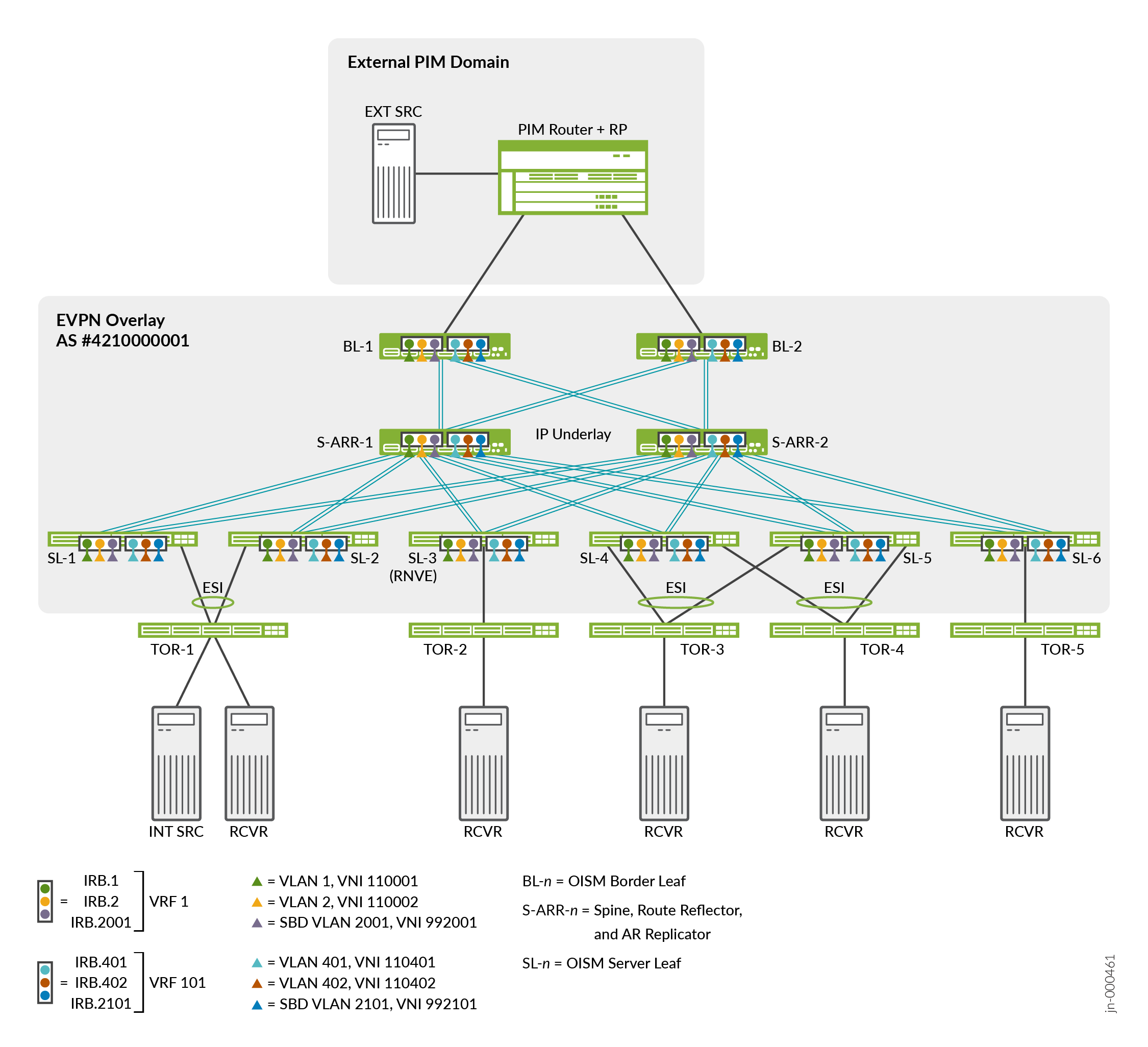
Figure 1 shows the ERB overlay reference architecture in which we validated OISM and AR on supported devices in this example.
Starting in Junos OS Release 24.4R1, we have tested regular OISM at scale in environments that also include configurations for the following features:
-
BGP unnumbered peering with an IPv6 underlay (also referred to as BGP auto-discovery or BGP auto-peering).
See BGP Unnumbered IPv6 Underlay in an EVPN-VXLAN Data Center.
-
Non-revertive preference-based designated forwarder (DF) election.
We qualified those features with OISM but without AR enabled. We don't include configuration instructions for those features in the regular OISM use cases described here.
Here is a summary of OISM components, configuration elements, and operation in this environment. For full details on how OISM works in different scenarios and available OISM support on different platforms, see Optimized Intersubnet Multicast in EVPN Networks.
-
In this example, the OISM devices take one of these device roles:
-
Server leaf (SL)—Leaf devices that link to the access side (internal) top-of-rack (TOR) devices that host the multicast servers and receivers inside the fabric. The SL devices can act as AR leaf devices.
-
Border Leaf (BL)—Leaf devices that link to an external PIM domain to manage multicast flow to and from external multicast sources and receivers. The BL devices can also act as AR leaf devices.
-
AR Replicator Spine (S-ARR)—IP fabric transit devices that serve as route reflectors in the ERB overlay fabric and also as the AR replicator devices working with OISM. When the spine devices in an ERB overlay act as AR replicators, they must run EVPN-VXLAN and no longer function simply as lean spines.
-
-
In this example, you configure OISM with a MAC-VRF EVPN instance with the VLAN-aware service type (supports multiple VLANs in the MAC-VRF instance) on all SL, BL, and S-ARR devices. You don’t need to configure an EVPN instance on the external PIM router.
-
This example configures regular OISM, which uses a symmetric bridge domains model. With this model, you configure all tenant VLANs (also called revenue bridge domains or revenue VLANs) and virtual routing and forwarding (VRF) instances in the fabric on all OISM leaf devices. If you configure OISM with AR, you also configure these elements on the spine devices that act as AR replicators.
-
OISM leaf devices do intrasubnet bridging, and use a local routing model for intersubnet (Layer 3 [L3]) multicast traffic to conserve bandwidth and avoid hairpinning in the EVPN core. See Local Routing on OISM Devices for details.
-
SL devices forward multicast source traffic into the EVPN core only on the source VLAN.
-
BL devices forward traffic from external multicast sources into the EVPN core toward internal receivers only on a supplemental bridge domain called the SBD. The SBD design enables the local routing model and solves other issues with externally sourced traffic. For each tenant VRF instance, you assign a VLAN and a corresponding IRB interface for the SBD.
-
OISM SL devices receive multicast traffic from internal sources on the source VLAN, or from external sources through the BL devices on the SBD. For internally sourced traffic, the SL devices locally bridge the traffic to receivers on the source VLAN, and use IRB interfaces to locally route the traffic to receivers on other VLANs. Upon receiving traffic from outside the fabric, the SL devices use IRB interfaces to locally route the traffic from the SBD to the tenant VLANs and then to their locally attached receivers.
-
-
We support OISM with IGMPv2 (any-source multicast [ASM] reports only) or IGMPv3 (source-specific multicast [SSM] reports only). OISM requires that you enable IGMP snooping with either IGMP version. We use Protocol Independent Multicast (PIM) in sparse mode for multicast routing with different options on SL and BL devices according to their functions.
Note:To support both IGMPv2 and IGMPv3 receivers on the same device, you must:
-
Use different tenant VRF instances to support the receivers for each IGMP version.
-
Configure different VLANs and corresponding IRB interfaces that support the receivers for each IGMP version.
-
Associate the IRB interfaces for each version with the corresponding tenant VRF instance.
See Considerations for OISM Configurations for details on the required configuration considerations. The configuration we tested here accommodates receivers for both versions on the same device.
-
-
With IGMP snooping, OISM also optimizes multicast traffic using EVPN Type 6 routes for selective multicast Ethernet tag (SMET) forwarding. With SMET, OISM devices only forward traffic for a multicast group to other devices in the fabric with receivers that show interest in receiving that traffic. (Multicast receivers send IGMP join messages to request traffic for a multicast group.)
In the regular OISM model used here, OISM devices advertise EVPN Type 6 routes only on the SBD.
-
OISM supports EVPN multihoming with multicast traffic. The fabric can include receivers behind TOR devices that are multihomed in an Ethernet segment (ES) to more than one OISM leaf device. You configure an ES identifier (ESI) for the links in the ES.
OISM devices use EVPN Type 7 (Join Sync) and Type 8 (Leave Sync) routes to synchronize the multicast state among the multihoming peer devices that serve an ES.
In this environment, we validate OISM and AR together at scale with the AR replicator role on the spine devices. Configure AR Replicator Role on OISM Spine Devices and AR Leaf Role on OISM Leaf Devices explains more about how AR works in this example. When the AR replicator role is not collocated with an OISM border leaf role on the same device, as in this example, we say the AR replicator operates in standalone AR replicator mode. The OISM SL and BL devices act as AR leaf devices.
We call devices that don’t support AR regular network virtualization edge (RNVE) devices. The test environment includes an SL device (see SL-3 in Figure 1) on which we don’t configure the AR leaf role to simulate an RNVE device. With RNVE devices in the fabric:
-
The RNVE devices use ingress replication to forward multicast traffic to other leaf devices in the fabric.
-
The AR replicators use ingress replication instead of AR to forward multicast source data to the RNVE devices.
In this chapter, we show configuration and verification for a small subset of the scaled environment in which we validate OISM and AR together. Although the scaled test environment includes more devices, configured elements, multicast sources, and subscribed receivers, in this example we show configuration and verification output for the following elements:
-
One EVPN instance, MACVRF-1, which is a MAC-VRF instance with VLAN-aware service type and VXLAN encapsulation.
-
Multicast stream use cases that encompass:
-
IGMPv2 or IGMPv3 traffic.
-
Internal or external multicast sources.
-
-
Two tenant VRF instances, one for IGMPv3 receivers and one for IGMPv2 receivers.
For each tenant VRF instance, we define:
-
Four tenant VLANs with VXLAN tunnel network identifier (VNI) mappings, and corresponding IRB interfaces in the tenant VRF instance.
In the OISM design, we refer to the tenant VLANs as revenue bridge domains or revenue VLANs.
-
One SBD VLAN mapped to a VNI, and a corresponding IRB interface in the tenant VRF instance.
-
-
One multicast source inside the data center, and one multicast source outside the data center in the external PIM domain.
You configure the BL devices to act as PIM EVPN gateway (PEG) devices for the EVPN fabric. In this example, we connect PEG devices through classic L3 interfaces to an external PIM router and PIM rendezvous point (RP). The L3 interfaces on each of the BL PEG devices link to the external PIM router on different subnets.
-
Multicast receivers that subscribe to one or more multicast groups.
Note:Each multicast stream has multiple receivers subscribed to traffic from each source. The multicast traffic verification commands in this example focus on the first receiver device in the Receivers column in Table 1.
See Table 1 for a summary of these elements and their values. Figure 1 illustrates the device roles and the first two corresponding IRB interfaces, VLANs, and VNI mappings for each of the tenant VRFs in the table.
|
Multicast Stream |
Tenant VRF |
VLANs, IRB Interfaces, and VNI Mappings |
Source |
Receivers |
Multicast Groups |
|
|---|---|---|---|---|---|---|
|
Internal source, internal receivers with IGMPv3—SSM reports only |
VRF-1 |
VLAN-1, irb.1 |
VNI 110001 |
TOR-1 on VLAN-1 (Multihomed to SL-1 and SL-2) |
TOR-4 (Multihomed to SL-4 and SL-5) Other receivers: TOR-2 (Single-homed to SL-3) TOR-3 (Multihomed to SL-4 and SL-5) TOR-5 (Single-homed to SL-6) |
233.252.0.21 through 233.252.0.23 233.252.0.121 through 233.252.0.123 |
|
VLAN-2, irb.2 |
VNI 110002 |
|||||
|
VLAN-3, irb.3 |
VNI 110003 |
|||||
|
VLAN-4, irb.4 |
VNI 110004 |
|||||
|
(SBD) VLAN-2001, irb.2001 |
VNI 992001 |
|||||
|
External source, internal receivers with IGMPv2—ASM reports only |
VRF-101 |
VLAN-401, irb.401 |
VNI 110401 |
External Source (In External PIM Domain) |
TOR-1 on VLAN-1 (Multihomed to SL-1 and SL2) Other receivers: TOR-2 (Single-homed to SL-3) TOR-3 (Multihomed to SL-4 and SL-5) TOR-4 (Multihomed to SL-4 and SL-5) TOR-5 (Single-homed to SL-6) |
233.252.0.1 through 233.252.0.3 233.252.0.101 through 233.252.0.103 |
|
VLAN-402, irb.402 |
VNI 110402 |
|||||
|
VLAN-403, irb.403 |
VNI 110403 |
|||||
|
VLAN-404, irb.404 |
VNI 110404 |
|||||
|
(SBD) VLAN-2101, irb.2101 |
VNI 992101 |
|||||
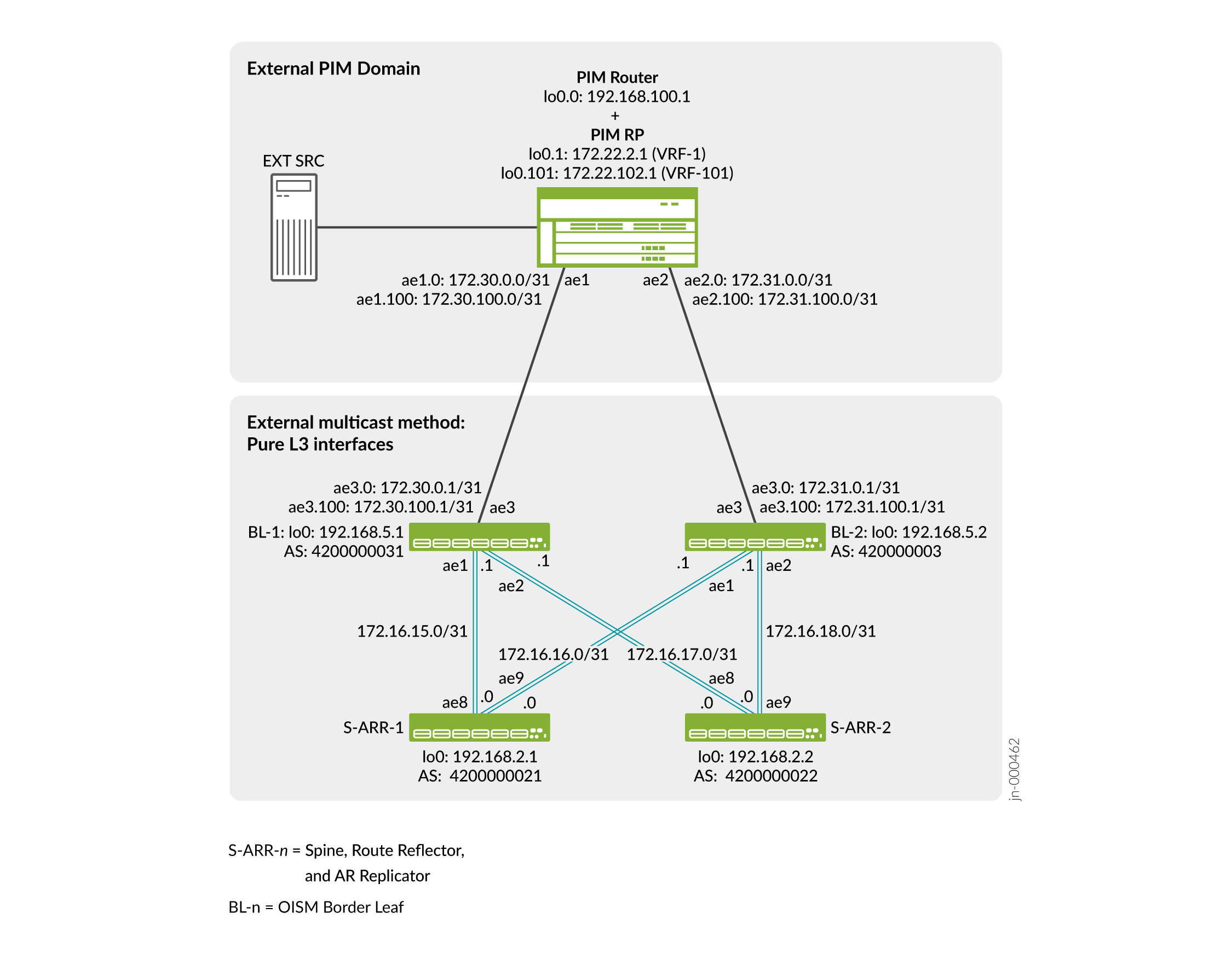
See Table 2 for a summary of the BL device and external PIM router L3 connection parameters. In this example, the BL devices both use aggregated Ethernet (AE) interface ae3 for the external L3 connection, with different subnets per BL device. In the scaled-out test environment, the configuration uses a range of logical units on the ae3 interface with corresponding VLANs per tenant VRF, starting with unit 0 and VLAN-3001 for VRF-1. We focus on tenant VRF instances VRF-1 and VRF-101 in this example.
|
BL Device |
Tenant VRF Instance |
External L3 Interface Logical Unit |
Associated VLAN |
BL L3 Logical Interface IP Address |
PIM Router Logical Interface and IP Address |
PIM RP Logical Unit and IP Address |
|---|---|---|---|---|---|---|
|
BL-1 |
VRF-1 |
unit 0: ae3.0 |
VLAN-3001 |
172.30.0.1 |
ae1.0: 172.30.0.0 |
lo0.1: 172.22.2.1 |
|
VRF-101 |
unit 100: ae3.100 |
VLAN-3101 |
172.30.100.1 |
ae1.100: 172.30.100.0 |
lo0.101: 172.22.102.1 |
|
|
BL-2 |
VRF-1 |
unit 0: ae3.0 |
VLAN-3001 |
172.31.0.1 |
ae2.0: 172.31.0.0 |
lo0.1: 172.22.2.1 |
|
VRF-101 |
unit 100: ae3.100 |
VLAN-3101 |
172.31.100.1 |
ae2.100: 172.31.100.0 |
lo0.101: 172.22.102.1 |
You configure these parameters in Configure the Border Leaf Devices for External Multicast Connectivity, PIM EVPN Gateway Role, and PIM Options.
We divide the configuration into several sections.
Configure the Underlay (with EBGP) And the Overlay (with IBGP)
We use eBGP for the underlay and iBGP for the overlay following the reference architectures in IP Fabric Underlay Network Design and Implementation and Configure IBGP for the Overlay.
This example uses AE interfaces with one or two member links each for all of the connections for redundancy.
Figure 2 shows the AE interface IP addresses for the links between the S-ARR devices and the BL devices.
Note:You configure the L3 interfaces from the BL devices to the external PIM router in Configure the Border Leaf Devices for External Multicast Connectivity, PIM EVPN Gateway Role, and PIM Options
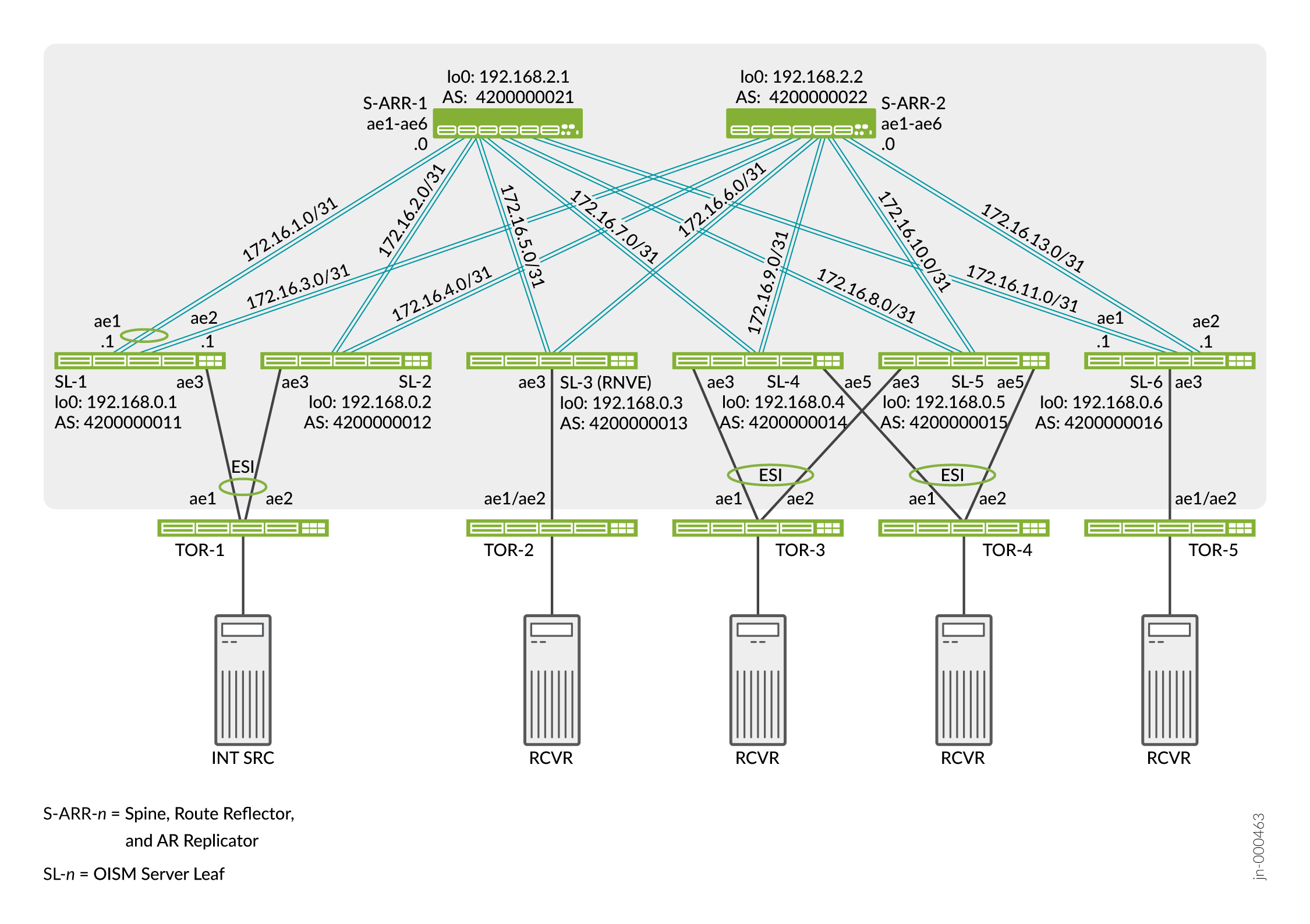
Figure 3 shows the AE interface IP addresses for the links between the S-ARR devices and the SL devices.
Note:You configure the links from the SL devices to the TOR devices in Configure Server Leaf to TOR Interfaces and Ethernet Segment Identifiers (ESIs) for EVPN Multihoming
Configure an OISM-Enabled EVPN MAC-VRF Instance
The scaled test environment includes multiple MAC-VRF EVPN instances. We show one instance called MACVRF-1 here that we use for OISM and AR traffic.
We require that you enable the shared tunnels feature
on the QFX5000 line of switches running Junos OS with a MAC-VRF instance
configuration. This feature prevents problems with VTEP scaling on
the device when the configuration uses multiple MAC-VRF instances.
When you configure shared tunnels, the device minimizes the number
of next-hop entries to reach remote VTEPs. You globally enable shared
VXLAN tunnels on the device using the shared-tunnels statement
at the [edit forwarding-options evpn-vxlan] hierarchy level.
You must reboot the device for this setting to take effect.
This statement is optional on the QFX10000 line of switches running Junos OS, which can handle higher VTEP scaling than the QFX5000 line of switches. On devices running Junos OS Evolved in EVPN-VXLAN fabrics, shared tunnels are enabled by default.
Configure the elements in these steps on all SL, BL, and S-ARR devices.
This example includes the AR multicast optimization with OISM. The spine devices (S-ARR-1 and S-ARR-2) in the fabric serve as standalone AR replicator devices. For AR to work with the regular OISM symmetric bridge domains model, you must also configure all the common OISM SL and BL elements on the standalone AR replicator devices, such as the MAC-VRF instance, VLANs, tenant VRFs, and IRB interfaces.
If the spine devices don’t run as AR replicators, you don’t need to configure these elements on the spine devices.
Configure the Tenant VRF Instances for IGMPv2 and IGMPv3 Multicast Receivers
The scaled test environment includes many tenant L3 VRF instances. We show the VRF instances for the two multicast use cases in Table 1:
VRF-1 for IGMPv3 traffic pulled from an internal source.
VRF-101 for IGMPv2 traffic pulled from an external source.
Configure the elements in these steps in those VRF instances on all SL, BL, and S-ARR devices.
The S-ARR spine devices in this example also serve as standalone AR replicator devices, so you must configure all the tenant VRF settings on them too. If the spine devices don’t run as AR replicators, you don’t need to include these steps on those devices.
You also configure different PIM options in the tenant VRF instances for SL devices compared to BL devices. See Configure OSPF and PIM on the Server Leaf Devices and Configure the Border Leaf Devices for External Multicast Connectivity, PIM EVPN Gateway Role, and PIM Options for those configuration steps. You don’t need to configure PIM on the S-ARR devices.
Configure Server Leaf to TOR Interfaces and Ethernet Segment Identifiers (ESIs) for EVPN Multihoming
The TOR devices host the multicast sources and receivers inside the fabric. These devices have single-homed or multihomed connections to the SL devices in the EVPN core. See Figure 3 for the topology in this example. TOR-1, TOR-3, and TOR-4 are each multihomed to two SL devices, and TOR-2 and TOR-5 are single-homed. Figure 3 shows that:
-
The SL devices all use interface ae3 to connect to the TOR devices.
-
SL4 and SL-5 use interfaces ae3 and ae5 for redundant connections to TOR-3 and TOR-4, respectively.
-
Each multihomed TOR device uses interfaces ae1 and ae2 to connect to its peer SL devices.
-
For consistency in the configuration, the single-homed TORs (TOR-2 and TOR-5) also use interfaces ae1 and ae2 but as redundant links to a single SL device.
Also, starting in Junos OS and Junos OS Evolved Release 23.2R2, you can additionally configure the network isolation feature on the multihomed TOR-facing interfaces on the SL devices to help mitigate traffic loss during core isolation events on those interfaces. In this example, Step 4 shows how to configure the network isolation feature on the interfaces from SL-1 and SL-2 to multihomed device TOR-1.
Although this example doesn't show any multihomed server-facing or TOR-facing interfaces on the BL devices, you can similarly configure the network isolation feature for any such interfaces on BL devices.
Configure OSPF and PIM on the Server Leaf Devices
In this procedure, you configure the OISM elements specific to server leaf functions, such as PIM, in the tenant VRF instances in this example—VRF-1 and VRF-101. Configure these steps on all SL devices.
Configure the Border Leaf Devices for External Multicast Connectivity, PIM EVPN Gateway Role, and PIM Options
In this procedure, you configure the OISM elements specific to border leaf functions, including the steps to connect to the external PIM domain. Configure statements in this procedure on each BL device.
This example connects to the external PIM router using classic L3 interface links. OISM supports additional methods to connect to the external domain depending on the platform of the BL device. See External Multicast Connection Methods in the EVPN User Guide for a list of supported external multicast methods per platform.
Configure External Multicast PIM Router and PIM RP Router
In this example, an MX Series router acts as the external PIM domain router and PIM RP device. In this procedure, we include the configuration on this device that matches the BL device configuration in Configure the Border Leaf Devices for External Multicast Connectivity, PIM EVPN Gateway Role, and PIM Options. This information helps you interpret show command output to verify the setup, connectivity, and group memberships established for the OISM and AR devices in the fabric.
The PIM router and RP router configuration includes:
Connections to BL-1 on interface ae1 and to BL-2 on interface ae2, with VLAN-tagging enabled.
Routing instances of type
virtual-router(PIM-GW-VR-n) that correspond to each tenant VRF-n in the OISM configuration on the BL devices.Logical units on ae1 and ae2 with corresponding VLANs per virtual router VRF, starting with unit 0 and VLAN-3001 for VRF-1.
A PIM RP IP address for each virtual router VRF instance.
This procedure shows configuring the following on the PIM router and RP router, as listed in Table 2:
PIM-GW-VR-1 (corresponding to VRF-1) and VLAN 3001 with:
Interface ae1.0 to BL-1.
Interface ae2.0 to BL-2.
PIM-GW-VR-101 (corresponding to VRF-101) and VLAN-3101 with:
Interface ae1.100 to BL-1.
Interface ae2.100 to BL-2.
Configure AR Replicator Role on OISM Spine Devices and AR Leaf Role on OISM Leaf Devices
In an ERB overlay fabric, you can enable OISM with AR. You can assign the AR replicator role to one or more spine devices in the fabric. When a spine device runs as an AR replicator, the AR replicator operates in standalone AR replicator mode. This means the AR replicator role is not collocated with the OISM border leaf role on the device.
When an ingress AR leaf device needs to forward multicast traffic to other AR leaf devices, it uses an AR overlay VXLAN tunnel to send only one copy of the traffic to an available AR replicator device instead. Then, also using AR overlay VXLAN tunnels, the AR replicator device replicates and forwards the traffic to the other AR leaf devices with receivers that subscribed to the multicast stream. AR replicators use ingress replication instead of AR to forward multicast traffic directly to leaf devices that don’t support AR (what we call RNVE devices).
AR leaf devices balance the load of AR replicator requests among the available AR replicator devices using one of two methods, depending on the leaf device platform:
QFX5000 line of switches (models that run either Junos OS or Junos OS Evolved)—These devices designate a particular AR replicator device for traffic associated with each VLAN or VNI. In this case, the
show evpn multicast-snooping assisted-replication
next-hops
CLI command output shows the designated AR replicator for each VNI as the(Designated Node).QFX10000 line of switches—These devices actively load-balance among the AR replicators based on traffic flow levels within a VNI. The device doesn’t designate a particular AR replicator for each VNI.
In this example, we have multicast flows from an internal source and an external source. The ERB overlay fabric spine devices (S-ARR-1 and S-ARR-2) act as AR replicator devices. The OISM SL and BL devices act as AR leaf devices, except SL-3, which simulates an RNVE device (we don’t enable the AR leaf role on that device). Figure 4 shows how AR works if we consider the multicast streams and corresponding fabric parameters in this example from Table 1.
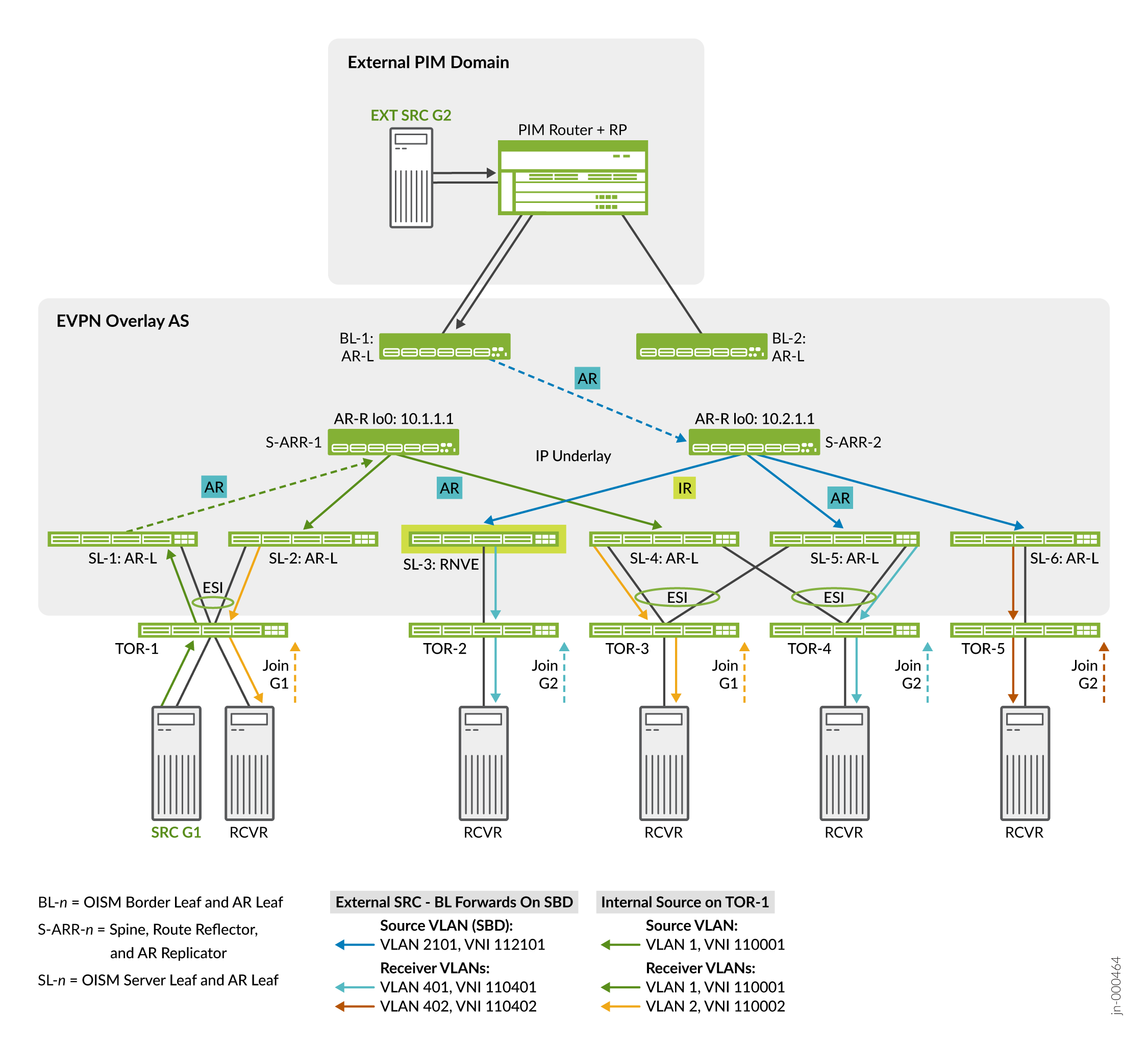
In the internal source use case:
SL-1 is the ingress device for an internal multicast stream from multihomed TOR-1 on source VLAN VLAN-1 for traffic to receivers in tenant VRF VRF-1.
SL-1 (a QFX5120 switch) forwards the traffic to its designated AR replicator for VLAN-1 (VNI 110001). The designated AR replicator is S-ARR-1 in this case.
S-ARR-1 replicates and forwards the stream on the source VLAN to the AR leaf devices that host TOR devices with subscribed receivers.
The destination SL devices forward or locally route the traffic to their subscribed receivers.
In the external source use case:
BL-1 is the ingress device for an external multicast stream from the external PIM domain for traffic to receivers in tenant VRF VRF-101.
BL-1 (a QFX5130 switch) forwards the traffic to its designated AR replicator for the SBD VLAN, VLAN-2101 (VNI 992101). The designated AR replicator is S-ARR-2 in this case.
S-ARR-2 replicates and forwards the stream on the SBD VLAN using AR tunnels to the AR leaf devices that host TORs with subscribed receivers.
S-ARR-2 also replicates the stream and uses an ingress replication (IR) tunnel to forward the stream to SL-3, an RNVE leaf device that hosts a TOR device with a subscribed receiver.
The destination SL devices forward or locally route the traffic toward their subscribed receivers.
For more details on AR device roles, how AR works, and other use cases besides the ones in this example, see Assisted Replication Multicast Optimization in EVPN Networks.
To configure AR in this example:
Verify OISM and AR Configuration and Operation
You can use the show commands in the following steps to verify OISM and AR configuration and operation.