Optimized Intersubnet Multicast (OISM) in EVPN Networks
Enable intersubnet multicast (OISM) to optimize multicast traffic routing and forwarding in an EVPN edge-routed bridging (ERB) overlay fabric. OISM avoids multicast data flooding to efficiently support scaled multicast environments. Also, with OISM your network can support multicast traffic flow among devices inside and outside of the EVPN fabric.
Overview of OISM
Traditional methods to support multicast traffic use ingress replication and flood multicast packets into the network to reach any interested listeners. Those methods don't scale well and have latency issues when your network has large multicast flows. Also, configuring the network to properly and efficiently handle multicast traffic from sources and to receivers outside of your network is complex.
Optimized intersubnet multicast (OISM) is a multicast traffic optimization feature that operates at Layer 2 (L2) and Layer 3 (L3) in EVPN-VXLAN edge-routed bridging (ERB) overlay fabrics. OISM solves many of the issues inherent in other multicast methods. The OISM design is based on the IETF draft specification https://datatracker.ietf.org/doc/html/draft-ietf-bess-evpn-irb-mcast.
We refer to our original OISM implementation as regular OISM. Regular OISM uses a symmetric bridge domains OISM model that requires you to configure all revenue VLANs (also called tenant VLANs) in the network on all OISM leaf devices.
Starting in Junos OS Release 23.4R1, we also support an enhanced version of OISM. Enhanced OISM uses an asymmetric bridge domains OISM model with which you don't need to configure all revenue VLANs in the network on all OISM devices. On each device, you can configure only the revenue VLANs that the device hosts. To support the asymmetric bridge domains model, enhanced OISM has some operational differences from the symmetric bridge domains model and small configuration differences. The differences are called out throughout this document.
You can apply OISM configuration and operation to multicast traffic but not to broadcast or unknown unicast traffic.
In EVPN ERB overlay fabric designs, the leaf devices in the fabric route traffic between tenant bridge domains (that is, between VLANs). When you enable OISM, the leaf devices route intersubnet multicast traffic locally through IRB interfaces using the control plane multicast states. With local routing between VLANs, the receiver IRB interface doesn't send the routed multicast traffic out into the EVPN core. The local routing model helps minimize the traffic load within the EVPN core. It also avoids traffic hairpinning.
OISM leaf devices also selectively forward traffic into the EVPN core only toward other EVPN devices with interested receivers. Selective forwarding further improves multicast traffic performance in the EVPN fabric.
With OISM enabled, ERB overlay fabrics can efficiently and effectively support multicast traffic flow between devices inside and outside the EVPN fabric. Without OISM, fabric designers must use the centrally routed bridging (CRB) overlay model to support multicast with external sources or receivers. OISM border leaf devices support different methods to route traffic to and from an external PIM domain. These methods use either integrated routing and bridging (IRB) interfaces or Layer 3 (L3) interfaces. OISM also employs a supplemental bridge domain (SBD) inside the fabric as follows:
-
The SBD has a different VLAN ID from any of the revenue VLANs.
-
Border leaf devices use the SBD to carry the traffic from external sources toward receivers within the EVPN fabric.
-
In enhanced OISM mode, server leaf devices use the SBD to carry traffic from internal sources to other server leaf devices in the EVPN fabric that are not multihoming peers. Enhanced mode leaf devices use the source VLAN only to send multicast traffic to their multihoming peer leaf devices.
- Benefits of OISM
- OISM Support in EVPN Instances
- OISM Support with Tenant L3 VRF Instances or the Default L3 Routing Instance
- OISM with Multicast Protocols and Other Multicast Optimizations in EVPN Fabrics
- Platform-Specific OISM Behavior with Regular OISM
Benefits of OISM
- Enables EVPN-VXLAN fabrics with the ERB overlay model to support multicast traffic with sources and receivers outside of the fabric.
- Minimizes multicast control packets and replicated data packets in the EVPN fabric core to optimize fabric multicast performance in scaled designs.
-
With enhanced OISM mode, you can further support scaled network designs with leaf devices that host a large number of diverse VLANs (on each leaf device, you need to configure only the VLANs that the device hosts).
OISM Support in EVPN Instances
We support OISM in EVPN-VXLAN fabrics in the following types of EVPN instances:
-
EVPN in the default switch instance (on platforms that support a default switch instance)
-
MAC-VRF EVPN routing instances with
vlan-awareandvlan-basedservice types only (see MAC-VRF Routing Instance Type Overview)
On Junos OS Evolved devices, we support EVPN-VXLAN using EVPN configurations with MAC-VRF instances only, and not in the default switch instance. As a result, on these devices we support OISM only in MAC-VRF EVPN instances.
OISM Support with Tenant L3 VRF Instances or the Default L3 Routing Instance
You can configure OISM with the following types of tenant L3 routing instances:
-
instance-type vrf, which are named virtual routing and forwarding (VRF) instances supported by all platforms that support OISM. OISM configurations usually include multiple tenant VRF instances. -
The default L3 routing instance on the device, supported only on some platforms. See Feature Explorer for currently supported platforms.
We support using the default L3 routing instance with:
-
Regular OISM mode on server leaf and border leaf devices, including border leaf devices acting in the PIM EVPN gateway (PEG) role (see Table 3).
-
IPv4 underlay peering in the EVPN network.
-
IPv4 multicast data traffic with IGMPv2, IGMPv3, and IGMP snooping.
-
PEG designated forwarder (DF) election options (see PEG DF Election).
Any use cases or behaviors that are not supported with OISM in a configured VRF instance on a particular platform are likewise not supported in the default L3 routing instance on that platform. For example, if we don't support assisted replication (AR) with OISM in a configured VRF on a platform, then we also don't support AR with OISM in the default L3 routing instance on that platform.
-
Throughout this OISM documentation, we describe configuring particular elements
in an L3 VRF instance on the EVPN and OISM devices. If your configuration uses
the default L3 routing instance instead of VRF instances, then you configure
those elements at the global level instead of at the [edit
routing-instances name ...] hierarchy level. For
example, substitute the configuration statements at this hierarchy level:
[edit routing-instances L3VRF-1 protocols evpn ...]
with the same statements at the global hierarchy level:
[edit protocols evpn ...]
In OISM configurations that use the default L3 routing instance, we also require that you add a global routing policy configuration to match overlay VXLAN interface next hops and avoid installing those routes for underlay reachability. With EVPN-VXLAN configurations, the VXLAN tunnels are resolved only in the underlay. The device overlay peering uses the underlay to establish reachability among the EVPN devices, which is a valid use of underlay routes. However, the device's underlay peering might use overlay IRB routes for reachability in default L3 routing instance configurations, which can cause routing loops in the network.
In this case, to prevent the underlay peering from using overlay routes for
underlay reachability on OISM devices, you must include defining and applying a
routing policy with the install-nexthop
except overlay-vxlan-interfaces policy statement action, as
follows:
set policy-options policy-statement policy-name term 1 then install-nexthop strict
set policy-options policy-statement policy-name term 1 then install-nexthop except overlay-vxlan-interfaces
set routing-options forwarding-table export policy-name
OISM with Multicast Protocols and Other Multicast Optimizations in EVPN Fabrics
OISM works with the following multicast protocols and other EVPN multicast optimization features.
Multicast Protocols Supported with OISM
-
IGMPv2, IGMPv3, and IGMP snooping for IPv4 multicast traffic
-
MLDv1, MLDv2, and MLD snooping for IPv6 multicast traffic
-
PIM, which facilitates both local routing and external multicast traffic routing
See the various OISM entries in Feature Explorer for specific platform and release support with the different multicast protocols.
OISM supports IGMP snooping with both IGMPv2 and IGMPv3 on the same device at the same time only under certain configuration constraints. Similarly, OISM supports MLD snooping with both MLDv1 and MLDv2 at the same time under the same configuration constraints. See IGMPv2 and IGMPv3 (or MLDv1 and MLDv2) in the Same EVPN-VXLAN Fabric for details.
Also see Supported IGMP or MLD Versions and Group Membership Report Modes for information on IGMP or MLD any-source multicast (ASM) and source-specific multicast (SSM) mode support in EVPN-VXLAN fabrics.
Other Multicast Optimization Features That Work with OISM
OISM works with these other multicast optimization features:
-
IGMP snooping or MLD snooping (some platforms) on the access side on the leaf devices.
With IGMP snooping or MLD snooping enabled, a leaf device that receives multicast traffic forwards it only toward other devices with interested receivers.
-
Multihoming support in an Ethernet segment (ES) using EVPN Type 7 (Join Sync) and Type 8 (Leave Sync) routes.
EVPN fabric devices advertise these route types to synchronize the multicast state among EVPN devices that are multihoming peers.
Note: ACX Series OISM leaf devices can be multihoming peer PE devices only with ACX Series devices. -
Selective multicast Ethernet tag (SMET) forwarding in the EVPN fabric core using EVPN Type 6 routes.
EVPN devices use Type 6 routes to limit forwarding within the EVPN core only to receivers interested in receiving traffic for a multicast group. You can use OISM to make this optimization work in EVPN ERB overlay fabrics. When you configure IGMP or MLD snooping, the fabric enables SMET forwarding with OISM automatically.
-
Assisted replication (AR) (some platforms and releases).
Table 1 lists how you can integrate AR into a fabric running OISM using the platforms and releases that support the different AR and OISM device roles. We support AR only with regular OISM on any platforms.
Table 1: AR Integrated with Regular OISM—Platform-Specific Supported Roles and Behavior Platforms Starting Release Supported Roles and Behavior EX4650
QFX5110
QFX5120
QFX10002 (except QFX10002-60C)
QFX10008
QFX10016
Junos OS Release 22.2R1
You can configure the AR leaf role on any of these devices that are also acting as OISM border leaf or server leaf devices.
QFX10002 (except QFX10002-60C)
QFX10008
QFX10016
Junos OS Release 22.2R1
You can configure any of these switches as AR replicators, in either of the following AR replicator modes:
-
Collocated mode: The device acts as both an AR replicator device and an OISM border leaf device.
-
Standalone mode: The device is an AR replicator but isn't also an OISM border leaf or server leaf device.
QFX5130
QFX5700
Junos OS Evolved Release 22.2R1
You can configure the AR leaf role on any of these devices that are also acting as OISM border leaf or server leaf devices.
You can configure these devices as AR replicators with OISM in standalone mode only. In standalone mode, the AR replicator device doesn't also operate as an OISM border leaf or server leaf.
EX4400
Junos OS Release 24.4R1
You can configure the AR leaf role on any of these devices that are also acting as OISM border leaf or server leaf devices.
These devices don't support the AR replicator role, and support the AR leaf role with other devices configured as standalone AR replicators only.
Note:We support AR with OISM on these devices only with VLAN-based and VLAN-aware MAC-VRF EVPN instances.
Note:ACX Series and PTX Series routers don't support AR with OISM as AR replicator or AR leaf devices.
See these references for more on using AR and OISM together:
- How AR works and how to configure AR—
Assisted Replication Multicast Optimization in EVPN Networks.
-
How AR integrates with OISM—AR with Optimized Intersubnet Multicast (OISM).
-
Use case illustrations of AR and OISM working together:
-
Platform-Specific OISM Behavior with Regular OISM
Use the following table to review platform-specific behaviors when running regular OISM for your platforms.
|
Platform |
Difference |
|---|---|
|
PTX10008 with the PTX10K-LC1301-36DD (Express 5) and PTX10K-LC1201-36CD (Express 4) line cards |
The device has a limitation in reporting multicast packet statistics when the device operates in interop chassis mode (both Express 5 and Express 4 line cards interoperating on the device), because Express 5 line cards don't support multicast snooping route counters. The multicast snooping route counters record the number of
packets that use a snooping route toward the destination.
Express 4 line cards update the snooping route counters, but
Express 5 line cards don't update those counters. As a
result, on devices running in interop mode, the packet
statistics reported in the |
Overview of Enhanced OISM
Enhanced OISM doesn't require you to configure all revenue bridge domains (VLANs) in the network on all OISM devices. On each device, you can configure only the revenue VLANs the device hosts. As a result, we describe this mode as having an asymmetric bridge domains (VLANs) model compared to the regular OISM mode where you must configure the revenue VLANs symmetrically on all leaf devices.
However, in enhanced OISM mode, you must still configure revenue VLANs symmetrically on the OISM leaf devices that share any Ethernet segments. In other words, you must configure the same revenue VLANs on OISM leaf devices that are multihoming peers for an attached multihomed host or multihomed customer edge (CE) device.
Enhanced OISM mode enables OISM to scale well when your network has leaf devices that host larger numbers of different VLANs per device.
- Enhanced OISM Support
- How to Enable Enhanced OISM
- When to Use Enhanced OISM
- Summary of Enhanced OISM Differences
Enhanced OISM Support
We support enhanced OISM with:
IGMPv2, IGMPv3, and IGMP snooping.
MLDv1, MLDv2, and MLD snooping (some platforms).
Note:ACX Series and PTX Series routers don't support enhanced OISM with MLD and MLD snooping for IPv6 multicast traffic.
MAC-VRF EVPN instance type only. See MAC-VRF Routing Instance Type Overview.
EVPN-VXLAN configurations with an IPv6 underlay for IPv4 or IPv6 multicast traffic (some platforms). See Enhanced OISM with an EVPN-VXLAN IPv6 Underlay Configuration.
Seamless data center interconnect (DCI) stitching between EVPN-VXLAN data centers configured with IPv4 or IPv6 underlay peering (some platforms). See EVPN-VXLAN DCI Multicast with Enhanced OISM.
-
Group based policy (GBP). We support GBP unicast flows and enhanced OISM flows seamlessly together across the VXLAN tunnels. You must configure GBP with the
vxlan-gbp-mc-profileGBP unified forwarding table (UFT) profile setting at the[edit chassis forwarding-options]hierarchy level.See GBP Profiles for more on GBP profiles and configurations.
Note:We don't assign GBP tags to multicast traffic. Only unicast traffic carries GBP tags in the VXLAN headers.
We don't support enhanced OISM with AR.
Search in Feature Explorer for "enhanced OISM" to see various entries there for platforms and releases in which enhanced OISM is supported with different multicast protocols and other features.
How to Enable Enhanced OISM
You enable enhanced OISM using the enhanced-oism option at the [edit
forwarding-options multicast-replication
evpn
irb] hierarchy level. You use this option instead of
the regular OISM mode oism option at the same hierarchy level.
The enhanced-oism and oism options are
mutually exclusive.
Besides the difference in configuring VLANs on the leaf devices and setting the OISM mode to use, the OISM components and configuration elements are the same for enhanced OISM as for regular OISM mode. However, this mode has some operational differences and small configuration differences to support the asymmetric bridge domains model. As a result, you must use the same OISM mode on all OISM devices in the network.
See:
Overview of OISM for a brief introduction to OISM support.
OISM Components for descriptions of all of the components and configuration elements involved in OISM operation.
When to Use Enhanced OISM
You can use enhanced OISM if all OISM devices in the network support this OISM mode. In that case, you might want to use enhanced OISM when:
Your network has a large number of revenue bridge domains (VLANs), and resources might be strained on some devices to configure all the VLANs there.
Your network has a large number of disjointed bridge domains (VLANs) in the network (different devices host different sets of VLANs).
On OISM devices in your network, you don't have policies configured that are based on the source MAC address of the packets. If you do have source MAC address policies, use regular OISM in your network instead.
Your network uses seamless DCI stitching to span more than one EVPN-VXLAN data center, and you want to optimize multicast traffic flow between the data centers instead of always flooding multicast traffic across the interconnection. The DCI gateway devices and OISM leaf devices in both networks must support seamless DCI multicast with enhanced OISM. (See EVPN-VXLAN DCI Multicast with Enhanced OISM.)
You might want to use regular OISM instead of enhanced OISM if your network needs to pass multicast packets with stringent requirements for decrementing the time-to-live (TTL) field. The enhanced OISM model inherently has a limitation where packets with TTL=1 will not reach receivers on devices that are not multihoming peers of the source device. Regular OISM forwards source traffic on the source VLAN and doesn't decrement the TTL value for destinations on the same VLAN. Alternatively, if you want to use enhanced OISM but avoid this limitation, we have a solution that enables enhanced OISM devices to forward multicast traffic on the source VLAN like regular OISM devices do. You can enable this solution for particular multicast groups (or groups and sources) using routing policies and a configuration option. See Enhanced OISM Exception Policy to Forward on Source VLAN Instead of SBD for Packets with TTL=1 for details.
Summary of Enhanced OISM Differences
Where applicable, the sections throughout this document describe any operational or configuration differences when you use enhanced OISM.
We summarize the main differences with enhanced OISM operation and configuration here.
- East-West Traffic from Internal Sources
- North-South Traffic from Internal Sources Toward External Receivers
- OSPF Area for Server Leaf Device Connectivity on the SBD
East-West Traffic from Internal Sources
The ingress leaf devices forward east-west multicast source traffic on the source VLAN to their multihoming peer leaf devices with which they share at least one Ethernet segment. For all other OISM leaf devices, they route the source traffic only on the SBD (even if those other devices host the source VLAN). Then each leaf device locally routes the traffic from the SBD to the destination VLAN.
This operation differs from the regular OISM mode, which sends multicast traffic from internal sources only on the source VLAN. Then each leaf device locally forwards the traffic on the source VLAN or routes the traffic from the source VLAN to the destination VLAN.
North-South Traffic from Internal Sources Toward External Receivers
The ingress leaf devices generate EVPN Type 10 Selective P-router Multicast Service Interface (S-PMSI) Auto-Discovery (A-D) routes for internal multicast (S,G) sources and groups.
The OISM border leaf devices act as PIM EVPN gateway (PEG) devices to connect to external multicast sources and receivers. The PEG devices need to perform PIM source registration only for multicast sources inside the EVPN network, so they look for and only do PIM registration for the sources in the advertised S-PMSI A-D routes.
OSPF Area for Server Leaf Device Connectivity on the SBD
On each of the server leaf devices, enhanced OISM requires that you include an OSPF area configuration for the SBD IRB interface in each tenant virtual routing and forwarding (VRF) instance. You configure the SBD IRB interface in OSPF active mode to establish OSPF adjacencies and support routing among the OISM leaf devices on the SBD. However, you set the OSPF interface priority to 0 so the SL devices don't ever assume the OSPF designated router (DR) or backup DR (BDR) role. You configure any other interfaces in the VRF instance in the OSPF area using OSPF passive mode, so they can exchange routing information but don't form OSPF adjacencies and participate in OSPF protocol processing.
OISM Components
The OISM environment includes:
Leaf devices in the EVPN fabric that function in border roles and server access roles.
External multicast sources and receivers in an external L3 PIM domain.
Bridge domain (VLAN) configurations that enable the fabric to route multicast traffic between internal and external devices.
The EVPN-VXLAN ERB overlay design includes lean spine devices that support L3 transit functions for the leaf devices. The lean spine devices don't usually perform any OISM functions.
The following sections describe these OISM components.
- OISM Device Roles
- PIM Domain with External Multicast Sources and Receivers
- Supported Methods for Multicast Data Transfer to or from an External PIM Domain
- OISM Bridge Domains (VLANs)
- Regular OISM Mode—Symmetric Bridge Domains Model
- Enhanced OISM Mode—Asymmetric Bridge Domains Model
- Configuration Elements for OISM Devices
OISM Device Roles
Figure 1 shows a simple EVPN-VXLAN ERB overlay fabric and the OISM device roles in the fabric.
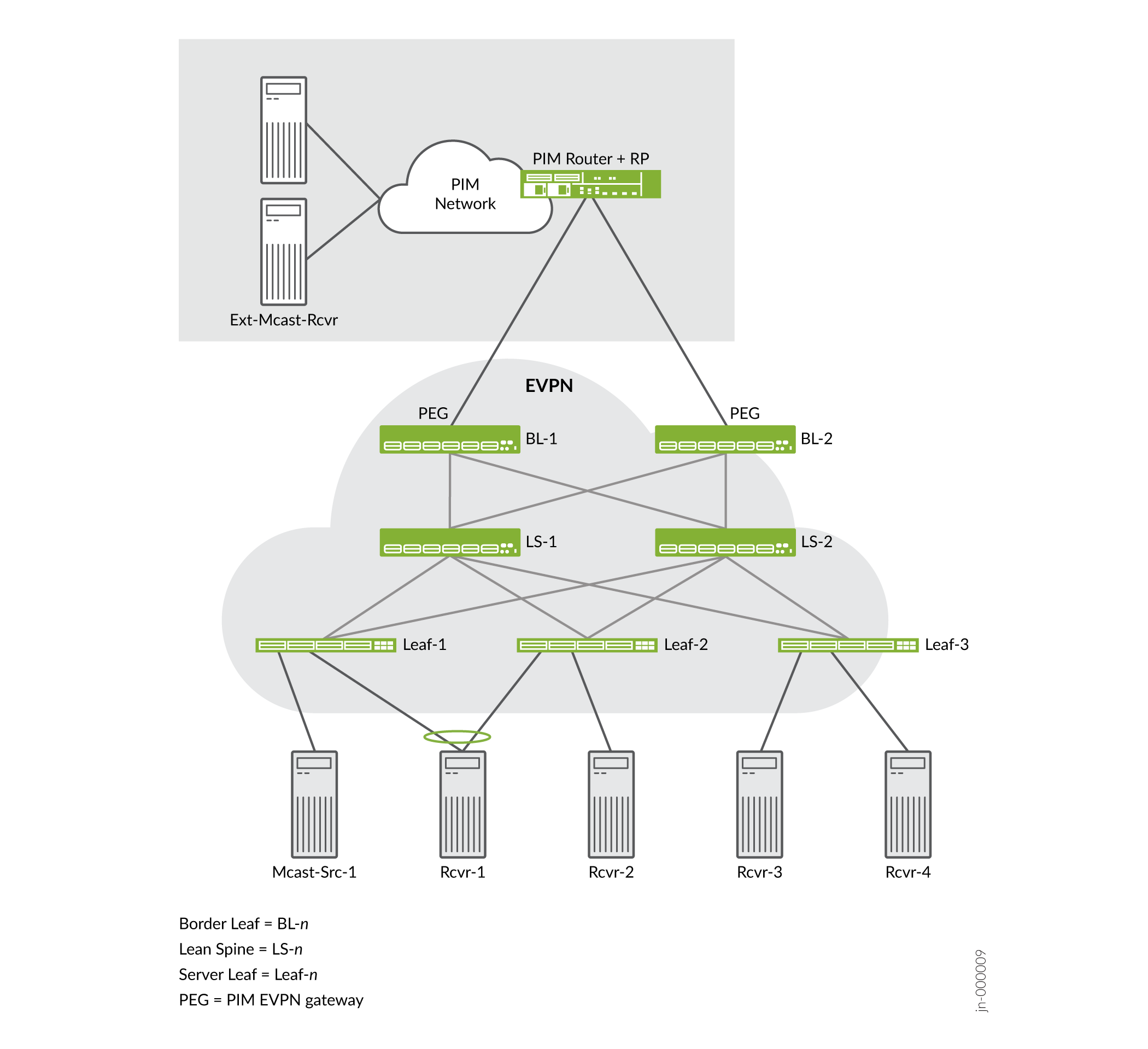
Table 3 summarizes the device roles.
| Device Role | Description |
|---|---|
Border leaf (BL) |
OISM leaf devices in the EVPN fabric underlay and overlay. Border leaf devices function as gateways interconnecting the EVPN fabric to multicast devices (sources and receivers) outside the fabric in an external PIM domain. These devices serve in the PIM EVPN gateway (PEG) role. |
Lean spine (LS) |
Spine devices in the underlay of the EVPN fabric. These devices usually operate as lean spines that support the EVPN underlay as IP transit devices. The lean spines might also act as route reflectors in the fabric. You configure OISM elements on the lean spine devices only in the following use cases:
|
Server leaf (Leaf) |
OISM leaf devices on the access side in the EVPN fabric underlay and overlay. Server leaf devices are often top-of-rack (ToR) switches. These devices connect the EVPN fabric to multicast sources and multicast receiver hosts on bridge domains or VLANs within the fabric. |
See Configuration Elements for OISM Devices for details on the configuration elements that are common and those that are different for each device role.
PIM Domain with External Multicast Sources and Receivers
In Figure 1, the OISM border leaf devices connect to multicast sources and receivers outside the EVPN fabric in a representative external PIM domain. The multicast devices in the external PIM domain follow standard PIM protocol procedures; their operation is not specific to OISM. External multicast traffic flows at L3 through the PIM domain.
You can use OISM to route and to forward multicast traffic in an EVPN-VXLAN ERB overlay fabric between devices in the following use cases:
Internal multicast sources and receivers
Internal multicast sources and external multicast receivers
External multicast sources and internal multicast receivers
For simplicity, in this documentation we represent the external PIM domain as:
A PIM router (a device such as an MX Series router) that doubles as the PIM rendezvous point (RP).
An external source.
An external receiver.
Supported Methods for Multicast Data Transfer to or from an External PIM Domain
OISM border leaf devices support one or more methods to route multicast traffic to and from devices outside of the fabric. Supported methods are platform-dependent.
Some platforms don't support the border leaf role. If you don't see a platform listed in Table 4 in the Supported Platforms column for any of the external multicast methods, that means the platform doesn't support the border leaf role.
| Name | Connection Method | Supported Platforms |
|---|---|---|
M-VLAN IRB method (also called L2 uplink with EVPN-enabled IRB interface) |
IRB interfaces on a multicast VLAN (M-VLAN) that you extend in the EVPN instance to create L2 uplinks to the external PIM domain. The fabric uses the M-VLAN and corresponding IRB interfaces only for external multicast traffic flow to and from the external PIM domain. This method supports EVPN Ethernet segment identifier (ESI) multihoming to connect the external PIM router to more than one OISM border leaf device in the fabric. |
PTX10001-36MR PTX10002-36QDD PTX10004 PTX10008 PTX10016 QFX5130* QFX5700* QFX10002 (except QFX10002-60C) QFX10008 QFX10016 *Supports this method in either regular or enhanced OISM mode. The other platforms support this method only in regular OISM mode. |
Classic L3 interface method |
Classic physical L3 interfaces on OISM border leaf devices that connect individually to the external PIM domain on different subnets. These interfaces aren't associated with a VLAN. You don't configure these interfaces in the EVPN instances. Instead, you assign IP addresses to these interfaces and include them in the tenant L3 VRF instances. Note:
The L3 interface connection can be an aggregated Ethernet (AE) interface bundle. |
ACX7024 ACX7100 ACX7332 ACX7348 ACX7509 EX4400 EX4650 PTX10001-36MR PTX10002-36QDD PTX10004 PTX10008 PTX10016 QFX5110 QFX5120 QFX5130 QFX5700 QFX10002 (except QFX10002-60C) QFX10008 QFX10016 |
Non-EVPN IRB method |
IRB interfaces on an extra VLAN that you don't extend in the EVPN instance. You include these logical interfaces in the tenant L3 VRF instances. On each border leaf device, you assign a unique extra VLAN ID and subnet for the associated IRB interface. We call this type of interface a non-EVPN IRB interface for external multicast. |
PTX10001-36MR PTX10002-36QDD PTX10004 PTX10008 PTX10016 QFX5130 QFX5700 |
See Overview of Multicast Forwarding with IGMP Snooping or MLD Snooping in an EVPN-VXLAN Environment for a general overview of connecting EVPN-VXLAN fabrics to an external PIM domain using an L2 M-VLAN or using L3 links.
OISM Bridge Domains (VLANs)
Table 5 summarizes the OISM bridge domains or VLANs and describes how OISM uses them.
References in this document to all OISM devices correspond to the border leaf and server leaf devices on which you enable OISM.
| Bridge Domain/VLAN | Description | Configure On: |
|---|---|---|
Multicast VLAN (M-VLAN) |
(M-VLAN IRB [L2 uplink with EVPN-enabled IRB interface] method for external multicast) A VLAN in the EVPN fabric with associated IRB interfaces that connect the fabric to an external multicast router as an L2 uplink. This VLAN and IRB interface enable traffic flow between devices inside and outside the fabric. To support IGMP snooping with both IGMPv2 and IGMPv3 traffic, you assign separate M-VLANs to carry traffic for each IGMP version. You extend this VLAN in the EVPN instance. You can also multihome the external multicast router to multiple border leaf device M-VLAN IRB interfaces in the same EVPN ES. The usual EVPN multihoming DF rules apply to send only one copy of the traffic in the ES on the M-VLAN. Configure the M-VLAN as a VLAN that is not the SBD or any of the revenue bridge domains in the EVPN fabric. Note:
See Supported Methods for Multicast Data Transfer to or from an External PIM Domain for all of the supported methods to connect to external sources and receivers, and which platforms can use each method. |
Border leaf devices |
Extra non-EVPN VLAN |
(Non-EVPN IRB method for external multicast) An extra VLAN that isn't in the EVPN instances in the fabric. You configure associated IRB interfaces in the tenant L3 VRF instances. This VLAN and IRB interface enable multicast traffic flow between devices inside the fabric and devices outside the fabric. You must assign distinct extra VLANs and corresponding IRB interface subnets on each border leaf device that are unique across the fabric. Also, to support IGMP snooping with both IGMPv2 and IGMPv3 traffic, use separate distinct extra non-EVPN VLANs to carry traffic for each IGMP version. The same constraints apply if you want to support MLD snooping with both MLDv1 and MLDv2 traffic. Note:
See Supported Methods for Multicast Data Transfer to or from an External PIM Domain for all of the supported methods to connect to external sources and receivers, and which platforms can use each method. |
Border leaf devices |
Revenue bridge domains (VLANs) |
Bridge domains for subscribers to the services that the fabric provides. You configure the revenue bridge domains as VLANs in the fabric. The revenue bridge domains correspond to the customer VLANs in the fabric. These VLANs are not specific to OISM, but the multicast sources and receivers in the fabric are in these bridge domains. For details on how to allocate VLANs for these bridge domains if you want to support IGMP snooping with both IGMPv2 and IGMPv3 receivers in the fabric, see IGMPv2 and IGMPv3 (or MLDv1 and MLDv2) in the Same EVPN-VXLAN Fabric. Note that the same constraints apply if you want to support MLD snooping with both MLDv1 and MLDv2 receivers. |
All OISM devices |
Supplemental bridge domain (SBD) |
Bridge domain that enables support for external multicast traffic, implements SMET optimization in the EVPN core, and supports the enhanced OISM mode implementation where all devices don't need to know all VLANs in the network. You configure the SBD as a regular VLAN that is different from the revenue bridge domain VLANs, the M-VLAN, or the extra non-EVPN VLANs. The SBD usually serves all OISM leaf devices in the fabric. To support IGMP snooping with both IGMPv2 and IGMPv3 traffic, or to support MLD snooping with both MLDv1 and MLDv2 traffic, you assign separate SBDs to carry traffic for each IGMP or MLD version. The SBD carries:
Note:
The SBD is central to OISM operation for:
The SBD IRB interface must always be up for OISM to work. You configure the VLAN that you want to use as the SBD for each L3 VRF instance, and configure a corresponding IRB interface. Use the |
All OISM devices |
Regular OISM Mode—Symmetric Bridge Domains Model
The regular OISM implementation uses a symmetric bridge domains model. We also refer to this OISM mode as the bridge domains everywhere (BDE) model. You configure all of the revenue bridge domains (VLANs) on all of the OISM devices in the network with this model.
In the symmetric bridge domains model, you must configure the SBD and all revenue bridge domains on all OISM border leaf and server leaf devices.
You also configure the following VLANs uniformly on the border leaf devices that connect to the external PIM domain:
The M-VLAN, if you use the M-VLAN IRB method for external multicast.
A unique extra non-EVPN VLAN on each border leaf device, if you use the non-EVPN IRB method for external multicast.
The lean spine devices in the fabric usually serve only as IP transit devices and possibly as route reflectors. As a result, you don't usually need to configure these elements on the lean spine devices. (See the Lean Spine row in Table 3 for some exceptions.)
Enhanced OISM Mode—Asymmetric Bridge Domains Model
The enhanced OISM implementation supports an asymmetric bridge domains model in which on each leaf device, you can configure only the revenue VLANs that the device hosts. As a result, we sometimes refer to enhanced OISM as the bridge domains NOT everywhere (BDNE) model.
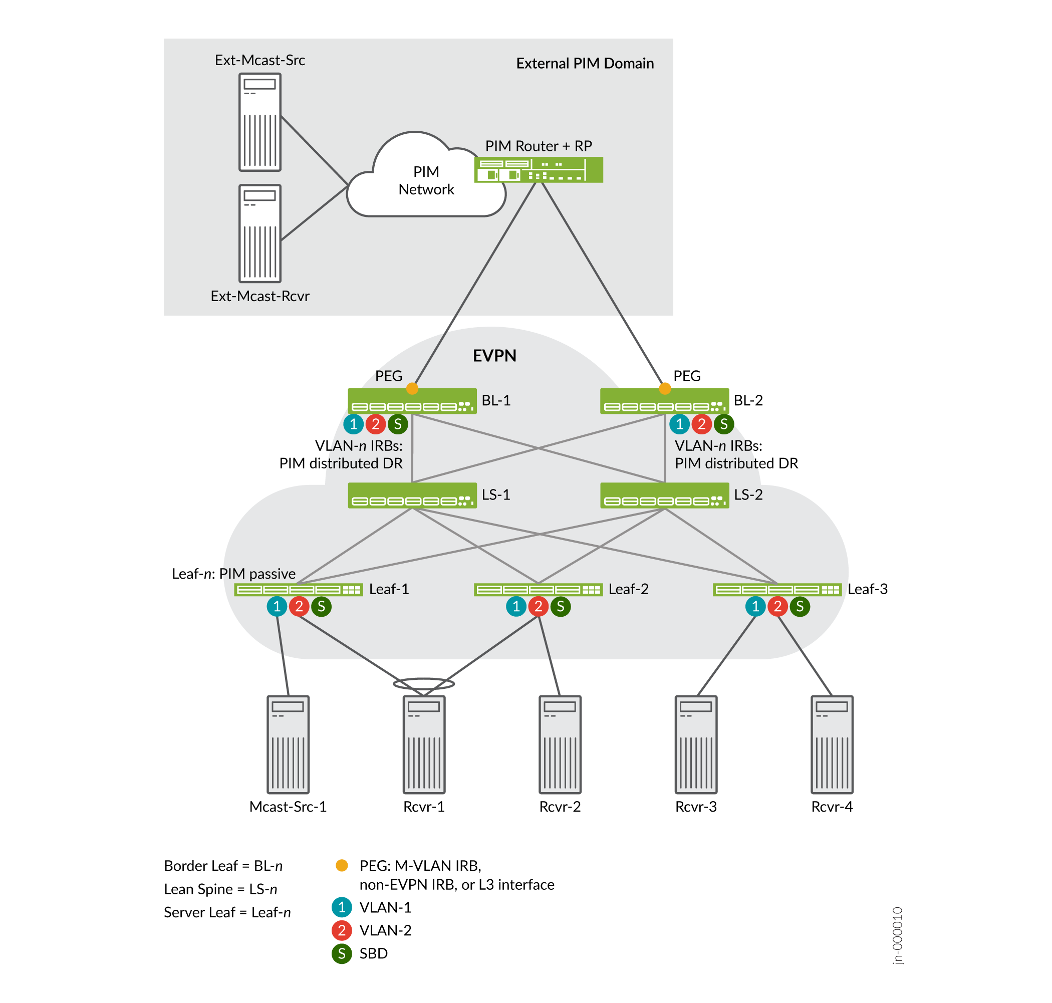
In general, enhanced OISM uses the same high-level OISM structure and network components you see in Figure 2, but with some operational differences to enable the asymmetric bridge domains model.
See Overview of Enhanced OISM for an introduction to the main differences from the regular OISM implementation. Throughout this document, we describe the operational or configuration differences when you use enhanced OISM instead of regular OISM, as applicable.
Configuration Elements for OISM Devices
This section summarizes the elements you need to configure on:
All OISM devices—Devices in the border leaf role and the server leaf role, and spine devices that also serve as AR replicators in standalone mode when you integrate AR with OISM.
See Table 6.
Server leaf devices only.
See Table 7.
Border leaf devices only, based on the method you use for external multicast:
M-VLAN IRB interface
Classic L3 interface
Non-EVPN IRB interface
See Table 8.
Some elements are optional, which the description notes.
EX4650, QFX5110, and QFX5120 switches support enterprise style interface configurations for OISM elements, but not service provider style interface configurations. For more information on these interface configuration styles, see Flexible Ethernet Services Encapsulation and Understanding Flexible Ethernet Services Support With EVPN-VXLAN.
Table 6 lists the elements you configure on all OISM devices.
| Configuration Element | Description |
|---|---|
OISM mode |
Enable OISM globally, and enable OISM routing functions in L3 VRF instances. You enable OISM in the regular mode or the enhanced mode, and all devices must run the same OISM mode. A device with OISM enabled advertises EVPN Type 3 Inclusive Multicast Ethernet Tag (IMET) routes as follows:
|
Revenue bridge domains (customer VLANs) and corresponding IRB interfaces |
Configure revenue bridge domains (customer VLANs) according to your data center services requirements. With regular OISM, you must configure all revenue bridge domain VLANs and corresponding IRB interfaces symmetrically on all OISM devices. With enhanced OISM, on each OISM device you need to configure only the revenue VLANs that the device hosts, along with the corresponding IRB interfaces. However, you must still configure the revenue VLANs symmetrically on any sets of multihoming peer leaf devices. See OISM Bridge Domains (VLANs) for more information. See IGMPv2 and IGMPv3 (or MLDv1 and MLDv2) in the Same EVPN-VXLAN Fabric for special considerations to configure the revenue bridge domains if you want to support:
|
SBD (VLAN) and corresponding IRB interface |
On all OISM devices, in each L3 VRF that supports OISM routing, configure a VLAN as the SBD and a corresponding IRB interface. The SBD can be any VLAN that is distinct from the M-VLAN, any of the non-EVPN VLANs, or any revenue bridge domain VLANs in the EVPN fabric. See OISM Bridge Domains (VLANs) for more information. To identify this VLAN as the SBD in the L3 VRF instance, configure the Starting in Junos OS and Junos OS Evolved 24.1R1, for interoperability with other vendors and compliance with the OISM draft standard, the EVPN Type 3 IMET routes for the SBD IRB interface include the OISM SBD flag in the multicast flags extended community. |
L3 multicast protocol—IGMPv2 or IGMPv3 |
Enable IGMPv2 or IGMPv3 L3 multicast protocols. Receivers send IGMP reports to express interest in receiving traffic for a multicast group. You can use IGMPv2 or IGMPv3 in any-source multicast (ASM) mode, or IGMPv3 in source-specific multicast (SSM) mode. Note that you can't enable IGMP snooping for both IGMP versions together for the same VLAN or in the same VRF instance with OISM enabled. However, to support IGMP snooping with IGMPv2 and IGMPv3 receivers in the same fabric, you can enable IGMP snooping with IGMPv2 for specific VLANs in one VRF instance, and enable IGMP snooping with IGMPv3 for other VLANs in another VRF instance. See IGMPv2 and IGMPv3 (or MLDv1 and MLDv2) in the Same EVPN-VXLAN Fabric for details. IGMPv2 is the default IGMP version. To configure IGMPv3, you must specify the |
L3 multicast protocol—MLDv1 or MLDv2 |
Enable MLDv1 or MLDv2 L3 multicast protocols if you have IPv6 multicast traffic in your fabric. Receivers send MLD reports to express interest in receiving traffic for a multicast group. You can use MLDv1 or MLDv2 in any-source multicast (ASM) mode, or MLDv2 in source-specific multicast (SSM) mode. Note that with OISM enabled, you can't enable MLD snooping for both MLD versions together for the same VLAN or in the same VRF instance. However, you can support MLD snooping with MLDv1 and MLDv2 receivers in the same fabric if you:
See IGMPv2 and IGMPv3 (or MLDv1 and MLDv2) in the Same EVPN-VXLAN Fabric for details. MLDv1 is the default MLD version. To configure MLDv2, you must specify the |
L2 multicast optimizations—IGMP snooping with SMET |
Enable IGMP snooping at L2 with IGMPv2 or IGMPv3 protocols as part of the optimizations OISM provides. With IGMP snooping, the device routes or forwards multicast traffic only toward interested access-side receivers. Receivers send IGMP reports to express interest in receiving traffic for a multicast group. When you enable IGMP snooping, the device also automatically advertises SMET Type 6 routes. With SMET, the device sends copies of the traffic into the EVPN core only toward other devices that have interested receivers. Configure IGMP snooping as follows:
|
L2 multicast optimizations—MLD snooping with SMET for IPv6 multicast traffic |
Enable MLD snooping at L2 with MLDv1 or MLDv2 protocols if you have IPv6 multicast traffic in the fabric. With MLD snooping, the device routes or forwards multicast traffic only toward interested access-side receivers. Receivers send MLD reports to express interest in receiving traffic for a multicast group. When you enable MLD snooping, the device also automatically advertises SMET Type 6 routes. With SMET, the device sends copies of the traffic into the EVPN core only toward other devices that have interested receivers. Configure MLD snooping as follows:
|
L3 VRF instance (or the default IRB routing instance) |
Configure one or more routing instances ( If your configuration has user-specified VRF instances, then
you configure the relevant L3 OISM routing functions at the
|
originate-smet-on-revenue-vlan-too |
(Optional) Enable the device to originate SMET Type 6 routes for revenue bridge domains (as well as on the SBD) upon receiving local IGMP or MLD reports. By default, OISM devices originate Type 6 routes only on the SBD. Use this option for compatibility with other vendor devices that don't support OISM. Those devices can't create the right states for the revenue bridge domain VLANs upon receiving Type 6 routes on the SBD. |
install-star-g-routes |
Enable the Routing Engine (RE) on the device to install (*,G) multicast routes on the Packet Forwarding Engine (PFE) for all of the revenue bridge domain VLANs in the routing instance immediately upon receiving an EVPN Type 6 route. Setting this option helps minimize traffic loss when multicast traffic first arrives. This option is mutually exclusive with the We require this option on:
Setting this option is generally not recommended in any use cases other than those listed above where it is required. See Latency and Scaling Trade-Offs for Installing Multicast Routes with OISM (install-star-g-routes Option) for details on how and when to set this option. |
conserve-mcast-routes-in-pfe |
(Required on ACX Series routers, QFX5130 switches, and QFX5700 switches when you configure those devices as OISM server leaf or OISM border leaf devices) Configure this option with OISM to conserve PFE table space. The device installs only the L3 multicast routes and avoids installing L2 multicast snooping routes. Don't set this option on QFX5130 and QFX5700 switches when you configure those
devices as standalone AR replicator devices with OISM. This
option is mutually exclusive with the
See ACX Series Routers, QFX5130 Switches, and QFX5700 Switches as Server Leaf and Border Leaf Devices with OISM for details. |
Table 7 lists the elements you configure on the server leaf devices.
| Configuration Element | Description |
|---|---|
PIM in passive mode on all revenue bridge domains and the SBD |
Configure this mode to facilitate local routing without all of the traditional PIM protocol functions. The server leaf device:
|
PIM with the |
This option enables an SBD IRB interface to accept multicast traffic from a source that isn't on the same subnet. The server leaf devices require this setting because:
|
OSPF in tenant VRFs for peer connectivity to support:
|
Configure OSPF in each tenant VRF so the server leaf devices learn routes:
The device creates the PIM (S,G) entries it needs to forward the traffic from the SBD to the revenue bridge domains. With regular OISM, on server leaf devices, you configure all interfaces in the L3 VRF instance in OSPF passive mode so these devices can share internal routes without forming OSPF adjacencies. With enhanced OISM only, on server leaf devices, you configure the SBD IRB interface in the L3 VRF instance in OSPF active mode. The SBD IRB interfaces need to establish OSPF adjacencies in this case because the server leaf devices exchange multicast traffic among themselves mostly on the SBD. You configure all other interfaces in the L3 VRF instance in OSPF passive mode. |
Table 8 lists the elements you configure on the border leaf devices based on the external multicast method you use.
| Configuration Element | External Multicast Method | Description |
|---|---|---|
M-VLAN and corresponding IRB interface (in EVPN instance) |
M-VLAN IRB (L2 uplink with EVPN-enabled IRB) method |
Configure a VLAN to serve as the M-VLAN, and extend this VLAN in the EVPN instance. This VLAN must be distinct from the SBD or any revenue bridge domain VLANs in the EVPN fabric. Also configure an M-VLAN IRB interface in the EVPN instance. See OISM Bridge Domains (VLANs) for more information about the M-VLAN. You can link multiple border leaf device M-VLAN IRB interfaces to the external multicast router in the same EVPN ES. The usual EVPN multihoming DF rules apply to prevent sending duplicate traffic on the M-VLAN. |
L2 multicast router interface on external multicast ports |
M-VLAN IRB (L2 uplink with EVPN-enabled IRB) method or non-EVPN IRB method |
Configure the With the M-VLAN IRB method, these interfaces support multicast traffic when the external domain router is multihomed to the border leaf devices. As a result, multihomed M-VLAN use cases require this configuration. This setting is also required with the non-EVPN IRB method. |
PIM on M-VLAN IRB interface |
M-VLAN IRB (L2 uplink with EVPN-enabled IRB) method |
Configure PIM in distributed designated router (DR) mode (distributed-dr) or standard PIM mode on an M-VLAN IRB interface. We recommend using distributed DR mode in most cases, especially on border leaf devices where the external PIM router is multihomed to multiple border leaf devices. The device uses PIM to:
You configure PIM on the M-VLAN IRB interface in the tenant VRF instances. similar to how you configure PIM on the revenue bridge domains. |
L3 physical interface with IP address |
Classic L3 interface |
Configure a physical L3 interface with an IP address for external multicast that connects the border leaf device to the external PIM domain at L3. Define the external multicast L3 interface in a different subnet on each border leaf device. Note:
The L3 interface connection can be an AE interface bundle. |
PIM on the logical interface for the external multicast physical L3 interface |
Classic L3 interface |
Configure the logical interface (unit 0) for the external multicast L3 interface in the tenant VRF instances. Configure standard PIM mode on the logical interface. With this setting, the border leaf device forms a PIM neighbor relationship with the external PIM router to send join messages and transmit or receive external multicast traffic. |
Extra VLAN and corresponding IRB interface (not in EVPN instance) |
Non-EVPN IRB method |
Configure an extra VLAN and IRB interface globally for external multicast without EVPN signaling. This VLAN and the IRB interface subnet must be distinct from the SBD, any revenue bridge domain VLANs, or the extra VLAN on any other border leaf device in the EVPN fabric. See OISM Bridge Domains (VLANs) for more about this extra VLAN and external multicast method. |
PIM on non-EVPN IRB interface |
Non-EVPN IRB method |
Configure PIM on the non-EVPN IRB interface in the tenant VRF instances. With this setting, the border leaf device forms a PIM neighbor relationship with the external PIM router to send join messages and transmit or receive external multicast traffic. |
PIM on SBD IRB interface |
All |
Configure standard PIM mode on the SBD IRB interface in the tenant VRF instances for SBD routing and forwarding. With this setting, the border leaf device:
|
PIM with the |
All |
(Enhanced OISM only) With this option, the border leaf device accepts multicast traffic from a source that isn't on the same subnet. We need this option because with enhanced OISM, you might not have configured all of the revenue VLANs on all of the OISM devices. Including this option enables border devices to have routes to a multicast source located behind other OISM leaf devices when the source is on a VLAN that isn't also configured on the border leaf device. |
PIM EVPN gateway (PEG) role |
All (include the external IRB option for EVPN, |
Configure the pim-evpn-gateway role on the border leaf device to connect to the external PIM router. In this role, the border leaf device uses traditional PIM routing behavior and does local routing, as follows: For externally-sourced traffic:
For internally-sourced traffic:
EVPN IMET routes for PEG interfaces include the OISM PEG flag in the multicast flags extended community field of the route. |
OSPF for:
|
All |
Configure an OSPF area in the tenant L3 VRF instance so the border leaf device learns routes to the multicast sources. The device requires these routes to support forwarding multicast traffic:
The device needs this route information to create the PIM (S,G) entries to forward the traffic on the external multicast interfaces, the SBD, and the revenue bridge domains. (Enhanced OISM) The border leaf devices also need to learn the routes for east-west traffic on the SBD among the leaf devices that aren't multihoming peers. As a result, with either regular OISM or enhanced OISM, on border leaf devices, you configure OSPF in active mode on:
You configure any other interfaces in the L3 VRF instance in OSPF passive mode. |
PIM distributed DR mode on revenue bridge domain IRB interfaces |
All |
Configure PIM in distributed DR mode (distributed-dr) on the revenue bridge domain IRB interfaces in the tenant VRF instances. In this mode, the border leaf device:
|
PIM accept-join-always-from option and policy on M-VLAN IRB interface |
M-VLAN IRB (L2 uplink with EVPN-enabled IRB) method | Set this option on the M-VLAN IRB interface in the tenant VRF instances when the external PIM router is multihomed to more than one EVPN border leaf device. With this option, the device can accept and install the same PIM (S,G) join states on multihoming peer border leaf devices. This option supports sending multicast traffic from sources inside the fabric to receivers in the external PIM domain. With multihoming on the M-VLAN, the usual EVPN multihoming DF rules apply in an ES to prevent sending duplicate traffic. If peer border leaf devices have the same valid join states in place, any device that is the EVPN DF can forward the multicast traffic. Configure this statement with policies that specify the interface should always install PIM joins from upstream neighbor addresses that correspond to the external PIM router. Note:
You don't use this option with the classic L3 interface and non-EVPN IRB methods. Those methods don't extend the external multicast interfaces in the EVPN instance. |
See the following sections for more details on configuring OISM devices:
Configure Common OISM Elements on Border Leaf Devices and Server Leaf Devices
Configure Border Leaf Device OISM Elements with M-VLAN IRB Method
Configure Border Leaf Device OISM Elements with Classic L3 Interface Method
Configure Border Leaf Device OISM Elements with Non-EVPN IRB Method
For a full OISM configuration example of a data center fabric use case that includes classic L3 interface connections to the external PIM domain, see Optimized Intersubnet Multicast (OISM) with Assisted Replication (AR) for Edge-Routed Bridging Overlays.
How OISM Works
The following sections describe how OISM works and show how the multicast traffic flows in several common use cases with the symmetric bridge domains OISM model.
The use cases we support with enhanced OISM (the asymmetric bridge domains model) are similar to those in this section, but with a few operational differences. Also, as mentioned previously, you don't need to configure all VLANs on all leaf devices as the figures in this sections show.
For an overview of the differences with enhanced OISM, see Overview of Enhanced OISM. For more details on the operational differences, see How Enhanced OISM Works.
- Local Routing on OISM Devices
- Multicast Traffic Forwarding and Routing with Source and Receivers Inside the EVPN Data Center
- Multicast Traffic From an Internal Source to Receivers Outside the EVPN Data Center—M-VLAN IRB Method
- Multicast Traffic from an Internal Source to Receivers Outside the EVPN Data Center—L3 Interface Method or Non-EVPN IRB Method
- Multicast Traffic from an External Source to Receivers Inside the EVPN Data Center—M-VLAN IRB Method
- Multicast Traffic from an External Source to Receivers Inside the EVPN Data Center—L3 Interface Method or Non-EVPN IRB Method
- AR and OISM with an Internal Multicast Source
- AR and OISM with an Internal Multicast Source and Multihomed Receiver
- AR and OISM with an External Multicast Source
Local Routing on OISM Devices
In Figure 3, we illustrate how local routing and forwarding works in general on OISM devices. As the figure shows, OISM local routing forwards the traffic on the source VLAN. Each leaf device routes the traffic locally to its receivers on other VLANs, which avoids hairpinning for intersubnet routing on the same device.
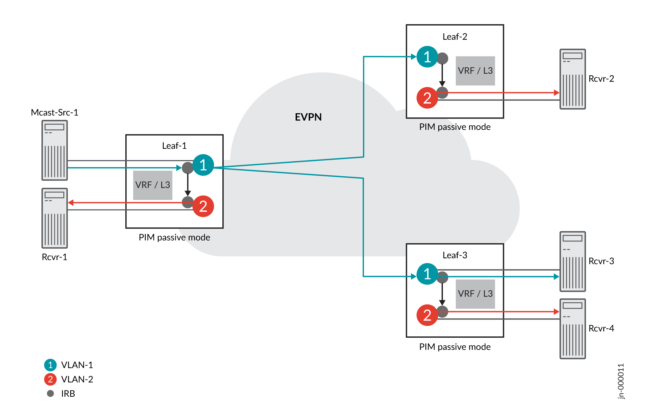
In this case, the source traffic comes from Mcast-Src-1 on VLAN-1, the blue VLAN. Server leaf devices use IRB interfaces and PIM in passive mode to route traffic between VLANs. With PIM in passive mode, server leaf devices:
Don’t become PIM neighbors with the other leaf devices.
Act as a local PIM RP, create local PIM state upon receiving IGMP or MLD reports, and avoid doing source registration.
As a result, the server leaf devices forward and route multicast traffic within the fabric as follows to receivers interested in the multicast group:
The ingress leaf device (Leaf-1) forwards the traffic on the source VLAN into the EVPN fabric toward the other leaf devices with interested receivers.
All of the server leaf devices don't need to forward the traffic back into the EVPN core to another device that is a designated router. Server leaf devices can locally:
Forward the traffic on the source VLAN toward local interested receivers on the source VLAN.
Route the traffic from the source VLAN through the IRB interfaces toward local interested receivers in other VLANs.
Multicast Traffic Forwarding and Routing with Source and Receivers Inside the EVPN Data Center
When the multicast source is inside the EVPN fabric, the server leaf devices receive the multicast traffic on the source VLAN. Then they locally route or forward the traffic as described in Local Routing on OISM Devices.
The following figure illustrates OISM local routing and forwarding within an EVPN fabric in detail. The figure also shows how local routing works with EVPN multihoming for a multicast receiver.
In Figure 4, the multicast source, Mcast-Src-1, is single-homed to Leaf-1. The source VLAN is VLAN-1 (the blue VLAN). Multicast control and data traffic flow proceeds as follows:
Receivers on all three server leaf devices sent IGMP or MLD reports (join messages) expressing interest in receiving the traffic for a multicast group.
Leaf-1 forwards the traffic on the source VLAN to both Leaf-2 and Leaf-3 because both leaf devices have interested receivers. In this case, the receivers on Leaf-2 and Leaf-3 use single-homing.
Leaf-2 and Leaf-3 forward or locally route the traffic to their interested receivers (Rcvr-2, Rcvr-3, and Rcvr-4) as described in Local Routing on OISM Devices.
Rcvr-1 on VLAN-2 is multihomed to Leaf-1 and Leaf-2 in an EVPN ES. Rcvr-1 has expressed interest in receiving the multicast traffic, so:
- Both server leaf devices, Leaf-1 and Leaf-2, receive the IGMP or MLD report.
- Both Leaf-1 and Leaf-2 locally route the traffic from the source VLAN (VLAN-1) because each device has the PIM passive mode configuration.
- However, because Leaf-1 is the DF for the EVPN ES, only Leaf-1 forwards the traffic to Rcvr-1.
The border leaf devices receive the multicast traffic through the EVPN fabric on the source VLAN. Note that the border leaf devices could have local receivers, although we don't show that case. With local receivers, the device also locally routes or forwards the traffic to those receivers the same way the server leaf devices do.
Figure 4 also shows that the border leaf devices locally route the traffic from the source VLAN toward any external multicast receivers in the external PIM domain. See Supported Methods for Multicast Data Transfer to or from an External PIM Domain for the available external multicast methods by platform. Later sections describe the multicast control and data traffic flow for external source and external receiver use cases.
Multicast Traffic From an Internal Source to Receivers Outside the EVPN Data Center—M-VLAN IRB Method
In Figure 5, we illustrate the OISM use case where a multicast source inside the EVPN fabric sends multicast traffic to an interested receiver outside the fabric using the M-VLAN IRB (L2 uplink with EVPN-enabled IRB) method for external multicast. (Supported Methods for Multicast Data Transfer to or from an External PIM Domain lists external multicast method support by platform.)
The border leaf devices you configure in the OISM PEG role receive the multicast traffic on the source VLAN through the EVPN core. Then the border leaf devices replicate the traffic and route it onto the M-VLAN toward the external PIM domain to reach the external receiver.
PEG border leaf devices only send multicast source traffic received on the revenue bridge domains to the M-VLAN. These devices don't forward the traffic back into the EVPN core toward the other border leaf devices.
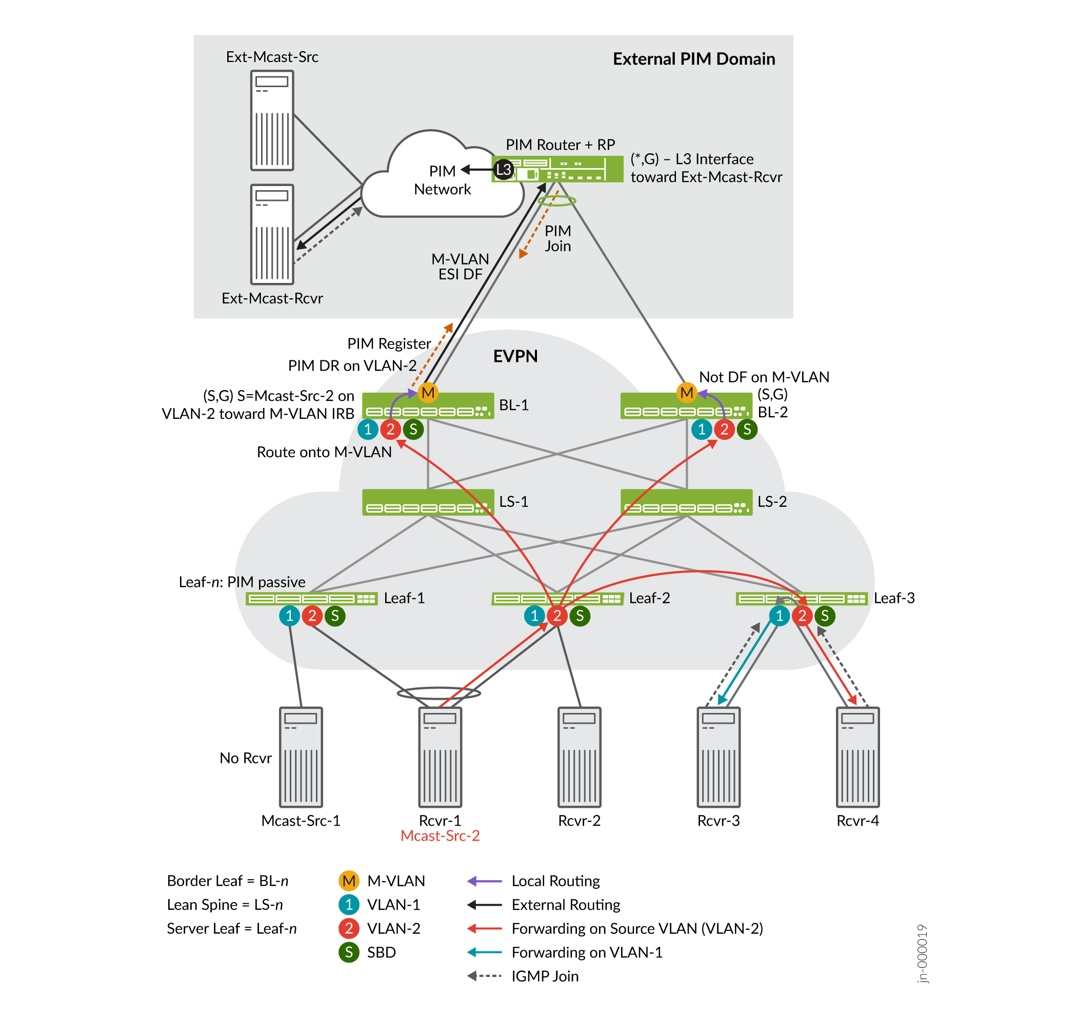
In Figure 5, the internal source for a multicast group is Mcast-Src-2, the same device as Rcvr-1, which is multihomed to Leaf-1 and Leaf 2. The source sends the multicast traffic on VLAN-2. The external receiver, Ext-Mcast-Rcvr, expresses interest in receiving the multicast traffic for that multicast group (sends a join message). Internal receivers Rcvr-3 (on VLAN-1) and Rcvr-4 (on VLAN-2) also request to join the multicast group and receive the traffic.
Note that the PIM router is multihomed to both BL-1 and BL-2, the PEG devices, in the EVPN fabric. Those connections are in the same ES; the DF election process chooses one of these devices as the DF for the ES. Only the DF will forward traffic (on the M-VLAN) toward external receivers.
The source traffic reaches the interested internal and external receivers as follows:
- Traffic Flow from Multihomed Source to Internal Receivers
- Traffic Flow to External Receiver—M-VLAN IRB Method
Traffic Flow from Multihomed Source to Internal Receivers
These steps summarize the multicast control and data traffic flow from the multihomed source to the internal receivers:
Mcast-Src-2 (also labeled Rcvr-1) originates the traffic on VLAN-2, the red VLAN. Because the device is multihomed to Leaf-1 and Leaf-2, the device hashes the traffic on VLAN-2 to one of those server leaf devices. In this case, Leaf-2 receives the traffic.
The red arrows show that Leaf-2 forwards the traffic on the source VLAN, VLAN-2, only to:
The other server leaf devices with interested receivers—In this case, only Leaf-3.
The border leaf devices, which both act in the OISM PEG role.
Note that no receivers behind Leaf-1 or Leaf-2 sent an IGMP report to join the multicast group. With IGMP snooping and SMET forwarding enabled, Leaf-2 doesn't forward the traffic to Leaf-1 because Leaf-1 has no interested receivers. Leaf-2 also doesn't locally route the traffic to Rcvr-2 for the same reason.
Leaf-3 receives the source traffic on VLAN-2. Then Leaf-3 routes the traffic locally to VLAN-1 to Rcvr-3. Leaf-3 also forwards the traffic to Rcvr-4 on VLAN-2.
Both border leaf devices BL-1 and BL-2 also receive the source traffic from the EVPN core. We describe the external multicast flow next.
Traffic Flow to External Receiver—M-VLAN IRB Method
These steps summarize the multicast control and data traffic flow in Figure 5 from the border leaf devices toward the external receiver using the M-VLAN IRB method:
In the external PIM domain, the PIM RP enters a PIM (*,G) multicast routing table entry. The entry includes the L3 interface toward Ext-Mcast-Rcvr as the downstream interface.
Both border leaf devices BL-1 and BL-2 receive the source traffic from the EVPN core. The IRB interface on VLAN-2 on one of these border leaf devices is the PIM DR for VLAN-2. In this case, the PIM DR is on BL-1, so BL-1 sends a PIM Register message toward the PIM RP on the M-VLAN IRB interface.
The PIM RP sends a PIM Join message back toward BL-1. BL-1 creates an (S,G) multicast routing table entry as follows:
- The source address is the IP address of Mcast-Src-2 in VLAN-2.
- The downstream interface is the M-VLAN IRB interface.
Both BL-1 and BL-2 are PEG devices and configured in PIM distributed DR mode for the revenue bridge domain (VLAN-1 and VLAN-2) IRB interfaces. As a result, both BL-1 and BL-2 receive the PIM Join and create a similar (S,G) state. Both devices route the traffic locally from VLAN-2 to the M-VLAN.
However, only the DF for the M-VLAN ES actually forwards the data on the M-VLAN to the external PIM domain. In this case, BL-1 is the DF and sends the traffic toward the external receiver. (See the label "M-VLAN ESI DF" and the black arrow between BL-1 and the PIM router in Figure 5.)
The PIM RP receives the traffic from the OISM M-VLAN IRB interface connection. The PIM router sends the traffic to an L3 interface toward the external receiver.
Multicast Traffic from an Internal Source to Receivers Outside the EVPN Data Center—L3 Interface Method or Non-EVPN IRB Method
In Figure 6, we illustrate the OISM use case where a multicast source inside the EVPN fabric sends multicast traffic to a receiver outside the fabric using either of the following methods for external multicast:
Classic L3 interface external multicast method:
On each border leaf device, you configure a classic L3 interface with family
inetthat connects to the external PIM router. You assign an IP address to that interface on a different subnet than the L3 interface subnets on other border leaf devices in the fabric.You enable PIM on the interface and include the interface in the tenant VRF instances that have multicast data receivers. This method differs from the M-VLAN IRB method because you don't extend this interface in the EVPN instance.
Note:The L3 interface connection here can be an individual physical interface or an AE interface bundle that includes multiple physical L3 interfaces.
Non-EVPN IRB external multicast method:
On each border leaf device, you configure a unique extra VLAN that is only for external multicast. You also configure a corresponding L3 IRB interface with an IP address that connects to the external PIM router. The extra VLAN ID can't be the same as the VLAN ID of the revenue bridge domains, SBD, or extra VLAN on any other border leaf device in the fabric. In addition, similar to the L3 interface method, the non-EVPN IRB interfaces on different border leaf devices should connect to the PIM router on different subnets in the fabric.
You enable PIM on the IRB interface and include the interface in the tenant VRF instances that have multicast data receivers. This method differs from the M-VLAN IRB method because you don't extend this VLAN or IRB interface in the EVPN instance.
Supported Methods for Multicast Data Transfer to or from an External PIM Domain lists the platforms that support these external multicast methods.
Figure 6 includes the same internal multihomed source, internal receivers, and an external receiver as in Multicast Traffic From an Internal Source to Receivers Outside the EVPN Data Center—M-VLAN IRB Method. See the steps in Traffic Flow from Multihomed Source to Internal Receivers for details on the internal multicast traffic flow. In this section we describe only what's different in this case, which is the multicast traffic flow from the border leaf devices to the external receiver.
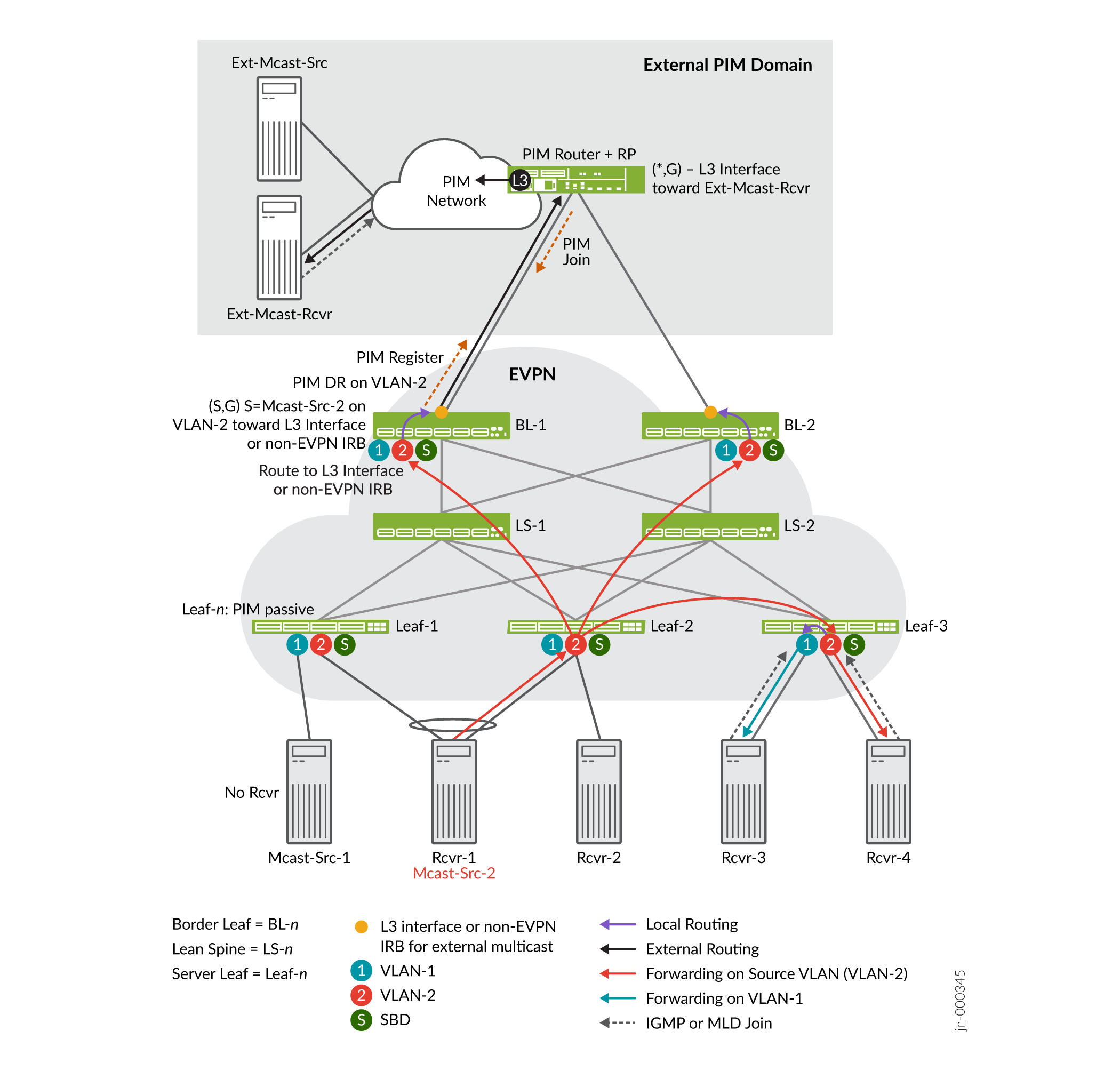
In Figure 6, the internal source for a multicast group is Mcast-Src-2, which is multihomed to Leaf-1 and Leaf-2. The source sends the multicast traffic on VLAN-2, the red VLAN. The external receiver, Ext-Mcast-Rcvr, expresses interest in receiving the multicast traffic for that multicast group (sends a join message).
The external multicast flow in this use case is very similar to the M-VLAN IRB use case. The border leaf devices in the OISM PEG role receive the multicast traffic on the source VLAN through the EVPN core. However, the main difference in this case is that the external multicast interfaces don't use EVPN signaling and don't share an ESI across the border leaf devices. The external multicast interfaces on each border leaf device are distinct, and each have L3 reachability to the external PIM gateway router. The border leaf device that establishes the PIM join state replicates and sends the traffic on the L3 interface or non-EVPN IRB interface to the external PIM domain with the external receiver.
PEG border leaf devices only send multicast source traffic received on the revenue bridge domains to the external PIM domain. These devices don't forward the traffic back into the EVPN core toward the other border leaf devices.
The following section explains how the source traffic reaches the interested external receiver.
Traffic Flow to External Receiver—L3 Interface or Non-EVPN IRB Method
These steps summarize the multicast control and data traffic flow in Figure 6 from the border leaf devices toward the external receiver using the classic L3 interface method or the non-EVPN IRB method:
In the external PIM domain, the PIM RP enters a PIM (*,G) multicast routing table entry. The entry includes the L3 interface toward Ext-Mcast-Rcvr as the downstream interface.
Both border leaf devices BL-1 and BL-2 receive the source traffic from the EVPN core on VLAN-2. The IRB interface on VLAN-2 on one of these border leaf devices is the PIM DR for VLAN-2. In this case, the PIM DR is on BL-1, so BL-1 sends a PIM Register message toward the PIM RP on its external multicast L3 interface or non-EVPN IRB interface.
The PIM RP sends a PIM Join message back toward BL-1. BL-1 receives the PIM join and creates an (S,G) multicast routing table entry as follows:
- The source address is the IP address of Mcast-Src-2 in VLAN-2.
- The downstream interface is the external multicast L3 interface or the non-EVPN IRB interface.
BL-1 routes the traffic from VLAN-2 to its external multicast L3 interface or non-EVPN IRB interface.
The PIM RP receives the traffic from BL-1 on the external multicast interface. The PIM router sends the traffic to an L3 interface toward the external receiver. The external receiver receives the multicast traffic.
Multicast Traffic from an External Source to Receivers Inside the EVPN Data Center—M-VLAN IRB Method
Figure 7 illustrates the OISM use case where a multicast source outside the EVPN fabric sends multicast traffic to receivers inside the fabric. This use case exhibits the two main ways OISM uses the SBD in the EVPN core:
To carry external multicast source traffic.
To advertise SMET Type 6 routes.
The Type 6 routes ensure that the border leaf devices only forward the traffic toward the EVPN devices with interested receivers.
OISM border leaf devices receive external multicast source traffic through the M-VLAN IRB interfaces. OISM devices use the SBD to forward traffic toward EVPN server leaf devices with interested receivers on the revenue bridge domains. Each leaf device then locally forwards or routes the traffic on the revenue bridge domains to its local receivers.
This use case has an internal receiver that is multihomed to two server leaf devices.
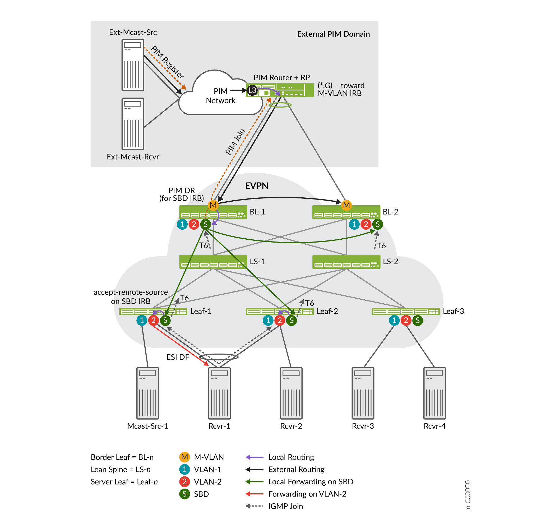
In Figure 7, Rcvr-1 within the EVPN fabric is multihomed to server leaf devices Leaf-1 and Leaf-2. Rcvr-1 expresses interest in receiving traffic from a multicast group. The source for the multicast traffic for the group is Ext-Mcast-Src in the external PIM domain.
The external source traffic reaches the interested multihomed receiver, Rcvr-1, as follows:
- Multicast Control Flow between the Internal Multihomed Receiver and the External Source—M-VLAN IRB Method
- Traffic Flow from the Border Leaf Devices to Internal Receivers—M-VLAN IRB Method
- What Happens When a Multihomed External PIM Router Load-Balances the Traffic—M-VLAN IRB Method
- What Happens with Local Receivers on Border Leaf Devices—M-VLAN IRB Method
Multicast Control Flow between the Internal Multihomed Receiver and the External Source—M-VLAN IRB Method
These steps summarize the multicast control flow in this use case:
Rcvr-1 sends an IGMP join message to both multihoming peers Leaf-1 and Leaf-2.
Both Leaf-1 and Leaf-2 generate an EVPN Type 6 route toward the EVPN core on the SBD. The Type 6 (SMET) route advertises that Rcvr-1 is interested in the multicast data.
Both border leaf devices BL-1 and BL-2 receive the Type 6 route on the SBD.
The Type 6 route (on the SBD) signals the border leaf devices to create a PIM join toward the PIM RP (reachable through the M-VLAN). However, to avoid duplicate join messages, only the border leaf device that is the PIM DR for the SBD generates the PIM join message. In this case, the figure shows the PIM DR for the SBD is BL-1. BL-1 sends the PIM join message toward the PIM RP by way of its neighbor, the M-VLAN IRB interface.
The PIM RP receives the join message. Then the PIM RP creates a PIM (*,G) entry in the multicast routing table with the M-VLAN IRB interface as the downstream interface.
The external source Ext-Mcast-Src registers with the PIM RP. The PIM RP has a multicast route for the group with the M-VLAN IRB interface as the downstream interface. As a result, the PIM RP routes the multicast traffic coming in at L3 onto its connection to the M-VLAN IRB toward BL-1 or BL-2. In this case, BL-1 sent the PIM join, so BL-1 receives the traffic on its M-VLAN IRB interface.
Traffic Flow from the Border Leaf Devices to Internal Receivers—M-VLAN IRB Method
In Figure 7, BL-1 is the PIM DR for the SBD and sent the PIM join toward the external PIM domain. BL-1 receives and routes (or forwards) the external source traffic as follows:
BL-1 routes the traffic locally from the M-VLAN to the SBD on its SBD IRB interface because BL-1 is the PIM DR for the SBD. See the small gray arrow from the M-VLAN to the SBD on BL-1.
BL-1 forwards a copy of the traffic on the M-VLAN toward BL-2 because both border leaf devices are in the PEG role. See the black arrow from BL-1 toward BL-2.
As a PEG device using the M-VLAN IRB method, BL-2 expects to receive external multicast traffic only on the M-VLAN IRB interface. If BL-2 has any local receivers, BL-2 can receive the traffic and route it locally to those receivers.
BL-1 also forwards a copy of the traffic on the SBD into the EVPN core to BL-2. See the green arrow from BL-1 toward BL-2.
BL-2 drops the traffic because again, as a PEG device using the M-VLAN IRB method, BL-2 expects to receive external source traffic only on the M-VLAN IRB interface. BL-2 doesn't expect external source traffic on the SBD IRB interface from BL-1. In other words, BL-2 sees this case as a source interface mismatch (a reverse path forwarding [RFP] failure).
Note:One reason why the ingress border leaf device also forwards a copy on the SBD to other border leaf devices is to ensure that another border leaf device can receive external source traffic if its M-VLAN interface is down. Then any interested local receivers on the other border leaf device can still get the traffic.
BL-1 selectively forwards copies of the traffic on the SBD to the server leaf devices with interested receivers, based on the advertised Type 6 routes.
In this case, Leaf-1 and Leaf-2 have a multihomed interested receiver, Rcvr-1, on VLAN-2. As a result, BL-1 sends the traffic toward both leaf devices. See the green arrows from BL-1 toward Leaf-1 and Leaf-2.
Note:In a similar use case with the PIM router multihomed to BL-1 and BL-2, BL-1 might receive the external multicast source traffic, but BL-2 is the PIM DR on the SBD. One reason why BL-1 forwards the incoming external multicast traffic toward BL-2 on the M-VLAN is so that BL-2 can handle this use case. See the black arrow from BL-1 toward BL-2 on the M-VLAN in Figure 7. If BL-2 is the PIM DR on the SBD, upon receiving the traffic on the M-VLAN from BL-1, BL-2 forwards the traffic on the SBD toward Leaf-1 and Leaf-2. In this case, the green arrows in the figure would flow from BL-2 toward the other EVPN devices instead of flowing from BL-1.
Leaf-1 and Leaf-2 locally route the traffic from the SBD IRB interface to the revenue bridge domain IRB interface for VLAN-2 toward the interested (multihomed) receiver. However, with EVPN multihoming, only the EVPN DF in the ES forwards the traffic toward Rcvr-1 so Rcvr-1 doesn't get duplicate traffic.
In this case, Leaf-1 is the EVPN DF, so only Leaf-1 forwards the traffic to Rcvr-1.
What Happens When a Multihomed External PIM Router Load-Balances the Traffic—M-VLAN IRB Method
In Figure 7, the external PIM gateway router is multihomed to BL-1 and BL-2 on an ES in the EVPN fabric. If the pair of connections on the PIM router side is an AE interface bundle, the PIM router does load balancing among the interfaces in the bundle. In that case, both BL-1 and BL-2 will each receive some of the multicast traffic flow from the external source. However, all receivers should receive all of that traffic. For simplicity, the figure doesn't show traffic arrows for this load balancing, but we'll describe the flow here.
BL-1 and BL-2 each receive part of the external multicast source traffic on their M-VLAN IRB interfaces. However, because BL-1 is the PIM DR on the SBD, only BL-1 will route the traffic onto the SBD into the EVPN fabric, as follows:
BL-1 routes the traffic it receives onto the SBD toward the server leaf devices.
BL-1 also forwards that traffic on the M-VLAN and routes it on the SBD toward BL-2, in case BL-2 has any local receivers (as described in Traffic Flow from the Border Leaf Devices to Internal Receivers—M-VLAN IRB Method).
BL-2 forwards the traffic it receives from the external PIM domain on the M-VLAN toward BL-1, because BL-1 only expects to receive external source traffic on the M-VLAN.
Due to DF and split horizon rules, BL-2 won't forward any traffic it receives on the M-VLAN from BL-1 into the EVPN core or back toward the source, BL-1.
BL-1 routes the traffic it receives on the M-VLAN from BL-2 onto the SBD toward the server leaf devices.
What Happens with Local Receivers on Border Leaf Devices—M-VLAN IRB Method
Figure 7 doesn't show local receivers attached to the border leaf devices. However, let's look briefly at PIM join message flow and how external source traffic reaches local receivers on border leaf devices.
Consider that BL-1 or BL-2 has an interested receiver on a revenue bridge domain in the fabric. In that case:
Both devices generate a PIM join on the IRB interfaces for the revenue bridge domain toward the PIM RP.
You configure the border leaf devices with PIM in distributed DR mode on the revenue bridge domain IRB interfaces. That way, neither BL-1 nor BL-2 acts as the PIM DR alone. Both devices locally route external multicast source traffic coming in on the M-VLAN IRB interface to the appropriate revenue bridge domain IRB interface.
Multicast Traffic from an External Source to Receivers Inside the EVPN Data Center—L3 Interface Method or Non-EVPN IRB Method
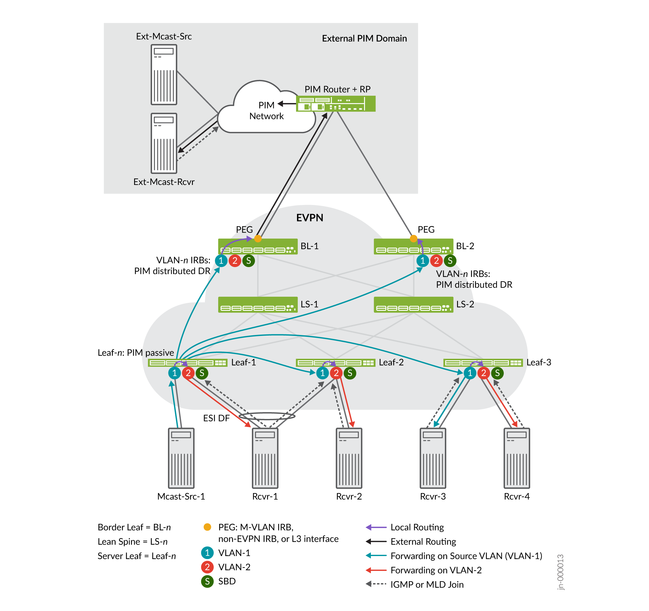
Figure 8 illustrates the OISM use case where a multicast source outside the EVPN fabric sends multicast traffic to receivers inside the fabric. In this case, the fabric uses the classic L3 interface or non-EVPN IRB external multicast method to connect to the external PIM domain. Also, this case includes the following internal receivers:
A receiver that is multihomed to two server leaf devices.
A local receiver on one of the border leaf devices.
This use case, like the M-VLAN IRB external source use case in Figure 7, shows the two main ways OISM uses the SBD in the EVPN core—To carry external multicast source traffic and to advertise SMET Type 6 routes. The Type 6 routes ensure that the border leaf devices only forward the traffic toward the EVPN devices with interested receivers.
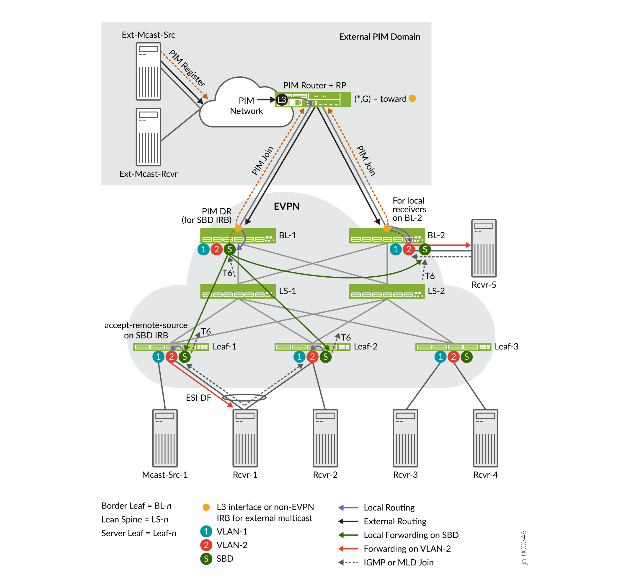
In Figure 8:
Rcvr-1 is multihomed to server leaf devices Leaf-1 and Leaf-2 in the EVPN fabric, and expresses interest in receiving traffic from a multicast group.
Rcvr-5 on BL-2 in the EVPN fabric is also interested in receiving the multicast traffic.
Ext-Mcast-Src in the external PIM domain is the source for the traffic for the multicast group.
The multicast control flow and data traffic flow for external multicast are similar for the classic L3 interface and the non-EVPN IRB interface methods. As a result, in this section we commonly say external multicast interface when we refer to the border leaf device external connection points.
The external source traffic reaches the interested receivers (Rcvr-1 and Rcvr-5) as follows:
- Multicast Control Flow between the Internal Receivers and the External Source—L3 Interface or Non-EVPN IRB Method
- Traffic Flow from the Border Leaf Devices to Internal Receivers—L3 Interface or Non-EVPN IRB Method
Multicast Control Flow between the Internal Receivers and the External Source—L3 Interface or Non-EVPN IRB Method
These steps summarize the multicast control flow in this use case:
Rcvr-1 sends an IGMP or MLD join message on VLAN-2 to both multihoming peers Leaf-1 and Leaf-2.
Both Leaf-1 and Leaf-2 generate an EVPN Type 6 route toward the EVPN core on the SBD. The Type 6 (SMET) route advertises that Rcvr-1 is interested in the multicast data.
Both border leaf devices BL-1 and BL-2 receive the Type 6 route on the SBD.
The Type 6 route (on the SBD) signals the border leaf devices to create a PIM join toward the PIM RP (reachable through the external multicast interface). However, to avoid duplicate join messages for server leaf devices on the SBD, only the border leaf device that is the PIM DR for the SBD generates the PIM join message. In this case, the figure shows the PIM DR for the SBD is BL-1. BL-1 sends the PIM join message toward the PIM RP by way of its PIM neighbor, the external multicast interface.
The local receiver on BL-2, Rcvr-5, also sends an IGMP or MLD join message on VLAN-2 to BL-2. Note that in this case, BL-1 and BL-2 are not multihoming peers in an EVPN ES. As a result, BL-2 sends a separate PIM join message on its external multicast interface because it has a local interested receiver (Rcvr-5).
The PIM RP receives the join messages. The PIM RP creates PIM (*,G) entries in the multicast routing table with the BL-1 and BL-2 external multicast interfaces as downstream interfaces.
The external source Ext-Mcast-Src registers with the PIM RP. The PIM RP has multicast routes for the group with the BL-1 and BL-2 external multicast interfaces as downstream interfaces. As a result, the PIM RP routes the multicast traffic coming in at L3 toward BL-1 and BL-2.
Both BL-1 and BL-2 receive the multicast traffic. The next section explains how the border leaf devices forward or route the traffic in the EVPN fabric.
Traffic Flow from the Border Leaf Devices to Internal Receivers—L3 Interface or Non-EVPN IRB Method
In Figure 8, BL-1 is the PIM DR for the SBD and sent the PIM join message toward the external PIM domain for server leaf devices on the SBD. BL-2 also sent a PIM join message toward the external PIM domain for its interested local receiver.
BL-1 and BL-2 receive the external source traffic, and route (or forward) it as follows:
BL-1 routes the traffic locally from the external multicast interface to the SBD IRB interface because BL-1 is the PIM DR for the SBD. See the small gray arrow from the external multicast interface to the SBD on BL-1.
BL-1 forwards a copy of the traffic on the SBD into the EVPN core to BL-2. See the green arrow from BL-1 toward BL-2.
However, BL-2 drops the traffic from the SBD because, as a PEG device using the classic L3 interface or non-EVPN IRB method, BL-2 doesn't expect external source traffic on the SBD IRB interface from BL-1. If BL-2 has interested receivers, it would have sent a PIM join message and should receive the same traffic from its external multicast connection.
Note:One reason why the ingress border leaf device also forwards a copy on the SBD to other border leaf devices is to ensure that another border leaf device can receive external source traffic if its external multicast interface is down. Then any interested local receivers on the other border leaf device can still get the traffic.
BL-2 routes the external multicast traffic to its local receiver, Rcvr-5, on VLAN-2. See the small gray arrow on BL-2 from the external multicast interface to VLAN-2.
Note:The border leaf devices configured in PEG mode that are not the PIM DR on the SBD will still locally route the traffic received from the external multicast interface. These devices don't send traffic from external multicast sources to other PEG border leaf devices on the SBD. These devices also don't forward the traffic on the SBD into the EVPN core.
BL-1 (the PIM DR on the SBD) selectively forwards copies of the traffic on the SBD to the server leaf devices with interested receivers (based on the advertised Type 6 routes). See the green arrows from BL-1 toward Leaf-1 and Leaf-2.
In this case, Leaf-1 and Leaf-2 have a multihomed interested receiver, Rcvr-1, on VLAN-2. As a result, BL-1 sends the traffic on the SBD toward both leaf devices.
Leaf-1 and Leaf-2 locally route the traffic from the SBD IRB interface to the revenue bridge domain IRB interface for VLAN-2 toward the interested (multihomed) receiver. However, with EVPN multihoming, only the EVPN DF in the ES forwards the traffic toward Rcvr-1 so Rcvr-1 doesn't get duplicate traffic.
In this case, Leaf-1 is the EVPN DF, so only Leaf-1 forwards the traffic to Rcvr-1. See the red arrow from Leaf-1 toward Rcvr-1.
AR and OISM with an Internal Multicast Source
In Figure 9, we show an OISM use case where you configure the spine devices as standalone AR replicator devices. The OISM server leaf and border leaf devices are AR leaf devices. The AR replicator devices handle replicating the multicast traffic for the OISM server leaf and border leaf devices. This case shows a multicast source and single-homed receivers behind server leaf devices inside the EVPN fabric.
AR behavior is different when the multicast source is behind a server leaf device that also has a multihomed receiver; see AR and OISM with an Internal Multicast Source and Multihomed Receiver for more on the behavior with that use case.
With OISM traffic from an internal source, the ingress device forwards the traffic in the EVPN fabric on the source VLAN. When you also enable AR, the ingress leaf device forwards one copy of the traffic to an AR replicator. The AR replicator replicates the traffic and sends the copies on the source VLAN to the other leaf devices with interested receivers. Then each leaf device:
Locally forwards the traffic toward its receivers on the source VLAN.
Locally routes the traffic toward its receivers on the other revenue VLANs.
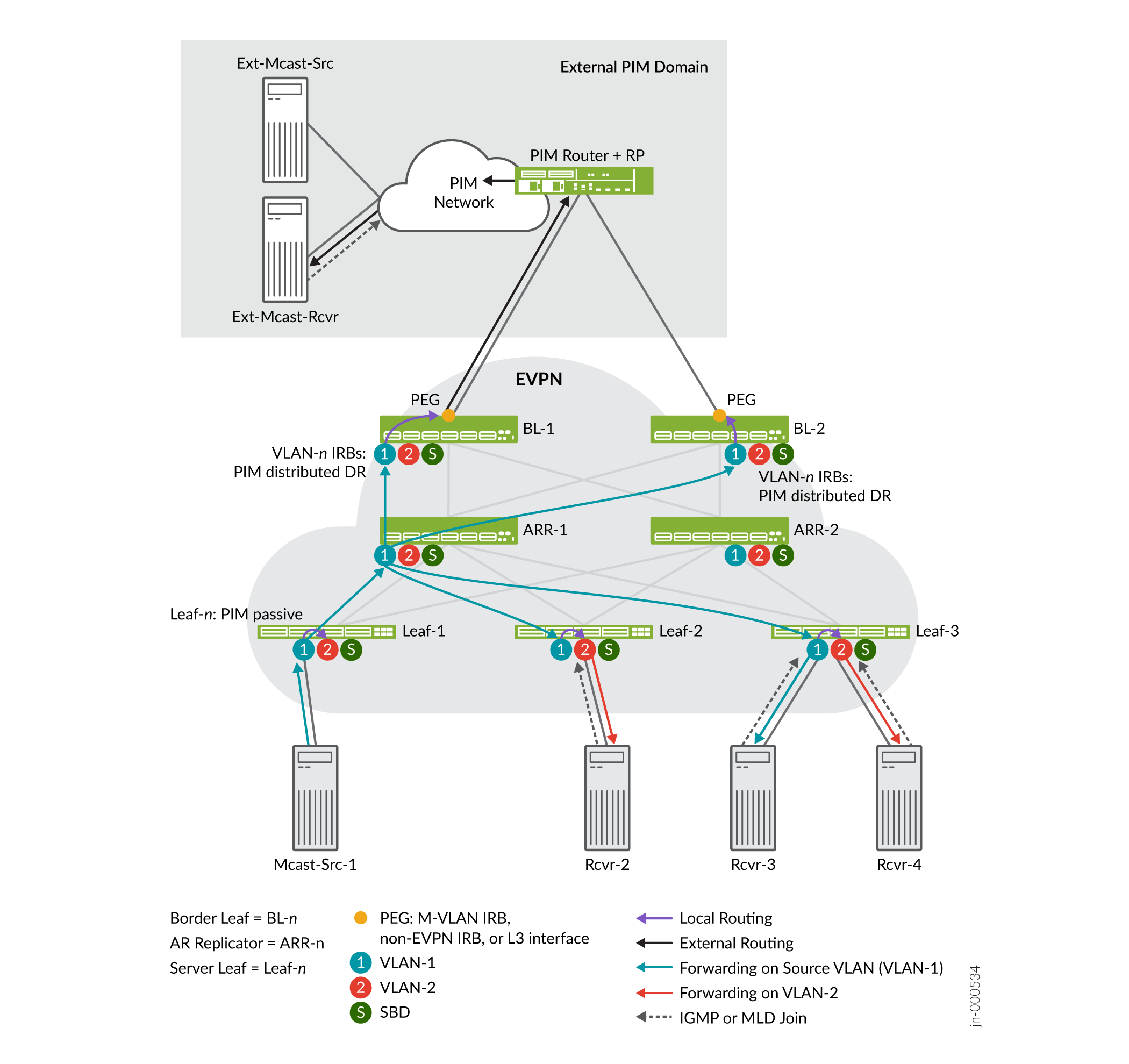
In the use case in Figure 9:
Rcvr-2, Rcvr-3 and Rcvr-4 send IGMP or MLD reports to join the multicast group.
The traffic source for the multicast group, Mcast-Src-1, forwards the traffic on the source VLAN, VLAN-1, to Leaf-1.
Leaf-1 forwards the traffic to one of the available AR replicators on VLAN-1 to replicate the traffic to the other leaf devices with interested receivers. In this case, Leaf-1 forwards the traffic to ARR-1.
Note:See AR Leaf Device Load Balancing with Multiple Replicators for details on how AR leaf devices load-balance among multiple available AR replicators.
ARR-1 replicates the traffic and sends copies on VLAN-1 toward all the leaf devices with interested receivers.
Each server leaf device:
Forwards the traffic toward the interested receivers on VLAN-1.
Locally routes the traffic to VLAN-2 and forwards it toward the interested receivers on VLAN-2.
Also note that in Figure 9, Rcvr-1 is multihomed to Leaf-1 and Leaf-2, with Leaf-1 as the ESI DF. As a result, only Leaf-1 forwards the traffic to Rcvr-1 on VLAN-2.
If any external receivers expressed interest in receiving the traffic, the border leaf devices locally route the traffic to the external multicast interface. The external multicast interface sends the traffic toward any interested external receivers based on the external multicast method you configure.
See Configure Assisted Replication for details on how to configure AR.
AR and OISM with an Internal Multicast Source and Multihomed Receiver
In Figure 10, we show an OISM use case similar to the setup in AR and OISM with an Internal Multicast Source. However, in this case, the multicast source is behind a server leaf device that also has a multihomed receiver. In this case, AR operates in extended AR mode by default to efficiently support the multihomed receiver. See Extended AR Mode for Multihomed Ethernet Segments for full details on this mode.
Here is a summary of how multicast traffic ingressing on a server leaf device reaches a multihomed receiver in this case:
The ingress server leaf device with an ESI for a multihomed receiver maintains a list of its multihoming peer leaf devices on the ES.
The AR replicator device also knows which AR leaf devices have multihoming peers.
The ingress server leaf device takes care of replicating and forwarding the multicast traffic to any of its multihoming peers that are interested in the traffic.
The ingress leaf device also sends one copy to an AR replicator device to handle replication and forwarding to any other leaf devices.
Other than this difference in handling replication to the multihoming peers, the traffic flow to an AR replicator and then to the interested receivers is the same as we describe in AR and OISM with an Internal Multicast Source.
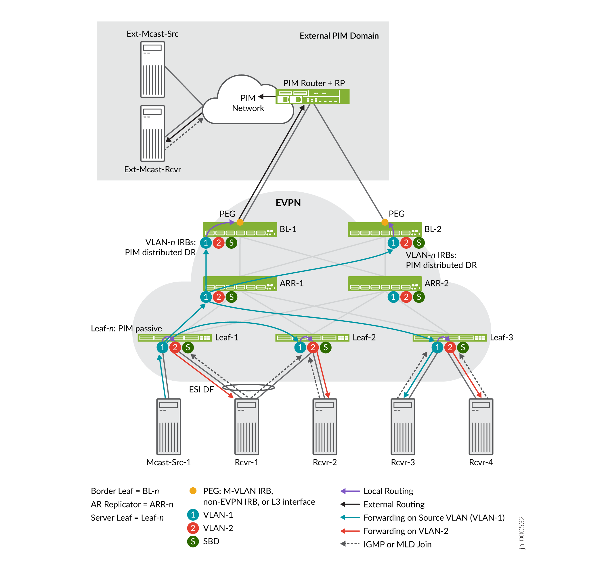
In Figure 10:
Rcvr-1, Rcvr-2, Rcvr-3 and Rcvr-4 send IGMP or MLD reports to join the multicast group.
The traffic source for the multicast group, Mcast-Src-1, forwards the traffic on the source VLAN, VLAN-1, to Leaf-1.
Following the extended AR mode for multihoming peers, Leaf-1 forwards the traffic directly to its multihoming peer Leaf-2, which has an interested receiver. Leaf-1 uses the source VLAN, VLAN-1, according to OISM behavior.
Leaf-1 also forwards the traffic to one of the available AR replicators, ARR-1 in this case, on the source VLAN, VLAN-1.
Note:See AR Leaf Device Load Balancing with Multiple Replicators for details on how AR leaf devices load-balance among multiple available AR replicators.
ARR-1 replicates the traffic and sends copies on VLAN-1 only toward the other leaf devices with interested receivers besides Leaf-2. Due to the default extended AR mode behavior (see Step 3 above), ARR-1 skips sending the traffic to Leaf-2, the multihoming peer of the ingress leaf device Leaf-1.
Each server leaf device then forwards or routes the traffic to its interested receivers.
Note that in Figure 10, Leaf-1 is the ESI DF for multihomed receiver Rcvr-2. As a result, only Leaf-1 forwards the traffic to Rcvr-1 on VLAN-2.
See Configure Assisted Replication for details on how to configure AR.
AR and OISM with an External Multicast Source
In Figure 11, we show an OISM use case where you configure the spine devices as standalone AR replicator devices. The OISM server leaf and border leaf devices are AR leaf devices. The multicast source is outside the EVPN fabric in an external PIM domain. The border leaf devices in this case use the classic L3 interface method to connect to the PIM router and PIM RP.
With OISM traffic from an external source, the ingress border leaf device forwards the traffic in the EVPN fabric on the SBD VLAN. When you also enable AR, the ingress border leaf device forwards one copy of the traffic to an AR replicator. The AR replicator replicates the traffic and sends the copies on the SBD VLAN to the other leaf devices with interested receivers. Then each device locally routes the traffic it receives on the SBD toward its receivers on the revenue bridge domain VLANs.
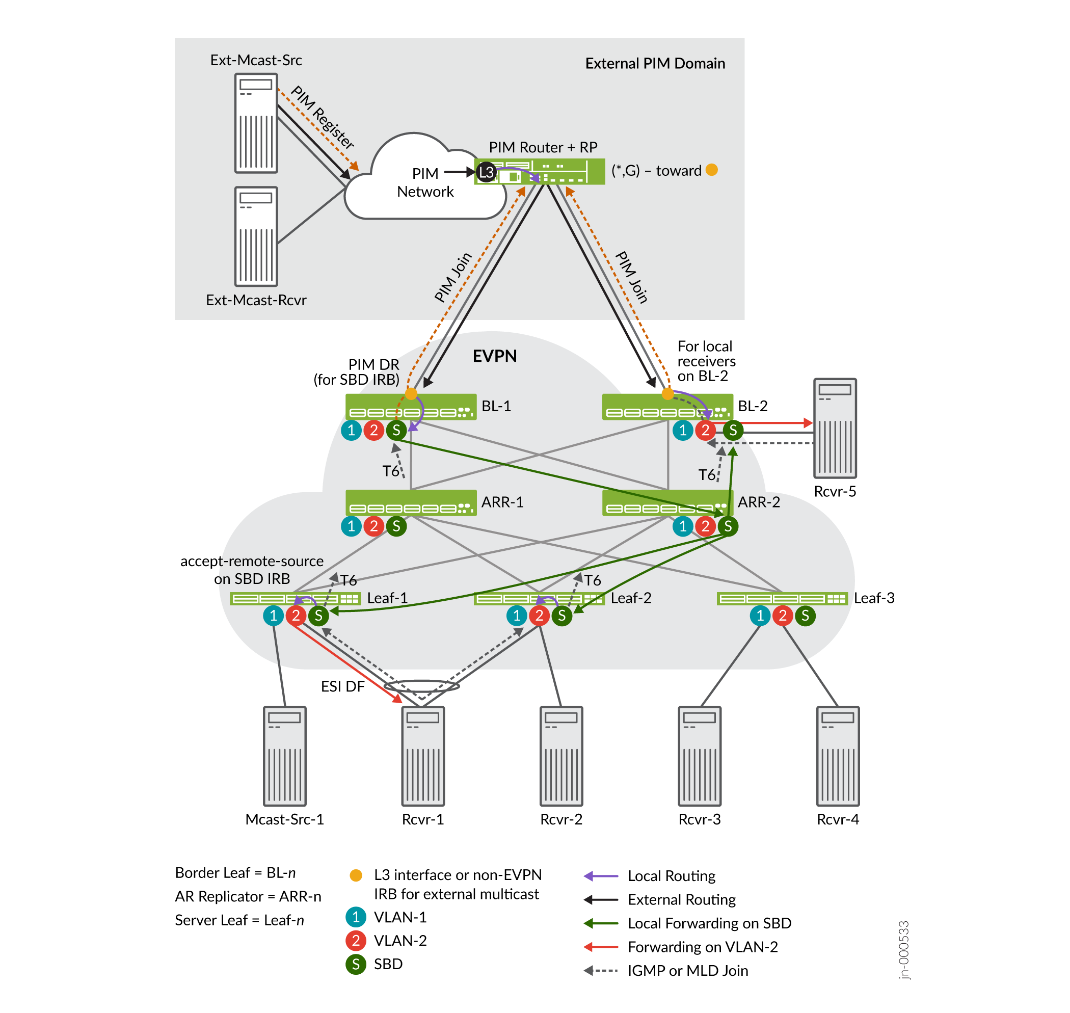
In the use case in Figure 11:
Rcvr-1 (multihomed to Leaf-1 and Leaf-2) and Rcvr-5 (a local host behind BL-2) send IGMP or MLD reports to join the multicast group.
The external source, Ext-Mcast-Src, sends multicast traffic through the external PIM domain. In this case we use the classic L3 interface external multicast method, and both devices sent a PIM join message, so the PIM router sends the traffic to both BL-1 and BL-2. (See Multicast Traffic from an External Source to Receivers Inside the EVPN Data Center—L3 Interface Method or Non-EVPN IRB Method for a full explanation of this behavior.)
Note:As Figure 11 shows, in this use case, because BL-2 has a local receiver, BL-2 routes the incoming externally sourced traffic directly toward its receiver on VLAN-2. BL-2 doesn't route traffic to the local receiver that it receives on the SBD from ARR-2 because its reverse-path forwarding toward the external source refers to the L3 interface.
BL-2 also doesn't route the traffic to the SBD because BL-1 is the PIM DR on the SBD (see the next step).
BL-1 is the PIM DR for the SBD, so BL-1 is the border leaf device that routes the externally sourced traffic into the EVPN fabric. With AR enabled, BL-1 forwards the traffic on the SBD to one of the available AR replicators. In this case, BL-1 forwards the traffic to ARR-2.
Note:See AR Leaf Device Load Balancing with Multiple Replicators for details on how AR leaf devices load-balance among multiple AR replicators.
ARR-2 replicates the traffic and sends copies on the SBD toward the leaf devices with interested receivers—in this case, Leaf-1, Leaf-2, and BL-2.
Each leaf device that receives the traffic on the SBD locally routes the traffic toward the interested receivers on the revenue VLANs. In this case:
BL-2 routes the traffic toward its receiver on VLAN-2.
Both Leaf 1 and Leaf-2 receive the traffic on the SBD. Rcvr-1 is multihomed to Leaf-1 and Leaf-2, and Leaf-1 is the ESI DF. As a result, only Leaf-1 forwards the traffic toward Rcvr-1 on VLAN-2.
See Configure Assisted Replication for details on how to configure AR.
How Enhanced OISM Works
The use cases we support with enhanced OISM (the asymmetric bridge domains model) are similar to those we describe in How OISM Works, but with a few operational differences. Also, as mentioned previously, you don't need to configure all VLANs on all leaf devices the way you do with regular OISM.
See Overview of Enhanced OISM for a brief introduction to enhanced OISM mode differences compared to regular OISM mode. This section describes the main operational differences in more detail.
- Local Routing and East-West Traffic Differences with Enhanced OISM
- PIM Registration with Enhanced OISM for Internal Sources Based on EVPN Type 10 S-PMSI A-D Routes
Local Routing and East-West Traffic Differences with Enhanced OISM
With enhanced OISM, the OISM leaf devices perform local routing the same way as we describe for regular OISM in Local Routing on OISM Devices. However, to send the traffic to other OISM leaf devices that are not its multihoming peers, an enhanced OISM ingress leaf device routes source traffic on the SBD instead of forwarding it on the source VLAN. The receiving leaf devices then locally route the traffic from the SBD to the destination VLAN.
For an ingress leaf device that has multihoming peers (other OISM leaf devices with which the device shares at least one Ethernet segment), in that case only, the device forwards east-west multicast source traffic on the source VLAN to the multihoming peers instead of using the SBD. Then the receiving leaf devices forward or locally route the traffic to the destination VLAN.
See Figure 12. We need to configure the SBD on all devices for OISM to work. We don't need to configure VLAN-1 and VLAN-2 on leaf devices that don't have receivers on those VLANs.
Routing east-west traffic mostly on the SBD supports the asymmetric bridge domains model—all leaf devices don't need to host all of the source VLANs in the network. You only need to configure the SBD in common on all of the OISM leaf devices. In the case of multihoming peers, however, you must configure the revenue VLANs symmetrically on the devices that are multihoming peers.
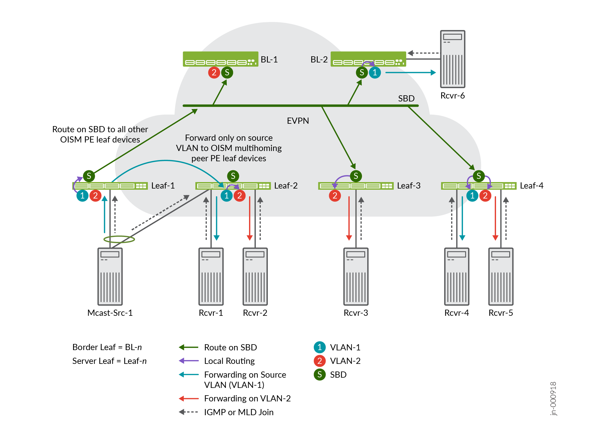
In Figure 12:
Receivers send IGMP or MLD join messages to express interest in receiving multicast traffic for a multicast group (*,G) or multicast source and group (S,G) on a particular VLAN.
Leaf-1 and Leaf-2 share an Ethernet segment for multihomed host Mcast-Src-1. As a result, we configure the same VLANs, VLAN-1 and VLAN-2, symmetrically on both of those devices, even though Leaf-1 might not have any receivers that use VLAN-2.
Leaf-1 receives the multicast traffic on the source VLAN, VLAN-1, and:
Forwards the traffic to Leaf-2, its multihoming peer, on the source VLAN, VLAN-2
Leaf-2 then forwards the traffic to interested receivers on the source VLAN, VLAN-1, or locally routes the traffic to interested receivers on destination VLAN VLAN-2.
Routes the traffic onto the SBD to the other OISM leaf devices that are not its multihoming peers and have interested receivers.
The OISM leaf devices receive the traffic on the SBD, and locally route the traffic to interested receivers on the destination VLAN, VLAN-1 or VLAN-2.
PIM Registration with Enhanced OISM for Internal Sources Based on EVPN Type 10 S-PMSI A-D Routes
Enhanced OISM requires some differences in handling PIM source registration for north-south traffic from internal sources to receivers outside of the EVPN network.
With regular OISM, the border leaf devices running as OISM PEG devices receive traffic from external multicast sources only on the supplemental bridge domain (SBD). The PEG devices receive traffic from internal multicast sources on the source VLAN. OISM PEG devices should only perform PIM registration for internal sources, so with the regular OISM design, the PEG devices can easily distinguish the internal sources, and do PIM source registration only for those sources.
With enhanced OISM, the PEG devices receive traffic on the SBD from both external and internal multicast sources. Because the PEG devices should only perform PIM registration to the PIM RP for internal sources, the PEG devices running enhanced OISM must be able to distinguish between internal and external multicast sources.
The enhanced OISM design employs EVPN Type 10 Selective P-router Multicast Service Interface (S-PMSI) Auto-Discovery (A-D) routes to make this distinction, as follows (and see Figure 13):
The ingress OISM leaf devices that receive traffic from internal multicast sources advertise S-PMSI A-D routes for those multicast (S,G) sources and groups.
If a PEG device receives traffic on an SBD IRB interface and doesn't see an S-PMSI A-D route for that source, the device interprets that source as an external source.
The PEG device only sends a PIM register to the PIM RP for the sources that correspond to received S-PMSI A-D routes.
This design ensures that the PEG devices perform PIM source registration only for the multicast sources inside the EVPN network.
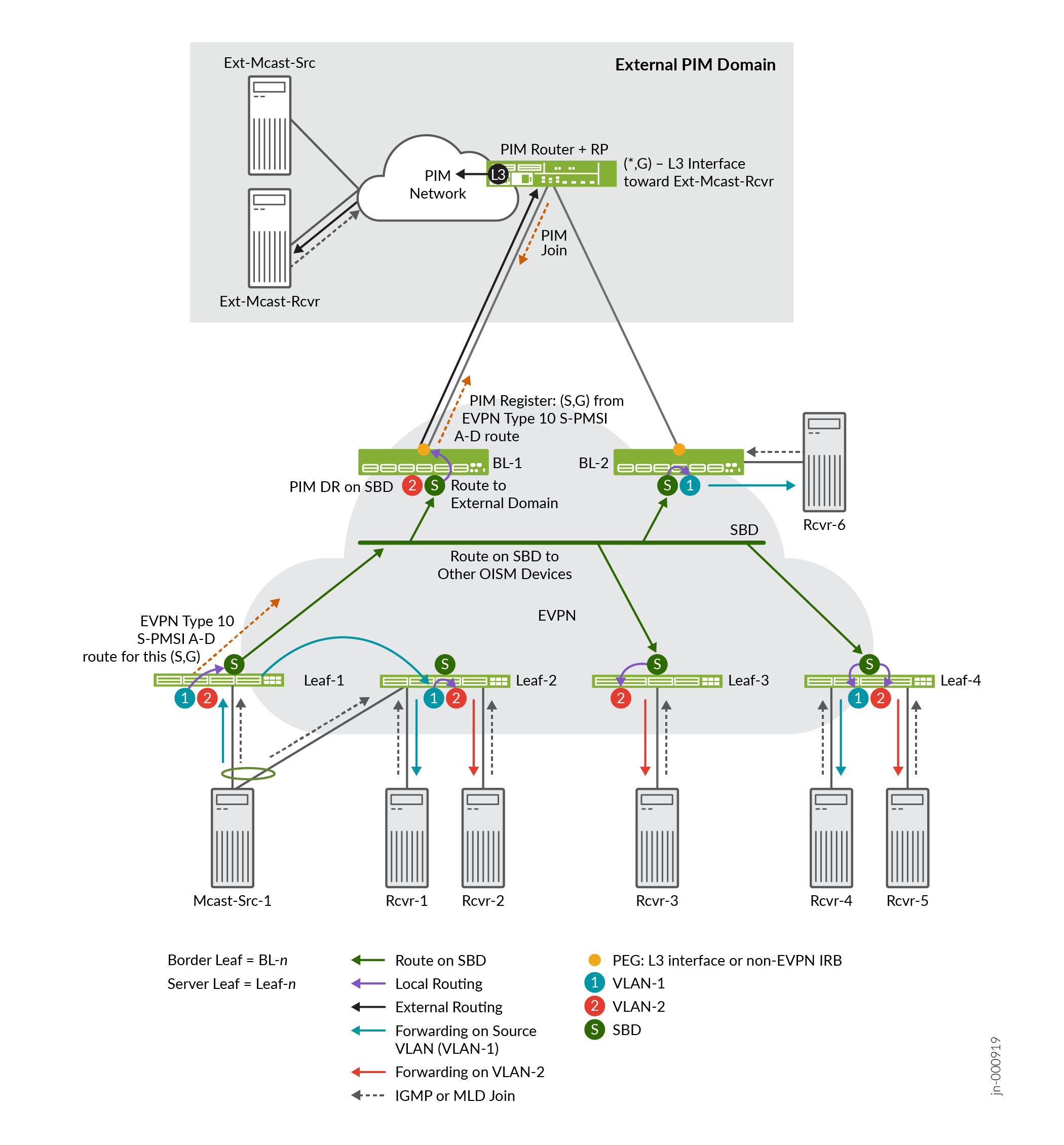
For example, Figure 13 shows the same enhanced OISM internal traffic flow as Figure 12 with the addition of the external PIM domain serving external receivers. In the figure:
When Leaf-1 receives multicast traffic from Mcast-Src-1, Leaf-1 generates an S-PMSI A-D route and sends it into the EVPN network.
PEG device BL-1 receives the S-PMSI A-D route. BL-2 also receives the S-PMSI A-D route. However, BL-1 is the PIM DR on the SBD, so BL-1 sends the PIM Register message on its external multicast interface toward the PIM RP for that (S,G).
The PIM RP sends a PIM Join message back toward BL-1. BL-1 receives the PIM join and creates an (S,G) multicast routing table entry for the external receiver.
When BL-1 receives multicast traffic for that (S,G) on the SBD, it locally routes the traffic to the external multicast interface toward the external receivers.
You can use commands such as the following to see details on the EVPN Type 10 S-PMSI A-D routes on the OISM leaf devices:
show evpn oism spmsi-ad extensive
show route table evpn-instance-name.evpn-mcsn.1 match 10* extensive
Considerations for OISM Configurations
Before you begin to set up your OISM installation, here are a few considerations in specific use cases. These considerations apply to both regular OISM and enhanced OISM modes unless the section specifies otherwise.
- IGMPv2 and IGMPv3 (or MLDv1 and MLDv2) in the Same EVPN-VXLAN Fabric
- Latency and Scaling Trade-Offs for Installing Multicast Routes with OISM (install-star-g-routes Option)
- OISM and AR Scaling with Many VLANs
- PEG DF Election
- Statically Identify Multihoming Peers With Enhanced OISM To Improve Convergence
- Enhanced OISM with an EVPN-VXLAN IPv6 Underlay Configuration
- Enhanced OISM Exception Policy to Forward on Source VLAN Instead of SBD for Packets with TTL=1
IGMPv2 and IGMPv3 (or MLDv1 and MLDv2) in the Same EVPN-VXLAN Fabric
You have several options to configure IGMP snooping with IGMPv2, IGMPv3, or both IGMP versions together in an EVPN-VXLAN fabric with OISM. The same is true of MLD snooping with MLDv1, MLDv2, or both MLD versions together. You might also want to mix configuring IGMP and MLD together in the same fabric. This section includes configuration considerations for a few of these options.
If you have traffic for either IGMPv2 or IGMPv3 on a device with OISM enabled, you can enable that IGMP version globally on the device with IGMP snooping. You can alternatively enable that IGMP version only for the interfaces that will handle the multicast traffic. You can enable IGMP snooping with that version of IGMP on all VLANs or on specific VLANs, as needed.
You have the same options for either MDLv1 or MLDv2 with MLD snooping (on the platforms that support MLD with OISM).
You can also enable one version of IGMP with IGMP snooping and one version of MLD with MLD snooping together on the device with OISM.
However, OISM supports IGMP snooping with both IGMPv2 and IGMPv3 traffic together on a device only within the following constraints:
You can't enable IGMP snooping with both IGMPv2 and IGMPv3 for interfaces in the same VLAN.
You can't enable IGMP snooping with both IGMPv2 and IGMPv3 for VLANs that are part of the same L3 VRF instance with OISM enabled.
The constraints above also apply if you want to enable MLD snooping with both MLDv1 and MLDv2 traffic together on a device.
These constraints don't apply if you use one version of IGMP with one version of MLD together on a device.
To support IGMP snooping with both IGMP versions, or MLD snooping with both MLD versions, you must configure:
One tenant VRF instance to support the IGMPv2 or MLDv1 receivers.
Another tenant VRF instance to support the IGMPv3 or MLDv2 receivers.
as follows:
In your configuration, define VLANs for the IGMPv2 receivers, and define different VLANs for the IGMPv3 receivers.
Similarly, for MLD, define VLANs for the MLDv1 receivers, and define different VLANs for the MLDv2 receivers.
Include the IRB interfaces that support IGMPv2 in one VRF instance, and enable IGMPv2 on those IRB interfaces. Enable IGMP snooping on the corresponding VLANs.
Similarly, for MLD, include the IRB interfaces that support MLDv1 in one VRF instance, and enable MLDv1 on those IRB interfaces. Enable MLD snooping on the corresponding VLANs.
Include the IRB interfaces that support IGMPv3 in another VRF instance, and enable IGMPv3 on those IRB interfaces. Enable IGMP snooping with the
evpn-ssm-reports-onlyoption on the corresponding VLANs.Similarly, for MLD, include the IRB interfaces that support MLDv2 in another VRF instance, and enable MLDv2 on those IRB interfaces. Enable MLD snooping with the
evpn-ssm-reports-onlyoption on the corresponding VLANs.
In this use case, for each IGMP or MLD version, allocate a set of VLANs and IRB interfaces for:
The OISM revenue bridge domains.
The SBD.
Any external multicast VLANs and interfaces (depending on the external multicast method you use).
You also define two L3 VRF instances for each tenant instance you need in your installation, one for each IGMP version or MLD version. If you use MAC-VRF routing instances at L2, you might want to allocate different MAC-VRF EVPN instances for the IGMP snooping or MLD snooping traffic for each IGMP or MLD version.
The next sections show example configurations with both versions of IGMP or both versions of MLD together. You can scale these simple scenarios to support different tenants with different combinations of IGMP or MLD versions.
See Supported IGMP or MLD Versions and Group Membership Report Modes for more information on IGMP any-source multicast (ASM) mode and source-specific multicast (SSM) mode support with IGMPv2, IGMPv3, MLDv1, and MLDv2 in EVPN-VXLAN fabrics.
- Example Configuration with IGMPv2 and IGMPv3 Together
- Example Configuration with MLDv1 and MLDv2 Together
Example Configuration with IGMPv2 and IGMPv3 Together
Consider a use case with both IGMP versions in a fabric you set up with the M-VLAN IRB method for external multicast. You want to support IGMP snooping with both IGMPv2 and IGMPv3 traffic. In that case, you might configure the following MAC-VRF instances, L3 VRF instances, VLANs, and corresponding IRB interfaces:
MAC-VRF2 and L3VRF-A to support IGMPv2 receivers:
Revenue bridge domain VLAN-100 with irb.100
SBD VLAN-302 with irb.302
(Border leaf devices only) M-VLAN VLAN-902 with irb.902
MAC-VRF3 and L3VRF-B to support IGMPv3 receivers:
Revenue bridge domain VLAN-200 with irb.200
SBD VLAN-303 with irb.303
(Border leaf devices only) M-VLAN VLAN-903 with irb.903
Then include the IGMPv2 IRB interfaces in L3VRF-A and enable IGMPv2 for those IRB interfaces. Include the IGMPv3 IRB interfaces in L3VRF-B and enable IGMPv3 for those IRB interfaces.
For example:
set routing-instances L3VRF-A interface irb.100 # revenue bridge domain for IGMPv2 receivers set routing-instances L3VRF-A interface irb.302 # SBD for IGMPv2 receivers set routing-instances L3VRF-A interface irb.902 # M-VLAN for IGMPv2 (border leaf only) set routing-instances L3VRF-B interface irb.200 # revenue bridge domain for IGMPv3 receivers set routing-instances L3VRF-B interface irb.303 # SBD for IGMPv3 receivers set routing-instances L3VRF-B interface irb.903 # M-VLAN for IGMPv3 (border leaf only) # version 2 option isn't required for IGMPv2 because that's the default IGMP version set protocols igmp interface irb.100 <version 2> # revenue bridge domain for IGMPv2 receivers set protocols igmp interface irb.302 <version 2> # SBD for IGMPv2 receivers set protocols igmp interface irb.902 <version 2> # M-VLAN for IGMPv2 (border leaf only) # version 3 option is required to enable IGMPv3 set protocols igmp interface irb.200 version 3 # revenue bridge domain for IGMPv3 receivers set protocols igmp interface irb.303 version 3 # SBD for IGMPv3 receivers set protocols igmp interface irb.903 version 3 # M-VLAN for IGMPv3 (border leaf only)
Finally, enable IGMP snooping at L2 in the EVPN instances as follows:
Configure
igmp-snoopingin MAC-VRF2 for the VLANs corresponding to the IGMPv2 IRB interfaces.Configure
igmp-snoopingin MAC-VRF3 for the VLANs corresponding to the IGMPv3 IRB interfaces.Include the
evpn-ssm-reports-onlyoption only when you enable IGMP snooping for IGMPv3 traffic.
For example:
set routing-instances MAC-VRF2 protocols igmp-snooping vlan VLAN-100 # IGMPv2-enabled VLAN set routing-instances MAC-VRF2 protocols igmp-snooping vlan VLAN-302 # IGMPv2-enabled VLAN set routing-instances MAC-VRF2 protocols igmp-snooping vlan VLAN-902 # IGMPv2-enabled VLAN set routing-instances MAC-VRF3 protocols igmp-snooping vlan VLAN-200 evpn-ssm-reports-only # IGMPv3-enabled VLAN set routing-instances MAC-VRF3 protocols igmp-snooping vlan VLAN-303 evpn-ssm-reports-only # IGMPv3-enabled VLAN set routing-instances MAC-VRF3 protocols igmp-snooping vlan VLAN-903 evpn-ssm-reports-only # IGMPv3-enabled VLAN
With the non-EVPN IRB method for external multicast, you don't include the evpn-ssm-reports-only option on the non-EVPN IRB interface. You don't need this option because with the non-EVPN IRB method, you don't extend the external multicast interface in the EVPN instance.
When you use the L3 interface method for external multicast, you don't enable IGMP snooping at all on the L3 interface to the external PIM domain. That interface operates at L3, while IGMP snooping operates at L2.
Example Configuration with MLDv1 and MLDv2 Together
Consider this use case with both MLDv1 and MLDv2 with MLD snooping in a fabric with OISM:
MAC-VRF1 and L3VRF-A to support MLDv1 receivers:
Revenue bridge domain VLAN-100 with irb.100
SBD VLAN-301 with irb.301
MAC-VRF2 and L3VRF-B to support MLDv2 receivers:
Revenue bridge domain VLAN-200 with irb.200
SBD VLAN-302 with irb.302
In this use case, we don't use the M-VLAN IRB method for external multicast, so we don't configure an M-VLAN IRB interface like we do in the IGMP use case above.
In this case, you configure:
MLDv1 on the IRB interfaces for MLDv1 receivers (VLANs 100 and 301).
MLDV2 on the IRB interfaces for MLDv2 receivers (VLANs 200 and 302)
MLD snooping for MLDv1 VLANs in MAC-VRF1.
MLD snooping for MLDv2 VLANs with the
evpn-ssm-reports-onlyoption in MAC-VRF2.
For example:
set routing-instances L3VRF-A interface irb.100 # revenue bridge domain for MLDv1 receivers set routing-instances L3VRF-A interface irb.301 # SBD for MLDv1 receivers set routing-instances L3VRF-B interface irb.200 # revenue bridge domain for MLDv2 receivers set routing-instances L3VRF-B interface irb.302 # SBD for MLDv2 receivers # version 1 option isn't required for MLDv1 because that's the default MLD version set protocols mld interface irb.100 # revenue bridge domain for MLDv1 receivers set protocols mld interface irb.301 # SBD for MLDv1 receivers set protocols mld interface irb.200 version 2 # revenue bridge domain for MLDv2 receivers set protocols mld interface irb.302 version 2 # SBD for MLDv2 receivers set routing-instances MAC-VRF1 protocols mld-snooping vlan VLAN-100 # MLDv1-enabled VLAN set routing-instances MAC-VRF1 protocols mld-snooping vlan VLAN-301 # MLDv1-enabled VLAN set routing-instances MAC-VRF2 protocols mld-snooping vlan VLAN-200 evpn-ssm-reports-only # MLDv2-enabled VLAN set routing-instances MAC-VRF2 protocols mld-snooping vlan VLAN-302 evpn-ssm-reports-only # MLDv2-enabled VLAN
Latency and Scaling Trade-Offs for Installing Multicast Routes with OISM (install-star-g-routes Option)
Devices in an OISM-enabled fabric send EVPN Type 6 routes so other EVPN devices learn about receivers that are interested in the traffic for a multicast group. The receivers are in different OISM revenue bridge domains in an L3 VRF instance. To save bandwidth in the EVPN fabric core, OISM devices send and receive the Type 6 routes only on the OISM SBD in the routing instance.
To help minimizes packet loss at the onset of a multicast flow, we provide the install-star-g-routes option at the [edit <routing-instances name> multicast-snooping-options oism] hierarchy level (see oism (Multicast Snooping Options)). When you configure this option, upon receiving a Type 6 route, the RE on the device immediately installs corresponding (*,G) multicast routes on the PFE for all of the revenue bridge domain VLANs in the routing instance.
With this option, you trade off taking up extra PFE resources to improve network latency. Lower-scale deployments might have fewer multicast flows but have strict network latency requirements. To improve network latency in that case, the device installs the (*,G) routes in the data plane in advance of any incoming multicast traffic.
Configure this option:
Globally if you configure EVPN in the default-switch instance, at the
[edit multicast-snooping-options oism]hierarchy level.In the MAC-VRF instances if you configure EVPN in instances of type
mac-vrf, at the[edit routing-instances instance-name multicast-snooping-options oism].
We require that you configure install-star-g-routes with OISM on the QFX10000
line of switches, QFX5130 switches, and QFX5700 switches when you
configure those devices with AR in the AR replicator role.
In releases prior to Junos OS and Junos OS Evolved Release 23.4R1, you must also configure the install-star-g-routes option on the following devices when you configure them as OISM server leaf or border leaf devices:
Switches in the QFX10000 line.
PTX10001-36MR, PTX10004, PTX10008, and PTX10016 routers.
Starting in Junos OS and Junos OS Evolved Release 23.4R1, we no longer require you to set this option when you configure those devices as OISM server leaf or border leaf devices.
We don't recommend setting this option other than in the use cases mentioned above.
Consider this option only if you have very stringent latency requirements and can trade off higher scaling to achieve better network latency.
The functions of the install-star-g-routes option and the conserve-mcast-routes-in-pfe option are mutually exclusive, so you can use only one or the other of these options in a routing instance. See ACX Series Routers, QFX5130 Switches, and QFX5700 Switches as Server Leaf and
Border Leaf Devices with OISM for more on when to use the conserve-mcast-routes-in-pfe option.
- Default Behavior without the install-star-g-routes Option
- Behavior with the install-star-g-routes Option
Default Behavior without the install-star-g-routes Option
By default, without this option, the device prioritizes saving resources on the PFE by not installing multicast routes until the multicast traffic arrives. In this default case:
The PFE receives multicast traffic from source S for multicast group G.
The PFE doesn't have forwarding next-hop information for the traffic, so it signals the RE to get that information.
Note:The PFE drops multicast traffic until it gets the routing information.
The RE learns about the multicast flow for (S,G) from the PFE, and installs that route on the PFE.
The PFE sends the traffic on the next hop in the installed (S,G) route.
Behavior with the install-star-g-routes Option
With the install-star-g-routes option, the device prioritizes having multicast routing information available on the PFE before any traffic arrives. The device consumes extra PFE resources for routes that it isn't using yet (and might never be used). With this option:
The RE receives an EVPN Type 6 route for a receiver subscribing to traffic for a multicast group G on the OISM SBD in a routing instance.
The RE installs corresponding (*,G) routes on the PFE for all of the revenue bridge domains in the L3 VRF instance.
At some later time, the PFE receives multicast traffic from source S for multicast group G.
The PFE has forwarding next hop information for traffic for (*,G). So it forwards the traffic to receivers on any revenue bridge domains using the (*,G) route next hop.
The PFE also signals the RE that it has received multicast traffic from source S for multicast group G.
The RE learns about the multicast flow for (S,G) from the PFE. The RE installs the (S,G) route on the PFE.
The PFE continues sending the traffic, but now uses the (S,G) route and the next hop in that more specific route.
Note:The PFE still retains the (*,G) routes per revenue bridge domain that the RE installed after receiving the Type 6 route.
OISM and AR Scaling with Many VLANs
With OISM and IGMP snooping or MLD snooping enabled in an EVPN-VXLAN fabric, OISM server leaf and border leaf devices send EVPN Type 6 SMET routes into the EVPN core when their receivers join a multicast group.
When an OISM-enabled device receives Type 6 routes on the SBD, the device:
Derives multicast states from the Type 6 routes as follows:
(*,G) states for IGMPv2 or MLDv1
(S,G) states for IGMPv3 or MLDv2
Installs the derived states on the OISM SBD and revenue bridge domain VLANs in the MAC-VRF instance for all VLANs that are part of OISM-enabled L3 tenant VRF instances.
Uses the derived multicast routes to optimize multicast forwarding by selectively sending the traffic for a group only to other EVPN devices that have receivers subscribed to that group.
On some devices that support OISM, you can also configure the assisted replication (AR) multicast optimization feature with OISM enabled. AR replicator devices use the Type 6 routes the same way OISM devices do.
QFX5130 and QFX5700 switches can serve as OISM server leaf or border leaf devices. They can act as AR replicators only on devices that are not also OISM server leaf or border leaf devices. In that case, the device operates in the standalone AR replicator role.
The next sections describe configuration considerations on these devices when you configure them as OISM server leaf or border leaf devices, or as standalone AR replicators with OISM.
The use cases and sample configurations in the next sections show IGMP configurations for IPv4 multicast, but also apply in the same ways to MLD configurations for IPv6 multicast.
- ACX Series Routers, QFX5130 Switches, and QFX5700 Switches as Server Leaf and Border Leaf Devices with OISM
- QFX5130 and QFX5700 Switches as Standalone AR Replicators with OISM
ACX Series Routers, QFX5130 Switches, and QFX5700 Switches as Server Leaf and Border Leaf Devices with OISM
When you configure ACX Series routers, QFX5130 switches, and QFX5700 switches as server leaf or border leaf devices with OISM, as soon as these devices receive multicast traffic, they use the L3 multicast routes from PIM to forward the traffic. They use the derived multicast snooping states only to learn which receivers are interested in a multicast stream. They don't need to save the multicast snooping derived states in the forwarding plane for forwarding traffic.
Starting in Junos OS Evolved Releases 22.4R2 and 23.1R1, when you configure these devices as OISM server leaf and border leaf devices, we require you to also configure the conserve-mcast-routes-in-pfe option at the [edit routing-instances name multicast-snooping-options oism] hierarchy level. (See oism (Multicast Snooping Options).) With this option, these devices conserve PFE table space by installing only the L3 multicast routes; they avoid installing L2 multicast snooping routes.
Use the following guidelines for setting the conserve-mcast-routes-in-pfe option:
You must set this option on ACX Series routers, QFX5130 switches, and QFX5700 switches when you configure them as server leaf or border leaf devices with OISM enabled.
Set this option in all OISM-enabled MAC-VRF EVPN routing instances on the device.
Don't configure this option if you did not enable OISM on the device.
When you disable OISM on a device, you must also delete this setting.
The functions of the conserve-mcast-routes-in-pfe option and the install-star-g-routes option are mutually exclusive, so you can use only one or the other of these options in a routing instance. See Latency and Scaling Trade-Offs for Installing Multicast Routes with OISM (install-star-g-routes Option) for more on when to use the install-star-g-routes option.
QFX5130 and QFX5700 Switches as Standalone AR Replicators with OISM
QFX5130 and QFX5700 switches can serve as standalone AR replicators in a fabric with OISM. However, in fabrics with many VLANs, QFX5130 and QFX5700 switches might have scaling issues when installing the multicast states on all the OISM VLANs.
As a result, starting in Junos OS Evolved 22.2R1, when you configure these switches as standalone AR replicators with OISM enabled, by default these switches only install multicast states on the SBD VLAN. (This includes multicast (*,G) states for IGMPv2 and multicast (S,G) states for IGMPv3.) These switches don’t install the multicast states on all the revenue bridge domain VLANs.
For example, consider a QFX5130 device where you have a MAC-VRF instance evpn-vxlan-A
with 3 VLANs—VLAN_2, VLAN_3, and VLAN_4. The show igmp snooping evpn
status detail command shows that you configured VLAN_4 as the
SBD (the Supplementary BD output field is
Yes), and the other two VLANs are OISM revenue bridge
domain VLANs:
user@device> show igmp snooping evpn status detail
Instance: evpn-vxlan-A
Bridge-Domain: VLAN_2, VN Identifier: 2
OISM : Enabled
Supplementary BD: No
External VLAN : No
Bridge-Domain: VLAN_3, VN Identifier: 3
OISM : Enabled
Supplementary BD: No
External VLAN : No
Bridge-Domain: VLAN_4, VN Identifier: 4
OISM : Enabled
Supplementary BD: Yes
External VLAN : No
The device received Type 6 routes from remote devices for multicast groups 233.252.0.1 and 233.252.0.2:
user@device> show route table bgp.evpn.0 match-prefix 6*233.252.0.1*
bgp.evpn.0: 269 destinations, 269 routes (269 active, 0 holddown, 0 hidden)
+ = Active Route, - = Last Active, * = Both
6:192.168.0.1:9::4::233.252.0.1::192.168.0.1/520
*[BGP/170] 00:10:28, localpref 100, from 192.168.0.1
AS path: I, validation-state: unverified
> to 10.1.1.2 via et-0/0/3:0.0
6: 192.168.0.2:9::4::233.252.0.1:: 192.168.0.2/520
*[BGP/170] 00:09:30, localpref 100, from 192.168.0.2
AS path: I, validation-state: unverified
> to 10.1.2.2 via et-0/0/3:2.0
6: 192.168.0.3:9::4::233.252.0.1::192.168.0.3/520
*[BGP/170] 00:12:14, localpref 100, from 192.168.0.3
AS path: I, validation-state: unverified
> to 10.1.3.2 via ae1.0
user@device> show route table bgp.evpn.0 match-prefix 6*233.252.0.2*
bgp.evpn.0: 269 destinations, 269 routes (269 active, 0 holddown, 0 hidden)
+ = Active Route, - = Last Active, * = Both
6:192.168.0.1:9::4::233.252.0.2::192.168.0.1/520
*[BGP/170] 00:10:34, localpref 100, from 192.168.0.1
AS path: I, validation-state: unverified
> to 10.1.1.2 via et-0/0/3:0.0
6: 192.168.0.2:9::4::233.252.0.2:: 192.168.0.2/520
*[BGP/170] 00:09:36, localpref 100, from 192.168.0.2
AS path: I, validation-state: unverified
> to 10.1.2.2 via et-0/0/3:2.0
6: 192.168.0.3:9::4::233.252.0.2:: 192.168.0.3/520
*[BGP/170] 00:12:20, localpref 100, from 192.168.0.3
AS path: I, validation-state: unverified
> to 10.1.3.2 via ae1.0Due to the scaling behavior difference on QFX5130 or QFX5700 switches, if you run the
show multicast snooping route command on these devices,
the output shows multicast group entries only on the SBD, and not on any of
the revenue bridge domains. For example, with our multicast groups
233.252.0.1 and 233.252.0.2:
user@device> show multicast snooping route extensive instance evpn-vxlan-A
Nexthop Bulking: OFF
Family: INET
Group: 224.0.0.0/4
Source: *
Vlan: VLAN_2
Mesh-group: __ar_flood__
Downstream interface list:
evpn-core-nh -(639026)
Statistics: 0 kBps, 0 pps, 0 packets
Next-hop ID: 639104
Route state: Active
Forwarding state: Forwarding
Sensor ID: 4026531845
Group: 224.0.0.0/4
Source: *
Vlan: VLAN_3
Mesh-group: __ar_flood__
Downstream interface list:
evpn-core-nh -(639022)
Statistics: 0 kBps, 0 pps, 0 packets
Next-hop ID: 639106
Route state: Active
Forwarding state: Forwarding
Sensor ID: 4026531846
Group: 224.0.0.0/4
Source: *
Vlan: VLAN_4
Mesh-group: __ar_flood__
Downstream interface list:
evpn-core-nh -(639018)
Statistics: 0 kBps, 0 pps, 0 packets
Next-hop ID: 639097
Route state: Active
Forwarding state: Forwarding
Sensor ID: 4026531844
Group: 233.252.0.1/32
Source: *
Vlan: VLAN_4
Mesh-group: __ar_flood__
Downstream interface list:
evpn-core-nh -(165537)
Statistics: 523 kBps, 500 pps, 290630 packets
Next-hop ID: 220045
Route state: Active
Forwarding state: Forwarding
Sensor ID: 4026531843
Group: 233.252.0.2/32
Source: *
Vlan: VLAN_4
Mesh-group: __ar_flood__
Downstream interface list:
evpn-core-nh -(165537)
Statistics: 0 kBps, 0 pps, 238 packets
Next-hop ID: 220045
Route state: Active
Forwarding state: Forwarding
Sensor ID: 4026531842QFX5130 or QFX5700 switches that are not running as AR replicators with OISM will
install the multicast group entries on the revenue bridge
domain VLANs and the SBD. When you run the show multicast snooping
route command in that case, you see the revenue
bridge domain VLANs and the SBD . This behavior also applies to all other
platforms running OISM whether the device is an AR replicator or not.
On QFX5130 or QFX5700 switches acting as AR replicators, you should not configure the
conserve-mcast-routes-in-pfe option we describe in
ACX Series Routers, QFX5130 Switches, and QFX5700 Switches as Server Leaf and
Border Leaf Devices with OISM.
PEG DF Election
By default, peer OISM PEG devices use PIM-based DF election—the devices discover their PIM neighbors on the OISM revenue VLANs and the SBD in each L3 VRF, and elect the DF from among those neighbors. Starting in Junos OS Release 23.4R1 and Junos OS Evolved Release 23.4R1, you can instead configure mod-based or preference-based PEG DF election using the peg-df-election statement at the [edit routing-instances name protocols evpn oism pim-evpn-gateway] hierarchy level, as follows:
peg-df-election {
delay-time num;
mod; # default method if you don't configure either the mod or preference option
preference {
use-least;
value preference-value;
};
}When you configure PEG DF election, the device maintains an ordinal list of the PEG devices in the fabric that host each revenue VLAN (bridge domain) or the SBD. PEG devices use the EVPN multicast flags extended community in EVPN Type 3 IMET routes to advertise OISM, IGMP snooping, MLD snooping, and PEG device support. In addition, PEG devices include the DF election extended community to communicate the configured DF election method parameters (as defined in the RFC 8584 standard).
The peer PEG DF candidates are the devices that advertise IMET routes for a revenue VLAN or the SBD with the following EVPN multicast flags extended community values:
- For IPv4 multicast—igmp-snooping-enabled:oism:peg
- For IPv6 multicast—mld-snooping-enabled:oism:pegNote:
The devices elect a DF for IPv4 multicast traffic and a DF for IPv6 multicast traffic separately based on those advertised multicast flags extended community values.
When the PEG devices use PEG DF election, they don't use the PIM protocol (they don't exchange PIM protocol packets) within the data center. As a result, we recommend you have external L3 redundancy on the PEG devices.
You can configure the PEG devices to use either of the following PEG DF election methods:
Mod-based—The default method when you enable PEG DF election at the
[edit routing-instances name protocols evpn oism pim-evpn-gateway peg-df-election]hierarchy level without including themodoption or thepreferenceoption. You can also explicitly configure themodoption to use this method.The algorithm to choose the device in the ordinal list that will be the DF is:
(mapped VNI for the VLAN) mod (number of entries in the list)
For example, if you have three peer PEG devices BL1, BL2, and BL3 configured with mod-based PEG DF election for VLAN 1, which is mapped to VNI 100:
The three devices each maintain an ordinal list of PEG DF candidates for VLAN 1 and VNI 100, such as:
Table 9: Sample Mod-based PEG DF Election Candidates List Index
Device
0
BL1
1
BL2
2
BL3
In this case, (mapped VNI for the VLAN) mod (number of entries in the list) is (100) mod (3) = 1, so the devices elect the device at index 1 as the PEG DF, which is BL2.
Preference-based with a customized preference value—Configure the
value preference-valueoption at the[edit routing-instances name protocols evpn oism pim-evpn-gateway peg-df-election preference]hierarchy level. We recommend you set a unique preference value on each peer PEG device. With preference-based PEG DF election:Each device communicates its preference value in the EVPN Type 3 IMET route advertisement.
The peer PEG devices elect the device with the highest preference value (by default) as the DF for the VLAN.
You can customize the preference-based method to elect the device with the lowest preference value instead of the highest value. To do this, set the
use-leastoption at the[edit routing-instances name protocols evpn oism pim-evpn-gateway peg-df-election preference]hierarchy level.
With either PEG DF election method, you can also:
Specify a time period to wait before the devices elect a DF. To do this, set the
delay-time numoption at the[edit routing-instances name protocols evpn oism pim-evpn-gateway peg-df-election]hierarchy level.Set the maximum number (0-255) of PEG DF election event entries the device maintains in a database for DF election history per VLAN (VNI). To do this, set the
peg-df-election-history numoption at the[edit <routing-instances name> protocols evpn]hierarchy level.The
show evpn oism peg-df-status extensivecommand displays DF election history details.
All peer PEG devices must use the same DF election mechanism. As a result, if you enable PEG DF election, configure the same DF election method symmetrically on all peer PEG devices. If the configured PEG DF election methods don't match, the peer PEG devices all fall back to using the default mod-based PEG DF election method. If you enable PEG DF election on only some of the peer PEG devices, all of the devices fall back to using PIM-based DF election.
How to Check PEG DF Election Status
Use the following commands to see PEG DF election status for a PEG device:
show evpn oism—See if PEG DF election is enabled for each L3 routing instance. Include theextensiveoption to see the configured PEG DF election method and preference value if you selected thepreferenceoption. For example:Mod-based PEG DF Election:
user@BL1> show evpn oism L3 context SBD PEG-DF-ELECTION VRF-1 irb.4 Enabled user@BL1> show evpn oism extensive EVPN L3 context: VRF-1 OISM SBD interface: irb.4 PEG DF Election: Enabled PEG DF Algorithm: MOD OISM Mode: Regular OISM
Preference-based PEG DF Election—uses the highest preference value by default, so BL1 would be the elected PEG DF here:
user@BL1> show evpn oism extensive EVPN L3 context: VRF-1 OISM SBD interface: irb.4 PEG DF Election: Enabled PEG DF Algorithm: PREFERENCE(200), use-least-preference: F OISM Mode: Regular OISM
user@BL2> show evpn oism extensive EVPN L3 context: VRF-1 OISM SBD interface: irb.4 PEG DF Election: Enabled PEG DF Algorithm: PREFERENCE(100), use-least-preference: F OISM Mode: Regular OISM
Preference-based PEG DF Election with the
use-leastoption—uses the lowest preference value, so BL2 would be the elected PEG DF here:user@BL1> show evpn oism extensive EVPN L3 context: VRF-1 OISM SBD interface: irb.4 PEG DF Election: Enabled PEG DF Algorithm: PREFERENCE(200), use-least-preference: T OISM Mode: Regular OISM
user@BL2> show evpn oism extensive EVPN L3 context: VRF-1 OISM SBD interface: irb.4 PEG DF Election: Enabled PEG DF Algorithm: PREFERENCE(100), use-least-preference: T OISM Mode: Regular OISM
show evpn oism peg-df-status—See PEG DF election status and the DF IP address for all or selected L3 VRF instances per VLAN-mapped VNI. This command displays information only for routing instances and VNIs where you configured PEG DF election. Use theextensiveoption to see more details such as the DF candidates list and the DF election history information. For example:Mod-based PEG DF Election:
user@BL1> show evpn oism peg-df-status EVPN L3 context: VRF-1 VN Identifier: 100 IPv4 Multicast DF Status: DF, DF Address: 192.168.1.1 VN Identifier: 200 IPv4 Multicast DF Status: NDF, DF Address: 192.168.2.1 VN Identifier: 300 IPv4 Multicast DF Status: DF, DF Address: 192.168.1.1 . . . user@BL1> show evpn oism peg-df-status extensive EVPN L3 context: VRF-1 VN Identifier: 100 IPv4 Multicast DF Status: DF, DF Address: 192.168.1.1 DF Candidates List[Total: 2] 0: 192.168.1.1 1: 192.168.2.1 PIM Update TS: Oct 14 11:25:17, DF Compute TS: Oct 14 11:25:17 History db: Time Event Oct 14 11:25:17.358 2023 Added DF candidate 192.168.1.1 df type: 0, pref 32767 dp: 0 gran: 0 ord_num 0 total 1 Oct 14 11:25:17.358 2023 Added DF candidate 192.168.2.1 df type: 0, pref 0 dp: 0 gran: 0 ord_num 1 total 2 Oct 14 11:25:17.359 2023 Completed DF election, 2 total candidate(s), max_candidate_count 2, mod 0, l2_domain_ID 2, new DF PE address 192.168.1.1 . . .Preference-based PEG DF Election—BL1 has the highest preference value, 200, and is the PEG DF here for VNIs 100 and 200; BL2 with preference value 100 is not elected as the DF (nDF):
user@BL1> show evpn oism peg-df-status EVPN L3 context: VRF-1 VN Identifier: 100 IPv4 Multicast DF Status: DF, DF Address: 192.168.1.1 VN Identifier: 200 IPv4 Multicast DF Status: DF, DF Address: 192.168.1.1 . . . user@BL1> show evpn oism peg-df-status extensive EVPN L3 context: VRF-1 VN Identifier: 100 IPv4 Multicast DF Status: DF, DF Address: 192.168.1.1 DF Candidates List[Total: 2] 0: 192.168.1.1 1: 192.168.2.1 PIM Update TS: Oct 14 09:04:38, DF Compute TS: Oct 14 09:05:02 History db: Time Event Oct 14 09:04:38.410 2023 Added DF candidate 192.168.1.1 df type: 2, pref 200 dp: 0 gran: 0 ord_num 0 total 1 Oct 14 09:05:02.518 2023 Added DF candidate 192.168.2.1 df type: 2, pref 100 dp: 0 gran: 0 ord_num 1 total 2 Oct 14 09:05:02.518 2023 Completed DF election, 2 total candidate(s), max_candidate_count 2, mod 0, l2_domain_ID 0, new DF PE address 192.168.1.1 VN Identifier: 200 IPv4 Multicast DF Status: DF, DF Address: 192.168.1.1 DF Candidates List[Total: 2] 0: 192.168.1.1 1: 192.168.2.1 PIM Update TS: Oct 14 09:04:38, DF Compute TS: Oct 14 09:05:02 History db: Time Event Oct 14 09:04:38.412 2023 Added DF candidate 192.168.1.1 df type: 2, pref 200 dp: 0 gran: 0 ord_num 0 total 1 Oct 14 09:05:02.518 2023 Added DF candidate 192.168.2.1 df type: 2, pref 100 dp: 0 gran: 0 ord_num 1 total 2 Oct 14 09:05:02.518 2023 Completed DF election, 2 total candidate(s), max_candidate_count 2, mod 0, l2_domain_ID 0, new DF PE address 192.168.1.1 . . .user@BL2> show evpn oism peg-df-status EVPN L3 context: VRF-1 VN Identifier: 200 IPv4 Multicast DF Status: NDF, DF Address: 192.168.1.1 VN Identifier: 300 IPv4 Multicast DF Status: NDF, DF Address: 192.168.1.1 . . .Preference-based PEG DF Election with the
use-leastoption—BL2 has the lowest preference value, 100, so in that case BL2 is the elected PEG DF here for VNIs 100 and 200:user@BL2> show evpn oism peg-df-status EVPN L3 context: VRF-1 VN Identifier: 100 IPv4 Multicast DF Status: DF, DF Address: 192.168.2.1 VN Identifier: 200 IPv4 Multicast DF Status: DF, DF Address: 192.168.2.1
show route table <evpn-instance-name>.evpn.0 match-prefix 3:* extensive—Verify that the PEG devices (the PEG DF election candidates) have the DF election extended community, in addition to the multicast flags extended community, in the EVPN Type 3 IMET routes in the EVPN instance routing table. For example:Mod-based PEG DF Election:
user@BL1> show route table evpnA.evpn.0 match-prefix 3:192.168.1.1* extensive 3:192.168.1.1:9::2::192.168.1.1/248 IM (1 entry, 1 announced) *EVPN Preference: 170 Next hop type: Indirect, Next hop index: 0 Address: 0x7647a14 Next-hop reference count: 98 Kernel Table Id: 0 Protocol next hop: 192.168.1.1 Indirect next hop: 0x0 - INH Session ID: 0 Indirect next hop: INH non-key opaque: 0x0 INH key opaque: 0x0 State: <Active Int Ext> Age: 6:45 Validation State: unverified Task: evpn-vxlan-A-evpn Announcement bits (1): 2-rt-export AS path: I Communities: encapsulation:vxlan(0x8) DF election:mod(0x0):0 evpn-mcast-flags:0x19:igmp-snooping-enabled:oism:peg Route Label: 2 PMSI: Flags 0x0: Label 2: Type INGRESS-REPLICATION 192.168.1.1 Thread: junos-mainPreference-based PEG DF Election (truncated to show only the extended community values):
. . . Communities: encapsulation:vxlan(0x8) DF election:preference(0x2):200 evpn-mcast-flags:0x19:igmp-snooping-enabled:oism:pegshow pim interfaces instance vrf-instance-name—Verify the DF election status of the PIM IRB interfaces for each L3 routing instance matches the DF election results from the PEG DF election process. The device relays the PEG DF election status to the PIM protocol processes because OISM relies on PIM to create the multicast routes. For example:user@BL1> show pim interfaces instance VRF-1 Stat = Status, V = Version, NbrCnt = Neighbor Count, S = Sparse, D = Dense, B = Bidirectional, DR = Designated Router, DDR = Dual DR, DistDR = Distributed DR, P2P = Point-to-point link, P2MP = Point-to-Multipoint, Active = Bidirectional is active, NotCap = Not Bidirectional Capable, EVPN = EVPN Driven DR state Name Stat Mode IP V State NbrCnt JoinCnt(sg/*g) DR address irb.2 Up S 4 2 EVPN,DR,NotCap 0 0/0 192.168.1.1 irb.3 Up S 4 2 EVPN,DistDR,NotCap 0 0/0 192.168.2.1 irb.4 Up S 4 2 EVPN,DR,NotCap 0 0/0 192.168.1.1 lo0.1 Up S 4 2 DR,NotCap 0 0/0 192.168.1.2 lsi.0 Up SD 4 2 P2P,NotCap 0 0/0 pime.32769 Up S 4 2 P2P,NotCap 0 0/0 lsi.0 Up SD 6 2 P2P,NotCap 0 0/0
show pim join instance vrf-instance-name extensive—Verify that only the PEG device that is elected as the DF on the SBD sends PIM Join messages to an external PIM router (the PIM RP). The device that sends the PIM Join pulls in externally sourced traffic that is destined for multicast receivers within the EVPN data center. For example:user@BL1> show pim join instance VRF-1 extensive Instance: PIM.VRF-1 Family: INET R = Rendezvous Point Tree, S = Sparse, W = Wildcard Group: 233.252.0.1 Source: * RP: 172.30.7.7 Flags: sparse,rptree,wildcard Upstream interface: irb.1001 Upstream neighbor: 192.168.1.103 Upstream state: Join to RP Uptime: 00:00:32 Downstream neighbors: Interface: irb.4 172.16.1.1 State: Join Flags: SRW Timeout: Infinity Uptime: 00:00:32 Time since last Join: 00:00:32 Number of downstream interfaces: 1 Number of downstream neighbors: 1show pim rps instance vrf-instance-name extensive—Verify that only the PEG device that is elected as the DF for an OISM revenue VLAN or the SBD sends the PIM Register messages to the external PIM RP for multicast sources inside the EVPN data center.user@BL1> show pim rps instance VRF-1 extensive Instance: PIM.VRF-1 address-family INET RP: 172.30.7.7 Learned via: static configuration Mode: Sparse Time Active: 6d 17:20:07 Holdtime: 0 Device Index: 25 Subunit: 32769 Interface: pime.32769 Static RP Override: Off Group Ranges: 233.252.0.0/4 Active groups using RP: 233.252.0.1 total 1 groups active Register State for RP: Group Source FirstHop RP Address State Timeout 233.252.0.1 10.1.1.11 192.168.1.2 172.30.7.7 Suppress 47Look for the elected DF that sends the PIM Register messages for:
The source VLAN when you configure regular OISM. In this case, the PEG devices receive source traffic from inside the data center on the source revenue VLAN.
The SBD when you configure enhanced OISM (where you don't need to configure all revenue VLANs on all devices in the fabric). In this case, the PEG devices receive source traffic from inside the data center on the SBD.
Statically Identify Multihoming Peers With Enhanced OISM To Improve Convergence
OISM leaf devices are multihoming peers when they share an Ethernet segment (ES) for an attached multihomed client host or CE device. With enhanced OISM, the ingress leaf devices send east-west traffic:
On the source VLAN to their multihoming peer leaf devices.
On the SBD to any other OISM leaf devices.
If one of a pair of multihoming peer OISM leaf devices receives multicast source traffic, the device forwards the traffic to its multihoming peer on the source VLAN. However, if one of the multihomed client connections fails, those two OISM leaf devices are not multihoming peers anymore. As a result, the ingress OISM leaf device starts routing the traffic to the SBD instead. When the multihomed client connection comes up again, the ingress OISM leaf device switches back to forwarding the traffic on the source VLAN.
When multihomed connections go up and down, the multihoming peer devices need to repeatedly converge on the new core next hops to use either the source VLAN or the SBD. When this happens, the devices can lose some multicast traffic.
To avoid this situation, starting in Junos OS Release 24.2R1 on supported devices, you can statically identify the device's multihoming peer OISM leaf devices by their device loopback IP addresses.
In Junos OS Release 24.2R1, use the multihoming-peer-gateways statement at the [edit protocols evpn] hierarchy level to perform this function. Starting in Junos OS and Junos OS Evolved Release 24.4R1, you must instead use the static-multihoming-peer statement at the [edit protocols evpn] hierarcy level for this function. The multihoming-peer-gateways statement isn't available in the Junos OS CLI anymore after Junos OS Release 24.2R1.
With this setting, the device always forwards multicast traffic to its multihoming peers on the source VLAN, even when a multihomed client connection to one of the peers might be down. When multihomed client connections are flapping, the device doesn't need to keep switching between forwarding on the source VLAN and routing on the SBD .
For example, on a OISM leaf device SL-1 with loopback address 192.168.1.1 that has a multihoming peer SL-2 with loopback address 192.168.1.2, configure the following:
On SL-1, statically identify SL-2 as the multihoming peer of SL-1:
set protocols evpn static-multihoming-peer 192.168.1.2
On SL-2, statically identify SL-1 as the multihoming peer of SL-2:
set protocols evpn static-multihoming-peer 192.168.1.1
This statement applies only when you configure enhanced OISM mode.
Enhanced OISM with an EVPN-VXLAN IPv6 Underlay Configuration
On supported platforms you can enable enhanced OISM with IPv6 underlay peering for IPv4 and IPv6 multicast data traffic. An IPv6 underlay EVPN-VXLAN configuration enables the expanded addressing capabilities and efficient packet processing that the IPv6 protocol offers. See EVPN-VXLAN with an IPv6 Underlay.
To configure enhanced OISM in an EVPN-VXLAN network with an IPv6 underlay:
Configure the EVPN-VXLAN IPv6 underlay:
Configure the IPv6 underlay the same way you would configure it without OISM. See Configure an IPv6 Underlay with EVPN-VXLAN.
Note that:
With enhanced OISM and an IPv6 underlay, we support only EBGP or OSPFv3 for the IPv6 underlay peering.
You must use the
mac-vrfinstance type for the EVPN instances.We support both IPv4 and IPv6 multicast data traffic over an IPv6 underlay with enhanced OISM.
Configure enhanced OISM:
Configure the enhanced OISM elements for your multicast EVPN-VXLAN environment in the same way you would configure these elements in an EVPN-VXLAN network with an IPv4 underlay.
Note that:
We don't support regular OISM with an IPv6 underlay, only enhanced OISM.
You can use enhanced OISM with an IPv6 underlay for:
IPv4 multicast data traffic with IGMPv1, IGMPv2, and IGMP snooping.
IPv6 multicast data traffic with MLDv1, MLDv2, and MLD snooping.
You can configure EX4100 and EX4400 switches as enhanced OISM server leaf devices. You can configure other devices that support enhanced OISM as border leaf devices or server leaf devices.
On supported platforms, you can also use enhanced OISM with seamless DCI stitching for EVPN-VXLAN data centers that are configured with IPv6 underlay peering. In each EVPN-VXLAN data center, you configure an IPv6 underlay, configure OISM, and configure DCI the same way you would configure each of these feature individually. See EVPN-VXLAN DCI Multicast with Enhanced OISM for details on how the combination of these features works.
Enhanced OISM Exception Policy to Forward on Source VLAN Instead of SBD for Packets with TTL=1
Enhanced OISM routes most traffic coming from a multicast source on the SBD rather than on the source VLAN, even if the destination OISM device hosts the source VLAN. When OISM devices route multicast data packets to the SBD and then to the destination VLAN, they decrement the packet TTL more than once. As a result, packets with TTL=1 won't reach the receivers. This problem applies to traffic for any multicast groups other than 224.0.0.0/24 (for IPv4 multicast) and ff02::/16 (for IPv6 multicast).
Regular OISM mode forwards ingress multicast traffic on the source VLAN, so you don't see the same problem when running OISM in regular mode. For sites that want to run OISM in enhanced mode with TTL=1 traffic, we provide a solution that enables the regular OISM forwarding model on devices running enhanced OISM.
With this solution, you can configure an exception policy on enhanced OISM devices to use the source VLAN instead of the SBD for remote receivers that subscribe to specific multicast groups (or sources and groups), as follows:
Configure one or more routing policies to match the multicast groups (*,G), or multicast sources and groups (S,G), for which you want to send multicast traffic on the source VLAN instead of on the SBD.
Use the
policy-statement policy-namestatement at the[edit policy-options]hierarchy level. Define thetermparameters in thefromclause of the policy as follows:Match on a multicast group address using the
route-filterpolicy statement option.Match on a multicast source address using the
source-address-filterpolicy statement option.To match (S,G) SSM traffic for a particular source, include both the
source-address-filterandroute-filteroptions in a policyfromterm.Note: A policy that matches only on a multicast group can also apply to SSM traffic for that group and any source.
In the relevant tenant L3 VRF instance, enable the policy using the forward-on-source-bridge-domain statement at the
[edit routing-instances L3-VRF-instance-name protocols evpn oism enhanced]hierarchy level.With the forward-on-source-bridge-domain statement, include the
You can apply multiple policies with theforward-policyoption with one or more of the policy names you set in Step 1.forward-policyoption.
See Sample TTL=1 Exception Policy Configuration for a simple example configuration. This TTL=1 exception policy feature works only with enhanced OISM.
The PFE logs a message (in syslog) when the device receives TTL=1 EVPN multicast packets, so you can see if there are multicast group you might want to include in a TTL=1 exception policy.
- TTL=1 Exception Policy Support and Limitations
- Sample TTL=1 Exception Policy Configuration
- Verify TTL=1 Exception Policies on an Ingress Leaf Device
- Verify TTL=1 Exception Policies on a DCI Gateway Device
TTL=1 Exception Policy Support and Limitations
We support configuring this enhanced OISM exception policy feature with:
EVPN instances of instance type
mac-vrfonly.IGMPv2, IGMPv3, and IGMP snooping in proxy mode.
MLDv1, MLDv2, and MLD snooping in proxy mode.
IPv4 or IPv6 underlay peering in the EVPN network.
Seamless DCI stitching across EVPN-VXLAN data centers (see EVPN-VXLAN DCI Multicast with Enhanced OISM) with either IPv4 underlay peering or IPv6 underlay peering.
Note:With DCI stitching, be sure to apply the same exception policies uniformly across all enhanced OISM devices in the interconnected data centers. The ingress OISM leaf devices in a data center send the multicast traffic on the source VLAN to the DCI gateway devices for groups that match an exception policy. Then the DCI gateway devices also send the matching traffic on the source VLAN across the interconnection to the other DCI gateway devices.
Keep the following behaviors and limitations in mind when you configure TTL=1 exception policies:
You must configure the same exception policies uniformly on all enhanced OISM devices in the network.
Remote devices must host the source VLAN to ensure multicast streams that match the configured exception policies reach those devices.
Traffic that doesn't match any enabled TTL=1 exception policies follows the usual enhanced OISM model and forwards that traffic only on the SBD.
We don't support multicast flows that send packets with TTL=1 and with TTL>1 for the same multicast group and source.
Sample TTL=1 Exception Policy Configuration
See the following sample exception policy configurations:
-
A sample policy
pol1to match traffic with multicast group addresses in the 233.252.0.1/24 (orlonger) range. This policy can match either ASM (*,G) traffic or SSM (S,G) traffic with any source.user@leaf3> show configuration policy-options pol1 term 1 { from { route-filter 233.252.0.1/24 orlonger; } then accept; } term 2 { then reject; } -
A sample policy
pol2to match SSM (S,G) traffic with group range 233.252.1.1/24 (orlonger) and only a specific multicast source address, 172.16.1.1.user@leaf3> show configuration policy-options pol2 term 1 { from { route-filter 233.252.1.1/24 orlonger; source-address-filter 172.16.1.1/32 exact; } then accept; } term 2 { then reject; }
The configuration below enables enhanced OISM forwarding on the source VLAN
in tenant L3 VRF instance VRF-1 with policy pol1 for ASM
(*,G) flows. If you have SSM (S,G) flows in this VRF instance, this policy
can also match flows for that group with any source.
user@leaf3> show configuration routing-instances L3VRF-1
instance-type vrf;
routing-options {
router-id 192.168.3.2;
}
protocols {
evpn {
oism {
supplemental-bridge-domain-irb irb.4;
enhanced {
forward-on-source-bridge-domain {
forward-policy [pol1]
}
}
}
Verify TTL=1 Exception Policies on an Ingress Leaf Device
Use the following CLI commands to verify that an enhanced OISM ingress device
forwards multicast traffic on the source VLAN instead of routing the traffic
to the SBD. The ingress device is the leaf device that initially receives
the traffic from the multicast source. In this case, the ingress device is
an enhanced OISM leaf device called leaf3 with device
address 192.168.3.1, with VTEPs to other OISM leaf devices 192.168.1.1,
192.168.2.1, 192.168.4.1, and 192.168.5.1.
The outputs here are based on this exception policy configuration:
set policy-options policy-statement pol1 term 1 from route-filter 233.252.0.1/24 orlonger set policy-options policy-statement pol1 term 1 then accept set policy-options policy-statement pol1 term 2 then reject set routing-instances VRF-1 protocols evpn oism enhanced forward-on-source-bridge-domain forward-policy pol1
-
show igmp snooping evpn status—Verify the EVPN OISM mode, the VLANs associated with the EVPN instance, and which VLAN is the OISM SBD. For example:user@leaf> show igmp snooping evpn status detail Mode: Enhanced OISM SMET enabled: Yes Instance: evpn-vxlan-A Bridge-Domain: VLAN_2, VN Identifier: 2 OISM : Enabled Supplementary BD: No External VLAN : No DCI status : Disabled Bridge-Domain: VLAN_4, VN Identifier: 4 OISM : Enabled Supplementary BD: Yes External VLAN : No DCI status : Disabled Bridge-Domain: VLAN_5, VN Identifier: 5 OISM : Enabled Supplementary BD: No External VLAN : No DCI status : DisabledYou see similar information for IPv6 multicast traffic with enhanced OISM, MLD, and MLD snooping when you use the
show mld snooping evpn status detailcommand. -
show evpn igmp-snooping proxy—Verify the device creates snooping proxy entries for the groups in theforward-on-source-bridge-domainpolicy. Those entries display 1 in the Enhanced OISM Forward on Source BD output field. For example, for VLAN_2 (with VNI or L2 domain ID 2):user@leaf> show evpn igmp-snooping proxy internal l2-domain-id 2 Instance: evpn-vxlan-A VN Identifier: 2 Group IP: 233.252.0.1, Source IP: 0.0.0.0 SMET Flood: 0, Enhanced OISM Local Source: 0 L3-MGM Notified: 1, Local Refreshed: 1 Enhanced-OISM Forward on SRC BD: 1 MCSN Added: 1 In SMET Queue: N, In Add Queue: N, In Delete Queue: N, In PIM Queue: N Peer IP: 192.168.4.1, Flags: 0x0 Peer IP: 192.168.1.1, Flags: 0x2 Peer IP: 192.168.2.1, Flags: 0x2 Group IP: 233.252.0.2, Source IP: 0.0.0.0 SMET Flood: 0, Enhanced OISM Local Source: 0 L3-MGM Notified: 1, Local Refreshed: 1 Enhanced-OISM Forward on SRC BD: 1 MCSN Added: 1 In SMET Queue: N, In Add Queue: N, In Delete Queue: N, In PIM Queue: N Peer IP: 192.168.4.1, Flags: 0x0 Peer IP: 192.168.1.1, Flags: 0x2 Peer IP: 192.168.2.1, Flags: 0x2 -
show igmp snooping evpn proxy—Check that the snooping proxy state on the device for the multicast groups (or multicast groups and sources) in the policy also show S in the Flags field to indicate forwarding on the source VLAN is enabled. For example:user@leaf> show igmp snooping evpn proxy Legend for Flags: S – Enhanced-OISM Forward on source bridge domain Instance: evpn-vxlan-A Bridge-Domain: VLAN_2, VN Identifier: 2 Group Source Local Remote Flags 233.252.0.1 0.0.0.0 1 1 S 233.252.0.2 0.0.0.0 1 1 S Bridge-Domain: VLAN_4, VN Identifier: 4 Group Source Local Remote Flags 0.0.0.0 0.0.0.0 0 1 233.252.0.1 0.0.0.0 0 1 S 233.252.0.2 0.0.0.0 0 1 S Bridge-Domain: VLAN_5, VN Identifier: 5 Group Source Local Remote Flags 233.252.0.1 0.0.0.0 0 1 S 233.252.0.2 0.0.0.0 0 1 SThe command displays similar output but with IPv6 multicast groups and source addresses when you use the
show mld snooping evpn proxycommand with MLD traffic. -
show evpn igmp-snooping proxy extensive—Verify the source device creates IGMP snooping proxy entries on all VLANs for the groups that match the enabled policy or policies. The core next hop IDs in the Corenh column are 0 in the proxy entries for the SBD (which is VLAN_4 in this case) to indicate that the device doesn't forward the matching traffic on the SBD. The non-zero Corenh values for the revenue VLANs are the remote VTEP next hop IDs for that VLAN. The device forwards the traffic on the source VLAN using those next hops based on received SMET EVPN Type 6 routes.For example:
user@leaf> show evpn igmp-snooping proxy extensive Instance: evpn-vxlan-A VN Identifier: 2 Group Source Local Remote Remote DC Corenh Flood/Lclsrc/L3-MGM/Lcl-Refresh 233.252.0.1 0.0.0.0 1 3 0 4403 0/0/1/1 233.252.0.2 0.0.0.0 1 3 0 4403 0/0/1/1 VN Identifier: 4 Group Source Local Remote Remote DC Corenh Flood/Lclsrc/L3-MGM/Lcl-Refresh 0.0.0.0 0.0.0.0 0 2 0 0 0/0/0/0 233.252.0.1 0.0.0.0 1 3 0 0 0/0/1/1 233.252.0.2 0.0.0.0 1 3 0 0 0/0/1/1 VN Identifier: 5 Group Source Local Remote Remote DC Corenh Flood/Lclsrc/L3-MGM/Lcl-Refresh 233.252.0.1 0.0.0.0 0 3 0 4403 0/0/0/0 233.252.0.2 0.0.0.0 0 3 0 4403 0/0/0/0The command displays similar output but with IPv6 multicast groups and source addresses when you use the
show evpn mld-snooping proxycommand with MLD traffic. show evpn multicast-snooping next-hops next-hop-id detail,show intefaces vtep.vtep-id, andshow route table evpn-instance-name.evpn.0 match-prefix 6:...—Check that the core next hops in the output from theshow igmp snooping evpn proxy extensivecommand (see above) include the VTEPs of the remote enhanced OISM devices with interested receivers. The remote devices with interested receivers are those that advertised SMET EVPN Type 6 routes. The list should also have next hops to the OISM PEG devices to ensure traffic reaches any interested external receivers—look for each PEG device's address in the "VXLAN Endpoint Address" output field when you run theshow interfaces vtep.vtep-idcommand for all the VTEPs in the next hop.Note:SMET Type 6 routes are still advertised on the SBD. However, the device creates snooping proxy entries on the revenue VLANs for multicast groups (or multicast groups and sources) that match the configured policy or policies.
For example:
user@leaf3> show evpn multicast-snooping next-hops 4403 detail Family: INET ID Refcount KRefcount Downstream interface Addr 4403 16 5 vtep.32773-(11414) vtep.32774-(11415) vtep.32775-(11416) Flags 0x2100 type 0x18 members 0/0/0/3/0 Address 0x5582e89cca44 user@leaf3> show interfaces vtep.32773 | grep Addr VXLAN Endpoint Type: Shared Remote, VXLAN Endpoint Address: 192.168.1.1, L3 Routing Instance: default user@leaf3> show interfaces vtep.32774 | grep Addr VXLAN Endpoint Type: Shared Remote, VXLAN Endpoint Address: 192.168.2.1, L3 Routing Instance: default user@leaf3> show interfaces vtep.32775 | grep Addr VXLAN Endpoint Type: Shared Remote, VXLAN Endpoint Address: 192.168.4.1, L3 Routing Instance: default user@leaf3> show route table evpn-vxlan-A.evpn.0 match-prefix 6:*233.252.0.1* | grep "6:" | except 192.168.3.1 6:192.168.1.1:9::4::233.252.0.1::192.168.1.1/520 *[BGP/170] 19:16:53, localpref 100, from 192.168.1.1 [BGP/170] 19:16:52, localpref 100, from 192.168.2.1 [BGP/170] 19:16:53, localpref 100, from 192.168.4.1 6:192.168.2.1:9::4::233.252.0.1::192.168.2.1/520 *[BGP/170] 19:16:53, localpref 100, from 192.168.2.1 [BGP/170] 19:16:53, localpref 100, from 192.168.1.1 [BGP/170] 19:16:53, localpref 100, from 192.168.4.1 6:192.168.4.1:9::4::233.252.0.1::192.168.4.1/520 *[BGP/170] 19:16:40, localpref 100, from 192.168.4.1 [BGP/170] 19:16:40, localpref 100, from 192.168.1.1 [BGP/170] 19:16:40, localpref 100, from 192.168.2.1Use the same commands to verify operation with MLD, MLD snooping, and IPv6 multicast traffic.
Note that these commands are also applicable with DCI stitching and enhanced OISM. In that use case, the OISM PEG devices advertise EVPN Type 3 IMET routes in the stitched network that include the
pegflag in the EVPN multicast flags extended community. Using these IMET routes, the non-PEG OISM devices in one data center can send multicast traffic across the interconnection to the remote PEG devices in another data center to reach subscribed external users.Run the
show route tablecommand with options such as the following to see the received IMET routes that have thepegflag, which identifies the PEG devices in the stitched network. Then look for those device addresses when you run theshow interfaces vtep.vtep-idcommand to make sure the device has next hops to the PEG devices.user@leaf3> show route table evpn-vxlan-A.evpn.0 match-prefix 3* extensive | match "IM|peg" | except "Import|Primary" 3:192.168.1.1:9::2::192.168.1.1/248 IM (1 entry, 1 announced) Communities: target:9:9 encapsulation:vxlan(0x8) evpn-mcast-flags:0x1b:igmp-snooping-enabled:mld-snooping-enabled:oism:peg 3:192.168.1.1:9::3::192.168.1.1/248 IM (1 entry, 1 announced) Communities: target:9:9 encapsulation:vxlan(0x8) evpn-mcast-flags:0x1b:igmp-snooping-enabled:mld-snooping-enabled:oism:peg
Verify TTL=1 Exception Policies on a DCI Gateway Device
You can use these CLI commands on DCI gateway devices for the same verification steps we describe for OISM ingress leaf devices in Verify TTL=1 Exception Policies on an Ingress Leaf Device:
-
show igmp snooping evpn status detail—Verify the EVPN OISM mode, the VLANs associated with the EVPN instance, and which VLAN is the OISM SBD. -
show evpn igmp-snooping proxy internal l2-domain-id vni—Verify the device creates snooping proxy entries for the groups in the exception policy (1 in the Enhanced OISM Forward on Source BD output field). -
show igmp snooping evpn proxy—Verify that the snooping proxy state on the device for the multicast groups (or multicast groups and sources) in the policy also show S in the Flags field to indicate forwarding on the source VLAN is enabled.
Additionally use the CLI commands in this section to verify that an enhanced OISM device acting as a DCI gateway device forwards multicast traffic across the interconnection on the source VLAN instead of routing the traffic to the SBD.
For DCI support, when you enable a TTL=1 exception policy on a DCI gateway device, the device creates unilist entries for the revenue VLAN L2 multicast routes (for snooping) and L3 multicast routes to other DCI gateway devices. For multicast snooping, the gateway device creates unilist entries for both (*,G) and (S,G) multicast routes. An (S,G) entry for a revenue VLAN inherits the (*,G) unilist next hop. However, the device creates a normal multicast next hop instead of a unilist next hop with an (S,G) entry for an L3 route output interface. The output from some of the show commands listed here indicate when a snooping next hop corresponds to a unilist entry; otherwise the next hop is a normal multicast next hop.
DCI gateway devicese create unilist entries for fast convergence when forwarding to and from other DCI gateway devices only.
The outputs here are based on the following exception policy configuration:
set policy-options policy-statement pol1 term 1 from route-filter 233.252.0.1/24 orlonger set policy-options policy-statement pol1 term 1 then accept set policy-options policy-statement pol1 term 2 then reject set routing-instances VRF-1 protocols evpn oism enhanced forward-on-source-bridge-domain forward-policy pol1
-
show evpn igmp-snooping proxy extensive—Verify the device has IGMP snooping proxy entries on all VLANs for the groups that match the enabled policy or policies. The core next hop IDs in the Corenh column of the output are 0 in the proxy entries for the SBD (VLAN_4 in this case) to indicate that the device doesn't forward matching traffic on the SBD. The non-zero Corenh values for the revenue VLANs are the remote VTEP next hop IDs for that VLAN. The device forwards the traffic on the source VLAN using those next hops based on received SMET EVPN Type 6 routes.For example:
user@iGW-11> show evpn igmp-snooping proxy extensive Instance: evpn-vxlan-A VN Identifier: 2 Group Source Local Remote Remote DC Corenh Flood/Lclsrc/L3-MGM/Lcl-Refresh 0.0.0.0 0.0.0.0 1 1 0 0 0/0/0/1 233.252.0.1 0.0.0.0 1 3 2 524300 0/0/1/1 233.252.0.2 0.0.0.0 1 3 2 524300 0/0/1/1 VN Identifier: 4 Group Source Local Remote Remote DC Corenh Flood/Lclsrc/L3-MGM/Lcl-Refresh 0.0.0.0 0.0.0.0 1 1 0 0 0/0/0/1 233.252.0.1 0.0.0.0 1 3 2 524409 0/0/1/1 233.252.0.1 172.16.1.1 0 0 0 0 0/1/0/0 233.252.0.2 0.0.0.0 1 3 2 524409 0/0/1/1 233.252.0.2 172.16.1.1 0 0 0 0 0/1/0/0 VN Identifier: 5 Group Source Local Remote Remote DC Corenh Flood/Lclsrc/L3-MGM/Lcl-Refresh 0.0.0.0 0.0.0.0 1 1 0 0 0/0/0/1 233.252.0.1 0.0.0.0 1 3 2 524300 0/0/1/1 233.252.0.2 0.0.0.0 1 3 2 524300 0/0/1/1Note:Enhanced OISM uses special handling when creating proxy entries learned from local sources, indicated by a '1' in the
Lclsrcoutput field. For example, in the sample output here, the (S,G) entries for the SBD (VLAN_4 and VNI 4) weren't created from received EVPN Type 6 routes, but learned from local sources.Also, the SBD core next hop might be non-zero on OISM PEG devices for proxy entries that match the exception policy, and DCI gateway devices often might act as the OISM PEG devices too. A PEG device might use this next-hop to route external source traffic on the SBD. In that case, though, the device wouldn't route and forward external source traffic with TTL=1 on any tenant revenue VLANs.
-
show multicast route extensive instance vrf-instance—Verify that the device has multicast routes with unilist next hops for traffic arriving on revenue VLANs for the groups (or groups and sources) that match the exception policy. For example:user@iGW-11> show multicast route extensive instance VRF-1 Instance: VRF-1 Family: INET Group: 233.252.0.1 Source: 172.16.1.1/32 Upstream interface: irb.2 (L2 NH: 524324) EVPN DCI NDF upstream interface: irb.2 (L2 NH: 524332) Downstream interface list: irb.4 (L2 NH: 1816) irb.5 (L2 NH: 524323) Number of outgoing interfaces: 2 EVPN DCI NDF downstream interface list: irb.4 (L2 NH: 1816) irb.5 (L2 NH: 524323) Number of EVPN DCI NDF outgoing interfaces: 2 Session description: Unknown Statistics: 371 kBps, 355 pps, 3497287903 packets Next-hop ID: 524352 (Unilist NH) Upstream protocol: Multicast Route state: Active Forwarding state: Forwarding Cache lifetime/timeout: 360 seconds Wrong incoming interface notifications: 0 Uptime: 00:28:19 Group: 233.252.0.2 Source: 172.16.1.1/32 Upstream interface: irb.2 (L2 NH: 524324) EVPN DCI NDF upstream interface: irb.2 (L2 NH: 524332) Downstream interface list: irb.4 (L2 NH: 1816) irb.5 (L2 NH: 524323) Number of outgoing interfaces: 2 EVPN DCI NDF downstream interface list: irb.4 (L2 NH: 1816) irb.5 (L2 NH: 524323) Number of EVPN DCI NDF outgoing interfaces: 2 Session description: Unknown Statistics: 371 kBps, 355 pps, 3666423158 packets Next-hop ID: 524352 (Unilist NH) Upstream protocol: Multicast Route state: Active Forwarding state: Forwarding Cache lifetime/timeout: 360 seconds Wrong incoming interface notifications: 0 Uptime: 00:28:19 Instance: VRF-1 Family: INET6 user@iGW-11> -
show multicast snooping route extensive instance evpn-instance vlan vlan-name—Verify that the device has active snooping routes (in this case, for revenue VLANs VLAN_2 and VLAN-5) for:-
Unilist next hops for (*,G) and (S,G) routes for input interface routes matched with snooping next hops. The (S,G) routes use the same next hops as the (*,G) routes for the same group.
-
Normal multicast nexthops for (S,G) routes for output interface routes matched to snooping next hops.
For example:
user@iGW-11> show multicast snooping route extensive instance evpn-vxlan-A vlan VLAN_2 Nexthop Bulking: OFF Family: INET Group: 224.0.0.0/4 Source: * Vlan: VLAN_2 Mesh-group: __all_ces__ Downstream interface list: evpn-core-nh -(524409) Statistics: 0 kBps, 0 pps, 0 packets Next-hop ID: 524413 Route state: Active Forwarding state: Forwarding Group: 233.252.0.1/32 Source: * Vlan: VLAN_2 Mesh-group: __all_ces__ Downstream interface list: evpn-dci-df-nh -(524324) evpn-dci-ndf-nh -(524332) Statistics: 0 kBps, 0 pps, 0 packets Next-hop ID: 0 (unilist) Route state: Inactive Forwarding state: Forwarding Group: 233.252.0.1/32 Source: 172.16.1.1/32 Vlan: VLAN_2 Mesh-group: __all_ces__ Downstream interface list: evpn-dci-df-nh -(524324) evpn-dci-ndf-nh -(524332) Statistics: 0 kBps, 0 pps, 0 packets Next-hop ID: 524333 (unilist) Route state: Active Forwarding state: Forwarding Group: 233.252.0.2/32 Source: * Vlan: VLAN_2 Mesh-group: __all_ces__ Downstream interface list: evpn-dci-df-nh -(524324) evpn-dci-ndf-nh -(524332) Statistics: 0 kBps, 0 pps, 0 packets Next-hop ID: 0 (unilist) Route state: Inactive Forwarding state: Forwarding Group: 233.252.0.2/32 Source: 172.16.1.1/32 Vlan: VLAN_2 Mesh-group: __all_ces__ Downstream interface list: evpn-dci-df-nh -(524324) evpn-dci-ndf-nh -(524332) Statistics: 0 kBps, 0 pps, 0 packets Next-hop ID: 524333 (unilist) Route state: Active Forwarding state: Forwarding user@iGW-11> show multicast snooping route extensive instance evpn-vxlan-A vlan VLAN_5 Nexthop Bulking: OFF Family: INET Group: 224.0.0.0/4 Source: * Vlan: VLAN_5 Mesh-group: __all_ces__ Downstream interface list: evpn-core-nh -(524409) Statistics: 0 kBps, 0 pps, 0 packets Next-hop ID: 524413 Route state: Active Forwarding state: Forwarding Group: 233.252.0.1/32 Source: * Vlan: VLAN_5 Mesh-group: __all_ces__ Downstream interface list: evpn-dci-df-nh -(0) evpn-dci-ndf-nh -(524323) Statistics: 0 kBps, 0 pps, 0 packets Next-hop ID: 0 (unilist) Route state: Inactive Forwarding state: Forwarding Group: 233.252.0.1/32 Source: 172.16.1.1/32 Vlan: VLAN_5 Mesh-group: __all_ces__ Downstream interface list: ae0.0 -(1708) Statistics: 0 kBps, 0 pps, 0 packets Next-hop ID: 524323 Route state: Active Forwarding state: Forwarding Group: 233.252.0.2/32 Source: * Vlan: VLAN_5 Mesh-group: __all_ces__ Downstream interface list: evpn-dci-df-nh -(0) evpn-dci-ndf-nh -(524323) Statistics: 0 kBps, 0 pps, 0 packets Next-hop ID: 0 (unilist) Route state: Inactive Forwarding state: Forwarding Group: 233.252.0.2/32 Source: 172.16.1.1/32 Vlan: VLAN_5 Mesh-group: __all_ces__ Downstream interface list: ae0.0 -(1708) Statistics: 0 kBps, 0 pps, 0 packets Next-hop ID: 524323 Route state: Active Forwarding state: Forwarding -
-
show multicast route extensive instance VRF-1 source-prefix source-addressandshow multicast snooping route extensive instance evpn-instance VLAN vlan-name source-prefix source-address—When you use IGMPv3 for SSM with a TTL=1 exception policy, verify the device creates the following entries for (S,G) elaboration routes at L2 (snooping) and L3:-
Unilist next hops for input interface elaboration.
-
Regular multicast next hops for output interface elaboration.
For example, if the SSM source address is 172.16.1.1:
user@iGW-11> show multicast route extensive instance VRF-1 source-prefix 172.16.1.1 Instance: VRF-1 Family: INET Group: 233.252.0.1 Source: 172.16.1.1/32 Upstream interface: irb.2 (L2 NH: 524310) EVPN DCI NDF upstream interface: irb.2 (L2 NH: 524366) Downstream interface list: irb.4 (L2 NH: 1686) irb.5 (L2 NH: 524366) Number of outgoing interfaces: 2 EVPN DCI NDF downstream interface list: irb.4 (L2 NH: 1686) irb.5 (L2 NH: 524366) Number of EVPN DCI NDF outgoing interfaces: 2 Session description: Source specific multicast Statistics: 528 kBps, 504 pps, 3509909282 packets Next-hop ID: 524317 (Unilist NH) Upstream protocol: Multicast Route state: Active Forwarding state: Forwarding Cache lifetime/timeout: forever Wrong incoming interface notifications: 2 Uptime: 00:07:30 Group: 233.252.0.2 Source: 172.16.1.1/32 Upstream interface: irb.2 (L2 NH: 524310) EVPN DCI NDF upstream interface: irb.2 (L2 NH: 524366) Downstream interface list: irb.4 (L2 NH: 1686) irb.5 (L2 NH: 524366) Number of outgoing interfaces: 2 EVPN DCI NDF downstream interface list: irb.4 (L2 NH: 1686) irb.5 (L2 NH: 524366) Number of EVPN DCI NDF outgoing interfaces: 2 Session description: Source specific multicast Statistics: 528 kBps, 504 pps, 3509908960 packets Next-hop ID: 524317 (Unilist NH) Upstream protocol: Multicast Route state: Active Forwarding state: Forwarding Cache lifetime/timeout: forever Wrong incoming interface notifications: 2 Uptime: 00:07:30 user@iGW-11> show multicast snooping route extensive instance evpn-vxlan-A vlan VLAN_2 source-prefix 172.16.1.1 Nexthop Bulking: OFF Family: INET Group: 233.252.0.1/32 Source: 172.16.1.1/32 Vlan: VLAN_2 Mesh-group: __all_ces__ Downstream interface list: evpn-dci-df-nh -(524310) evpn-dci-ndf-nh -(524366) Statistics: 0 kBps, 0 pps, 0 packets Next-hop ID: 524312 (unilist) Route state: Active Forwarding state: Forwarding Group: 233.252.0.2/32 Source: 172.16.1.1/32 Vlan: VLAN_2 Mesh-group: __all_ces__ Downstream interface list: evpn-dci-df-nh -(524310) evpn-dci-ndf-nh -(524366) Statistics: 0 kBps, 0 pps, 0 packets Next-hop ID: 524312 (unilist) Route state: Active Forwarding state: Forwarding user@iGW-11> show multicast snooping route extensive instance evpn-vxlan-A vlan VLAN_5 source-prefix 172.16.1.1 Nexthop Bulking: OFF Family: INET Group: 233.252.0.1/32 Source: 172.16.1.1/32 Vlan: VLAN_5 Mesh-group: __all_ces__ Downstream interface list: ae0.0 -(1711) xe-0/0/0:0.0 -(1847) Statistics: 0 kBps, 0 pps, 0 packets Next-hop ID: 524366 Route state: Active Forwarding state: Forwarding Group: 233.252.0.2/32 Source: 172.16.1.1/32 Vlan: VLAN_5 Mesh-group: __all_ces__ Downstream interface list: ae0.0 -(1711) xe-0/0/0:0.0 -(1847) Statistics: 0 kBps, 0 pps, 0 packets Next-hop ID: 524366 Route state: Active Forwarding state: Forwarding -
Configure Common OISM Elements on Border Leaf Devices and Server Leaf Devices
Follow these steps to configure elements common to border leaf and server leaf devices in an EVPN-VXLAN fabric running OISM.
You also configure these common elements on spine devices that act as standalone AR replicators in a fabric with OISM.
This configuration is based on an EVPN-VXLAN fabric configuration that supports OISM and has:
An EBGP underlay with Bidirectional Forwarding Detection (BFD) and Ethernet operations, administration and management (OAM) link detection.
An ERB overlay design.
Lean spine devices that act only as IP transit nodes in the fabric.
Server leaf devices configured as EVPN-VXLAN L2 gateways.
Border leaf devices configured as EVPN-VXLAN L2 and L3 gateways.
With regular OISM (symmetric bridge domains model), you must configure all of the revenue bridge domains and the supplemental bridge domain (SBD) on all OISM devices in the fabric. With enhanced OISM (asymmetric bridge domains model), on each leaf device you can configure only the VLANs that the device hosts, except you must configure the same revenue VLANs symmetrically on leaf devices that are multihoming peers. See Configuration Elements for OISM Devices for a summary of what elements you configure on border leaf and server leaf devices, and why you configure those elements.
The sample configuration blocks we provide for these configuration steps use an OISM environment with the following elements:
An EVPN instance configured in either the default switch instance (no routing instance specified) OR a MAC-VRF EVPN instance. For example:
Default switch EVPN instance:
set protocols evpn encapsulation vxlan
MAC-VRF EVPN instances (for each MAC-VRF instance):
set routing-instances mac-vrf-instance-name protocols evpn encapsulation vxlan
With a MAC-VRF EVPN instance configuration, you configure some elements in the MAC-VRF instances. In OISM configurations, we support either the
vlan-awareorvlan-basedMAC-VRF instance service type.To illustrate sample configuration steps here, we show a MAC-VRF instance named
MAC-VRF1with thevlan-awareservice type. The main differences between the two service types are:vlan-aware: You can define more than one VLAN, its corresponding IRB interface, and VXLAN network identifier (VNI) mapping in the instance. As a result, you specify VLAN-related OISM or multicast configuration statements in onevlan-awareMAC-VRF instance for all of the VLANs in that instance.vlan-based: You configure separate MAC-VRF instances in which you define each VLAN and its IRB interface and VNI mapping. As a result, you include similar VLAN-related OISM or multicast configuration statements for each VLAN in the correspondingvlan-basedMAC-VRF instance.
SBD:
VLAN-300SBD IRB interface:
irb.300SBD IRB interface IP address:
10.0.30.1Revenue bridge domains:
VLAN-100andVLAN-200Revenue bridge domain IRB interfaces:
irb.100andirb.200Revenue bridge domain IRB interface IP addresses:
10.0.10.1and10.0.20.1-
L3 VRF routing instance:
L3VRF-1Note:Here we describe elements you configure in the tenant L3 VRF instances in the EVPN network. If you use the default L3 routing instance with OISM instead of VRF instances, substitute the corresponding configuration statements at the global hierarchy level instead of in a named routing instance. For example, substitute the configuration statements at this hierarchy level:
[edit routing-instances L3VRF-1 protocols evpn ...]
with the same statements at this global hierarchy level:
[edit protocols evpn ...]
See OISM Support with Tenant L3 VRF Instances or the Default L3 Routing Instance for more on OISM configurations with the default L3 routing instance.
If you use the M-VLAN IRB method for external multicast connectivity:
M-VLAN:
VLAN-900M-VLAN IRB interface:
irb.900M-VLAN IRB interface IP address:
172.16.90.1/24Interface name of port connecting to external PIM router:
xe-0/0/9Note:You use the same M-VLAN ID and assign IRB interface IP addresses in the same subnet across any border leaf devices to which the external PIM router is multihomed.
If you use the classic L3 interface method for external multicast connectivity:
L3 interface name:
xe-0/0/6L3 interface IP address:
172.16.10.1/24Note:You assign IP addresses in different subnets for the L3 interfaces on each border leaf device connected to the external PIM router.
If you use the non-EVPN IRB method for external multicast connectivity:
Extra VLAN:
VLAN-900Non-EVPN IRB interface:
irb.900Non-EVN IRB interface IP address:
172.16.90.1/24Interface name of port connecting to external PIM router:
xe-0/0/9Note:With the non-EVPN IRB method, you assign distinct extra VLAN IDs on each border leaf device. You also assign IP addresses in different subnets for the non-EVPN IRB interfaces on each border leaf device connected to the external PIM router.
Configure these OISM statements on both border leaf devices and server leaf devices:
See Also
Configure Server Leaf Device OISM Elements
First configure the OISM elements described in Configure Common OISM Elements on Border Leaf Devices and Server Leaf Devices in an EVPN-VXLAN fabric.
Then follow these steps to configure the additional required OISM elements on the server leaf devices. The same EVPN-VXLAN fabric base and sample OISM environment apply to the additional server leaf configuration steps here.
Here we describe PIM and OSPF protocol elements you configure on server leaf
devices for specific tenant L3 VRF instances in the EVPN network. You can
configure these elements at the global level ([edit protocols
...]) instead of at the routing instance level ([edit
routing-instances VRF-name protocol...]) for either of these
reasons:
-
You want the same settings to apply to all of the VRF instances on the device.
-
You want the settings to apply to the default L3 routing instance if you’re running OISM with the default routing instance (on supported devices).
See OISM Support with Tenant L3 VRF Instances or the Default L3 Routing Instance for more on OISM configurations with the default L3 routing instance.
You configure the elements specific to the server leaf functions (like PIM) in the tenant L3 VRF instances.
See Configuration Elements for OISM Devices for more information about why OISM server leaf devices require these settings.
Configure Border Leaf Device OISM Elements with M-VLAN IRB Method
This section covers how to configure border leaf devices that use the OISM M-VLAN IRB method to exchange multicast data with external sources and receivers. See Supported Methods for Multicast Data Transfer to or from an External PIM Domain for more on the available external multicast methods.
We support the M-VLAN IRB external multicast method only on some platforms, and only some platforms support this method with both regular OISM and enhanced OISM. See Table 4 for more on where we support this method.
First configure the OISM elements described in Configure Common OISM Elements on Border Leaf Devices and Server Leaf Devices in an EVPN-VXLAN fabric.
Then follow these steps to configure the additional required OISM elements on the border leaf devices. The same EVPN-VXLAN fabric base and the sample OISM environment in that section apply to the additional border leaf configuration steps here.
You configure different elements that are specific to the border leaf functions either globally, in the EVPN instances, or in the tenant L3 VRF instances.
See Configuration Elements for OISM Devices for more information about why OISM border leaf devices require these settings.
If you use the default L3 routing instance with OISM instead of VRF instances, substitute the corresponding configuration statements at the global hierarchy level instead of in a named routing instance. For example, substitute the configuration statements at this hierarchy level:
[edit routing-instances L3VRF-1 protocols evpn ...]
with the same statements at this global hierarchy level:
[edit protocols evpn ...]
See OISM Support with Tenant L3 VRF Instances or the Default L3 Routing Instance for more on OISM configurations with the default L3 routing instance.
Configure Border Leaf Device OISM Elements with Classic L3 Interface Method
This section covers how to configure border leaf devices that use the OISM classic L3 interface method to exchange multicast data with external sources and receivers. See Supported Methods for Multicast Data Transfer to or from an External PIM Domain for more on the available external multicast methods.
First configure the OISM elements described in Configure Common OISM Elements on Border Leaf Devices and Server Leaf Devices in an EVPN-VXLAN fabric.
Then follow these steps to configure the additional required OISM elements on border leaf devices. The same EVPN-VXLAN fabric base and the sample OISM environment in that section apply to the additional border leaf configuration steps here.
You configure most of the elements that are specific to the border leaf functions at L3 in the tenant L3 VRF instances.
See Configuration Elements for OISM Devices for more information about why OISM border leaf devices require these settings.
If you use the default L3 routing instance with OISM instead of VRF instances, substitute the corresponding configuration statements at the global hierarchy level instead of in a named routing instance. For example, substitute the configuration statements at this hierarchy level:
[edit routing-instances L3VRF-1 protocols evpn ...]
with the same statements at this global hierarchy level:
[edit protocols evpn ...]
See OISM Support with Tenant L3 VRF Instances or the Default L3 Routing Instance for more on OISM configurations with the default L3 routing instance.
Configure Border Leaf Device OISM Elements with Non-EVPN IRB Method
This section covers how to configure border leaf devices that use the OISM non-EVPN IRB method to exchange multicast data with external sources and receivers. See Supported Methods for Multicast Data Transfer to or from an External PIM Domain for more on the available external multicast methods.
First configure the OISM elements described in Configure Common OISM Elements on Border Leaf Devices and Server Leaf Devices in an EVPN-VXLAN fabric.
Then follow these steps to configure the additional required OISM elements on border leaf devices. The same EVPN-VXLAN fabric base and the sample OISM environment in that section apply to the additional border leaf configuration steps here.
You configure most of the elements that are specific to the border leaf functions (like PIM) in the tenant L3 VRF instances. With this method, you don't extend the extra VLAN in the EVPN instance, so you don't configure related elements in the EVPN instance. The external multicast configuration elements are the same whether you use the default switch instance or MAC-VRF EVPN instances.
If you use the default L3 routing instance with OISM instead of VRF instances, substitute the corresponding configuration statements at the global hierarchy level instead of in a named routing instance. For example, instead of configuring the elements in this section in an L3 VRF instance at this hierarchy level:
[edit routing-instances L3VRF-1 protocols evpn ...]
use the same statements at the global level:
[edit protocols evpn ...]
See OISM Support with Tenant L3 VRF Instances or the Default L3 Routing Instance for more on OISM configurations with the default L3 routing instance.
See Configuration Elements for OISM Devices for more information about why OISM border leaf devices require these settings.
CLI Commands to Verify the OISM Configuration
See Also
Change History Table
Feature support is determined by the platform and release you are using. Use Feature Explorer to determine if a feature is supported on your platform.
vxlan-gbp-mc-profile at the
[edit chassis forwarding-options] hierarchy level, we
seamlessly support VXLAN group-based policy (GBP) unicast traffic flows together
with multicast traffic flows using enhanced OISM. vlan-aware and
vlan-based service types. You can configure these devices
in OISM server leaf, border leaf, or lean spine roles. In the border leaf role,
these devices support only the classic L3 interface method to connect to an
external multicast PIM domain.install-star-g-routes option on the
QFX10000 line of switches or the PTX10000 line of routers when you configure
those devices as OISM server leaf or border leaf devices.vlan-aware and
vlan-based service types. You can configure any of these
devices in OISM server leaf, border leaf, or lean spine roles. In the border
leaf role, these devices support any of the available OISM methods to connect to
an external multicast PIM domain: M-VLAN IRB (L2 uplink with EVPN-enabled IRB)
method, classic L3 interface method, or non-EVPN IRB method.
show multicast snooping
                            route
command output. vlan-aware and
vlan-based service types) on EX4650, QFX5110, QFX5120,
QFX10002 (except QFX10002-60C), QFX10008, and QFX10016 switches. You can
configure any of these devices in the OISM server leaf role. All of these
devices except EX4650 and QFX5110 switches can be OISM border leaf devices. On
QFX10000 Series border leaf devices, you can use either the OISM M-VLAN IRB (L2
uplink with EVPN-enabled IRB) method or the classic L3 interface method to
connect to an external multicast PIM domain. On EX4650 and QFX5120 border leaf
devices, you can use only the classic L3 interface method.vlan-aware and
vlan-based service types). These devices can be OISM server
leaf or border leaf devices. The border leaf devices support the classic L3
interface model or the non-EVPN IRB model to connect to an external multicast
PIM domain.