ON THIS PAGE
Inter-VLAN Multicast Support in EVPN-VXLAN Overlay Networks
Learn about the inter-VLAN multicast forwarding modes you can configure to suit the architecture of your EVPN-VXLAN overlay network.
Inter-VLAN Multicast Forwarding Modes for EVPN-VXLAN Overlay Networks
We support a few different multicast forwarding integrated routing and bridging (IRB) modes based on the type of EVPN-VXLAN architecture you have in your network:
-
Centrally-routed multicast mode (
local-remoteforwarding mode) -
Edge-routed multicast mode (
local-onlyforwarding mode) -
Optimized intersubnet multicast (OISM) mode (
oismorenhanced-oismmode, which combines aspects oflocal-remoteandlocal-onlyforwarding modes)
You configure the multicast mode using the irb option at the [edit forwarding-options
multicast-replication evpn] hierarchy.
On this page, we introduce the centrally-routed (local-remote) and edge-routed (local-only) multicast forwarding modes and how they work.
For full details on OISM operation and configuration, including regular OISM and enhanced OISM modes, see Optimized Intersubnet Multicast (OISM) in EVPN Networks. The OISM modes enable the leaf devices in the network to efficiently handle multicast traffic routing with an ERB overlay for sources and receivers that are outside of the EVPN network. OISM also scales much better than the original edge-routed multicast mode. As a result, we recommend using OISM for multicast in ERB overlay networks.
Supported EVPN-VXLAN Architectures and Inter-VLAN Multicast Forwarding Modes
We support the following modes of inter-VLAN multicast forwarding:
-
EVPN-VXLAN CRB overlays (EVPN-VXLAN networks with a two-layer IP fabric) support central routing and forwarding of multicast traffic at the spine layer using a local-remote model. CRB overlay networks have a layer of Layer 3 spine devices and another layer of Layer 2 leaf devices. You configure all spine devices with IRB interfaces that route the multicast packets from one VLAN to another. One spine device is elected to handle the inter-VLAN routing for the network.
In this mode, you configure the devices in the fabric with the
local-remoteoption at the[edit forwarding-options multicast-replication evpn irb]hierarchy. -
EVPN-VXLAN ERB overlays (EVPN-VXLAN networks with a collapsed IP fabric) support multicast traffic routing and forwarding at the leaf layer using either a local-only model or the OISM model. ERB overlay networks have leaf devices with IRB interfaces that handle multicast routing at Layer 3 and multicast forwarding at Layer 2. The leaf devices essentially act as spine-leaf devices. This fabric model usually has a layer of spine devices acting only as IP transit devices in the fabric, which we commonly refer to as lean spines. All of the leaf devices handle routing multicast packets from one VLAN to another.
You configure supported leaf devices in the ERB fabric with the
local-only,oism, orenhanced-oismoption at the[edit forwarding-options multicast-replication evpn irb]hierarchy.Note:This page describes the local-only model.
See Optimized Intersubnet Multicast (OISM) in EVPN Networks for full details on OISM configuration and operation.
For centrally-routed bridging overlays, you can simply retain the default setting,
irb local-remote, at the [edit forwarding-options
multicast-replication evpn] hierarchy level on all spine devices. For
edge-routed bridging overlays, you must explicitly specify the irb
local-only or irb oism option on all leaf devices.
We do not recommend specifying the local-remote option on some
QFX10000 switches and the local-only option on the other
QFX10000 switches in either of the overlay networks. Doing so might cause the
QFX10000 switches to forward the inter-VLAN multicast traffic
inconsistently.
Understanding Multicast Traffic Flows in a Centrally-Routed Bridging Overlay
This section describes the multicast traffic flows in a centrally-routed bridging overlay.
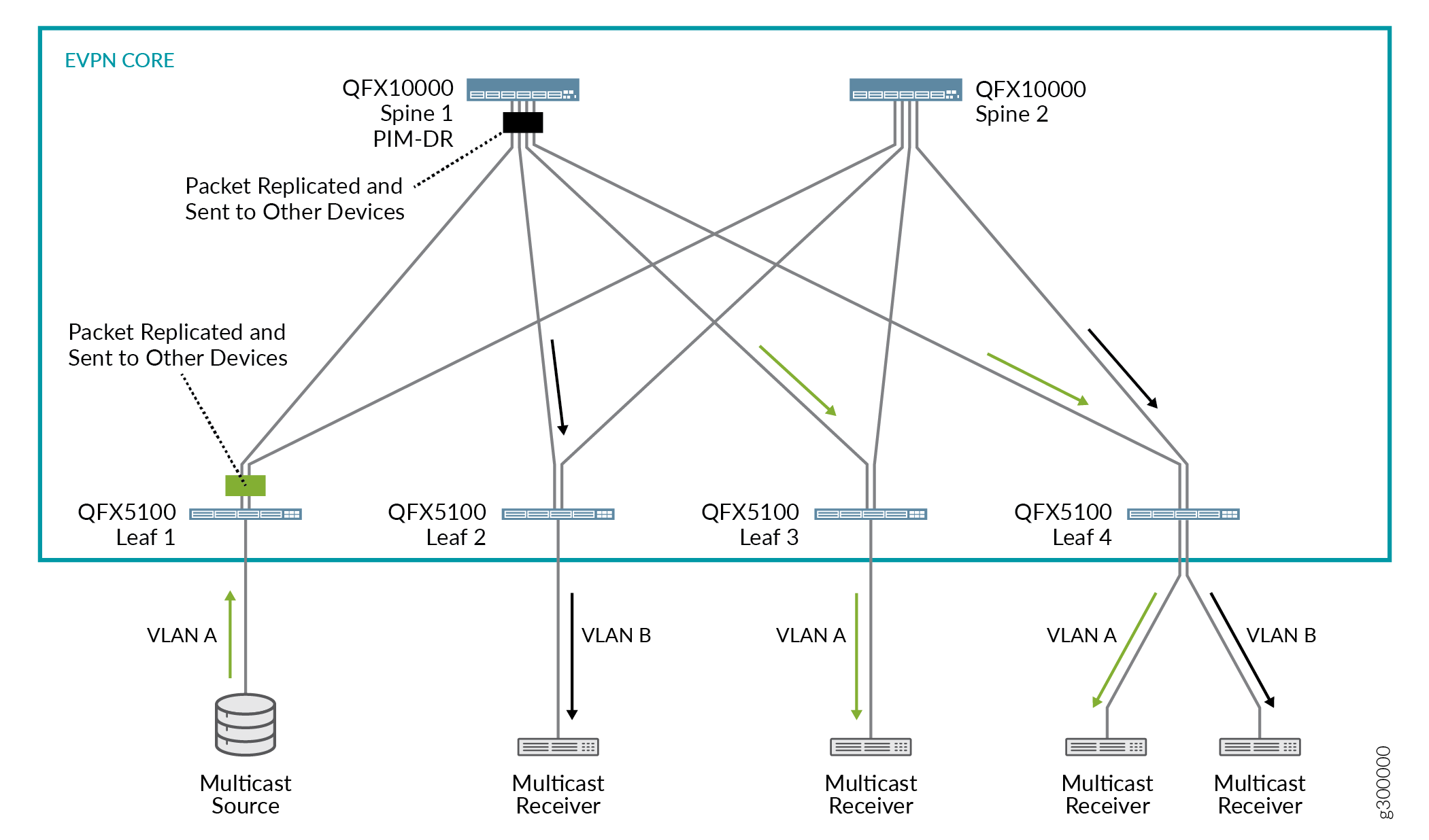
The network shown in Figure 1 includes the following devices.
-
Two QFX10000 switches that function as Layer 3 spine devices, on which the following key features are configured:
-
Centrally-routed (
local-remote) multicast forwarding mode. -
Protocol Independent Multicast (PIM). By virtue of PIM hello messages, Spine 1 is elected as the PIM designated router (PIM DR).
-
VLANs A and B.
Note:For inter-VLAN multicast forwarding to work properly in this scenario, you must configure all VLANs on each spine device.
-
IRB interfaces associated with VLANs A and B.
-
-
Four QFX5100 switches that function as Layer 2 leaf devices, on which VLANs A and B are configured are follows:
-
Leafs 1 and 3 are configured with VLAN A only.
-
Leaf 2 is configured with VLAN B only.
-
Leaf 4 is configured with VLANs A and B.
-
-
A multicast source and various receivers.
When the multicast source shown in Figure 1 sends a packet from VLAN A, the following flows occur:
-
Flow 1: Intra-VLAN traffic—Based on the ingress replication mechanism, Leaf 1 replicates and switches the packet to all spine and other leaf devices. Leafs 3 and 4, on which VLAN A is configured, receive and forward the packet to the connected multicast receivers.
-
Flow 2: Inter-VLAN traffic—Upon receipt of the packet from Leaf 1 as described in flow 1, Spine 1, which is the PIM DR, takes the following action:
-
Routes the packet over the IRB interface associated with VLAN B.
-
Based on the ingress replication mechanism, replicates and forwards the packet to the other spine and the leaf devices.
Leafs 2 and 4, on which VLAN B is configured, receive and forward the packet to the connected multicast receivers.
-
Understanding Multicast Traffic Flows in an Edge-Routed Bridging Overlay
This section describes the multicast traffic flow in an edge-routed bridging overlay.
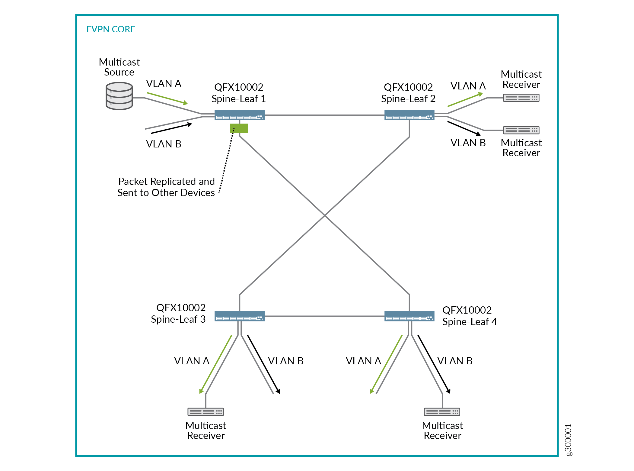
The network shown in Figure 2 includes the following devices.
-
Four QFX10002 switches that function as Layer 3 and Layer 2 spine-leaf devices, on which the following key features are configured:
-
Edge-routed (
local-only) multicast forwarding mode. -
PIM. To support the edge-routed mode of multicast forwarding, each spine-leaf device must act as the PIM DR for each VLAN. To enable a spine-leaf device to elect itself as the PIM DR, for each IRB interface, specify the
distributed-drconfiguration statement at the[edit protocols pim interface interface-name]hierarchy. -
VLANs A and B.
Note:For inter-VLAN multicast forwarding to work properly in this scenario, you must configure all VLANs on each spine-leaf device.
-
IRB interfaces associated with VLANs A and B.
-
-
A multicast source and various receivers.
When the multicast source shown in Figure 2 sends a packet from VLAN A, the following flows occur:
-
Flow 1: Intra-VLAN traffic—Based on the ingress replication mechanism, Spine-Leaf 1 replicates and switches the packet to the other spine-leaf devices. The spine-leaf devices forward the packet to VLAN A. Further, Spine-Leafs 2 and 3 forward the packet to VLAN A receivers.
-
Flow 2: Inter-VLAN traffic—Upon receipt of the packet from Spine-Leaf 1 as described in flow 1, the spine-leaf devices route the packet over the IRB interface associated with VLAN B. Further, Spine-Leafs 2 and 4 forward the packet to the VLAN B receivers.
Differences Between Inter-VLAN Multicast Forwarding Modes
There is an important difference between the centrally-routed and edge-routed modes.
With centrally-routed mode, for each VLAN, the spine device elected as the PIM-DR must replicate and send the packet to the other devices in the network. Keep in mind that the additional instances of replication consume bandwidth, and if many VLANs are configured, can potentially flood the EVPN core with multicast packets.
With edge-routed mode with the local-only model, the first spine-leaf device to receive a multicast packet replicates and sends the packet to the other spine-leaf devices. Upon receipt of the packet, the other spine-leaf devices route the packet to each VLAN and send the packet to access-side interfaces that handle traffic for the multicast receivers. In other words, the spine-leaf devices do not replicate the packet and send the packet out of the EVPN core-facing interfaces, which prevents excessive bandwidth consumption and congestion in the EVPN core.
Also note that the OISM model uses local routing, similar to the local-only model, to minimize multicast traffic flow in the EVPN core. However, with OISM, the leaf devices can also efficiently handle multicast traffic flow from sources outside the fabric to receivers within the fabric. OISM similarly enables multicast sources inside the fabric to send traffic to multicast receivers outside the fabric. See Optimized Intersubnet Multicast (OISM) in EVPN Networks for details on OISM configuration and operation.
Change History Table
Feature support is determined by the platform and release you are using. Use Feature Explorer to determine if a feature is supported on your platform.