ON THIS PAGE
Wireless Network Deployment (Juniper APs)
Access Point Staging
Access Point (AP) staging is the initial physical preparation of Juniper APs before their full deployment and configuration. This process begins with the careful unboxing of each AP, ensuring all components are present and undamaged. Following unboxing, physically mount the APs in their designated locations according to the detailed wireless site survey and low-level design. Address power requirements by connecting the APs to Power over Ethernet (PoE)-enabled ports on the Juniper EX-Series switches. These ports supply both data connectivity and electrical power, eliminating the need for separate power outlets. This streamlined staging ensures that the APs are ready for automated onboarding and configuration via the Mist Cloud.
- Unboxing and physical mounting of APs.
- Power via PoE from EX Switches
Juniper provides a wide range of hardware to support your wireless networking needs. All Juniper APs work in conjunction with the Juniper Mist cloud and Mist AI to deliver premium wireless access capabilities.
To quickly compare different models of APs, see the table below. For more detailed information, refer to https://www.juniper.net/us/en/products/access-points.html.
| Wi-Fi 6E (802.11ax) | Wi-Fi 7 (802.11be) | |||||||
|---|---|---|---|---|---|---|---|---|
| AP Model | AP24 | AP34 | AP45/E | AP64 | AP36/M | AP37 | AP47/D/E | AP66 |
| Deployment | Indoor | Indoor | Indoor | Outdoor | Indoor | Indoor | Indoor | Indoor - Outdoor |
| MIMO | 2x2:2 | 2x2:2 | 4x4:4 | 2x2:2 | 4x4:4 | 4x4:4 | 4x4:4 | 2.4 GHz:2x2:2 |
| Antenna | 2.4/6 + 5GHz | 2.4+5+6 GHz | 2.4/5/6+5+6 GHz | 2.4/6 + 5GHz | 2.4+5+6 GHz | 2.4+5+6 GHz | 2.4+5+6 GHz | 2.4/6 + 5GHz |
| Antenna | Internal | Internal |
Internal/ External |
Internal |
Internal/ Directional/ External |
Internal |
Internal/ Directional/ External |
Internal/ Directional |
| vBLE | No | No | Yes | No | No | Yes | Yes | Yes |
| Performance | Up to 3.6Gbps | Up to 4.2 Gbps | Up to 9.6 Gbps | Up to 3.6Gbps | Up to 11.53 Gbps | Up to 11.53 Gbps | Up to 28.8 Gbps | Up to 9.38 Gbps |
| PoE | 802.3af PoE | 802.3at PoE | 802.3bt PoE | 802.3at PoE | 802.3bt PoE | 802.3bt PoE | 802.3bt PoE | 802.3at PoE |
Selecting the Right Access Point
Choosing the right Juniper Mist access point (AP) from the AP36, AP37, and AP47 series depends on your specific environment and requirements for performance, antenna type, and deployment location.
- AP36: This is your go-to for standard indoor Wi-Fi 7 deployments. It offers solid performance with a 2x2 MIMO on the 2.4 GHz band and 4x4 MIMO on the 5 GHz and 6 GHz bands and a dedicated fourth radio for scanning. It's a great balance of essential Wi-Fi 7 features and cost-effectiveness for environments like offices, retail, and campuses that need reliable connectivity with high performance. The AP36 is designed for efficiency and streamlined deployments.
- AP37: The AP37 is similar to AP36 from a Wi-Fi perspective. It also features advanced location services with vBLE technology which can be used in digital transformation.
- AP47: The AP47 is the top-tier, highest-performance AP in the lineup. It's a four-radio, Wi-Fi 7 AP with 4x4 MIMO on all three bands and a dedicated fourth radio for scanning. The AP47 series is for the most demanding, mission-critical environments that need the absolute best performance, speed, and reliability. This includes large enterprise offices, stadiums, and high-density deployments where every millisecond of latency and gigabit of throughput matter. It also features dual 10 Gbps Ethernet ports for redundancy
Model Specifics (Antenna and Environment)
Once you've chosen the performance tier (AP36/37 or AP47), the suffix (D, E, or M) helps you select the right antenna configuration for your specific physical space.
- Standard Models (AP47, AP36, AP37): These are the general-purpose, indoor APs with integrated omnidirectional antennas. They're ideal for open office spaces, conference rooms, and other typical indoor environments where you need broad, uniform coverage. This is the most common choice for most deployments.
- AP47D: The 'D' stands for directional. This model has integrated directional antennas. You should select the AP47D for high-density environments where you need to control the signal and focus capacity in specific directions. Use it in lecture halls, auditoriums, or large meeting rooms where you want to serve a concentrated group of users without causing co-channel interference with other APs nearby.
- AP47E: The 'E' stands for external antennas. This is a flexible model, as it has connectors for external antennas. Choose the AP47E when you need to customize your coverage pattern for unique or challenging environments, such as large public venues, warehouses with high ceilings or high racks where you need to precisely aim the signal.
- AP36M: The 'M' stands for multi-directional. This model is unique to the AP36 series and is designed for indoor environments. It has a built-in directional antenna but can also use external antennas. The AP36M is a versatile option for spaces where you might need to combine omnidirectional coverage with a directional signal, such as warehouses with high ceilings, high racks or large open campus areas.
Onboarding Access Points
If you activated your subscription correctly as described previously, your APs are automatically onboarded into your Mist organization. If you would like to onboard APs individually or you would like to add more APs as an expansion to already claimed APs, then follow the steps: Onboard One AP Using the Mist AI Mobile App or Onboard One or More APs Using a Web Browser.
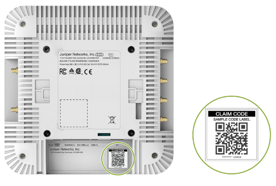
To perform either onboarding process, you will need to locate the claim code label on the rear panel of your AP. To onboard multiple APs, you can use the activation code that is listed in your purchase order (PO).
Access Point Mounting
You can mount the AP on the ceiling or wall using different methods. For instructions specific to your AP model, see the Mounting Instructions in the Appendix.
All APs ship with a universal mounting bracket that you can use for all mounting options. To mount the AP on a ceiling, you'll need to order an additional adapter based on the type of ceiling.
| Part Number | Description |
|---|---|
| APBR-U | Universal bracket for t-bar and drywall mounting. AP24s ship with the universal bracket APBR-U. If you need other brackets, you must order them separately |
| APBR-ADP-T58 | Bracket adapter for mounting the AP on a 5/8-in. threaded rod |
| APBR-ADP-M16 | Bracket adapter for mounting the AP on a 16 mm threaded rod |
| APBR-ADP-T12 | Bracket adapter for mounting the AP on a 1/2-in. threaded rod |
| APBR-ADP-CR9 | Bracket adapter for mounting the AP on a recessed 9/16-in. T-bar or channel rail |
| APBR-ADP-RT15 | Bracket adapter for mounting the AP on a recessed 15/16-in. T-bar |
| APBR-ADP-WS15 | Bracket adapter for mounting the AP on a recessed 1.5-in. T-bar |
Zero-Touch Provisioning for APs
Zero-Touch Provisioning (ZTP) for Juniper Mist Access Points is a key enabler for rapid and efficient wireless network deployment. Once the APs are physically connected and powered on, they automatically attempt to establish a secure connection to the Juniper Mist Cloud. Upon successful connection, the APs are automatically identified and onboarded to the cloud platform. From there, IT administrators can easily assign these APs to specific sites and overlay them onto digital floor maps within the Mist dashboard, streamlining inventory management, simplifying troubleshooting, and enabling location-based services without manual configuration on each device.
- APs automatically connect to the Mist Cloud.
- Assign APs to specific sites and maps.
Connectivity to Mist Cloud
With the initial setup tasks completed, you're now ready to verify that communication between the site and the Mist cloud is functioning properly. Ensure that all necessary network paths are open to allow seamless connectivity. Juniper APs need the following destination/ports to be enabled at your Internet Gateway or Firewall as below:
| Environment | Destination FQDN/Port |
|---|---|
| All clouds |
ep-terminator.mistsys.net (TCP 443) redirect.mist.com (TCP 443) |
| Global 01 | portal.mist.com (TCP 443) |
| Global 02 |
ep-terminator.gc1.mist.com (TCP 443) portal.gc1.mist.com (TCP 443) |
| Global 03 |
ep-terminator.ac2.mist.com (TCP 443) portal.ac2.mist.com (TCP 443) |
| Global 04 |
ep-terminator.gc2.mist.com (TCP 443) portal.gc2.mist.com (TCP443) |
| Global 05 |
ep-terminator.gc4.mist.com (TCP 443) portal.gc4.mist.com (TCP443) |
| EMEA 01 |
ep-terminator.eu.mist.com (TCP 443) portal.eu.mist.com (TCP 443 |
| EMEA 02 |
terminator.gc3.mist.com (TCP 443) portal.gc3.mist.com (TCP 443) |
| EMEA 03 |
terminator.ac6.mist.com (TCP 443) portal.ac6.mist.com (TCP |
| EMEA 04 |
terminator.gc6.mist.com (TCP 443) portal.gc6.mist.com (TCP |
| APAC 01 |
ep-terminator.gc7mist.com (TCP 443) portal.gc7.mist.com (TCP 443) |
| APAC 03 |
ep-terminator.gc7.mist.com (TCP 443) portal.gc7.mist.com (TCP 443) |
Refer to the following document for the exact port details for various cloud instances around the world:
Powering on the Access Point
When you power on an AP and connect it to the network, the AP is automatically onboarded to the Juniper Mist cloud. The AP onboarding process involves the following steps:
- When you power on an AP, the AP obtains an IP address from the DHCP server on the untagged VLAN.
- The AP performs a DNS lookup to resolve the Juniper Mist cloud URL. See Firewall Configuration for the specific cloud URLs.
- The AP establishes an HTTPS session with the Juniper Mist cloud for management.
- The Mist cloud then provisions the AP by pushing the required configuration once the AP is assigned to a site.
To power on your AP, connect an Ethernet cable from a PoE-enabled switch to the Eth0+PoE port on the AP.
An AP can connect to the Mist cloud with 802.3af power. However, most APs require 802.3at power at a minimum, whereas some APs require 802.3bt to operate with full functionality. Generally, 802.3at is the minimum recommended PoE power for APs. For information about PoE requirements for APs, see the table below:
| AP | Minimum PoE required | Wattage required for full operation |
|---|---|---|
| AP12 | 802.3af | 12.9W |
| AP24 | 802.3af | 13.0 W |
| AP32 | 802.3at | 19.5W |
| AP33 | 802.3at | 19.5W |
| AP34 | 802.3at | 20.9W |
| AP43 | 802.3at | 25.5W |
| AP45 | 802.3at/bt | 29.3W |
| AP63 | 802.3at | 25.5W |
| AP64 | 802.3af | 13.0 W |
| AP36 | 802.3at | 29.3W |
| AP37 | 802.3at | 29.3W |
| AP47 | 802.3at/bt | 29.3W |
| AP66 | 802.3at | 25.5W |
The AP45/47 requires 802.3bt for full functionality. On 802.3at, it has dynamic functionality based on what is configured.
- The AP will do 4×4 on any two data radios, or 2×2 on
2.4 GHz, 4×4 on 5 GHz, and 2×2 on 6 GHz with three data
radios enabled. For example:
- If your WLAN configuration only has two bands configured, the AP will operate as 4×4 on both data radios.
- If WLAN configuration has three bands configured, which means all three data radios are active, then the AP will operate as 2×2 on 2.4 GHz, 4×4 on 5 GHz, and 2×2 on 6 GHz.
You might need to enable the Link Layer Discovery Protocol (LLDP) on the switch for it to deliver 802.3at or 802.3bt power. If the switch that you are connecting the AP to is not PoE capable, use an 802.3at or 802.3bt-capable PoE Power injector. Juniper doesn’t carry 802.3bt power injectors in its product list, so we validated the “Phihong POE60U-1BT-5” as an 802.3bt power injector.
The AP should now appear as green (connected) in the Mist portal. You'll also notice that the status LED on the AP turns green, indicating that the AP is connected to the Mist cloud. Congratulations! You've successfully onboarded your AP.
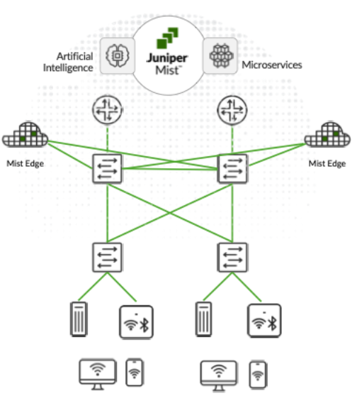
Mist Edge
Juniper® Mist™ Edge extends AI-native wireless agility and scale to the campus edge—without the need for legacy wireless controllers. Juniper Mist Edge allows data centralization, which is useful for organizations limited by legacy network designs, and for those that want seamless wireless mobility for guest and remote access.
When using Juniper Mist Edge, organizations gain the advantage of having localized data analyzed by the Juniper Mist microservices cloud and the Marvis AI engine. The unique combination delivers agility, reliability, and operational simplicity while enabling simplified, seamless, large campus roaming and secure IoT with dynamic segmentation. Having a Juniper AI-Native Networking Platform streamlines IT operations with unprecedented automation and insight.
With Juniper Mist Edge, organizations can deploy new microservices and upgrades easily on campus as the need arises. You can deploy and manage the network services you want, where you want them, in a consistent, seamless, and secure manner.
To quickly compare different models of Mist Edges, see the table below, and for more detailed information, refer to https://www.juniper.net/us/en/products/access-points/juniper-edge-datasheet.html.
Note: Mist Edge ME-VM is not a supported tunnel termination platform for production environments. The ME-VM has different use cases as a proxy for a non-Juniper product with Access Assurance.
| ME-X1-M | ME-X2-M | ME-X6 | |
|---|---|---|---|
| Max AP | 500 | 2000 | 5,000 |
| Mac Client | 5000 | 20,000 | 100,000 |
| Performance | 4 Gbps | 40 Gbps | 100 Gbps |
| Interfaces | 4x1000Base-T | 4x10GbE | 4x25GBase-X |
| Optics | N/A | SFP+ | SFP28 |
Wi-Fi Assurance Configuration
Wi-Fi Assurance Configuration is a cornerstone of optimizing wireless user experiences through Juniper's AI-Driven platform. This step involves enabling the WiFi Management and Assurance subscription within your Organization. Once enabled, IT teams can configure specific Wireless Service Level Expectations (SLEs) that align with organizational performance goals, such as connection success rates, throughput, and roaming performance. The Mist AI engine continuously monitors wireless client experience against these defined SLEs, proactively identifying and diagnosing issues, providing actionable insights, and automating troubleshooting to ensure a predictable, reliable, and measurable Wireless network experience for all users.
- Enable WiFi Management and Assurance service in Mist Cloud.
- Configure Wireless SLEs and monitor wireless client experience
As illustrated in this document, we have two main deployment approaches, distributed and centralized (tunneled). In this section will explain the basic configuration for the distributed approach.
Radio Settings (RF Template)
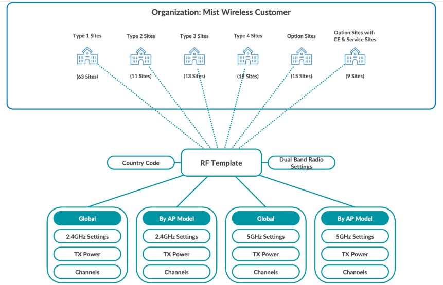
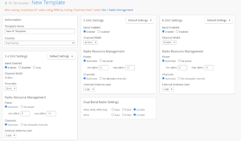
RF Templates provides a way to make uniform radio configurations that are shared by all APs and sites in your organization. RF Templates do this while simultaneously allowing for model-specific exceptions to cover different use cases that may occur with specific APs or individual sites. Settings include enabling or disabling radio bands, managing channel width, setting transmission power, and configuring AP antenna gain.
AP-specific default settings are available for all AP models when the Default Settings menu is active for each radio band. You can select specific AP models from the Default Settings menu to create model-specific exceptions within the RF Template. In this document, we assume you do one RF template for all APs within the site (Default Settings).
From the Mist left-nav menu, select Organization > RF Template and either choose an existing template from the list that appears or click the Create Template button to create a new one.
- Template Name—This is the name that appears in the templates list on the RF Templates page.
- Country—Your selection here determines which radio channels, and which power level defaults are available for configuration. If you keep the country setting on Any Country, the power limit and channel availability is dictated by the Country (radio frequency regulatory domain) selected in Organization > Site Settings.
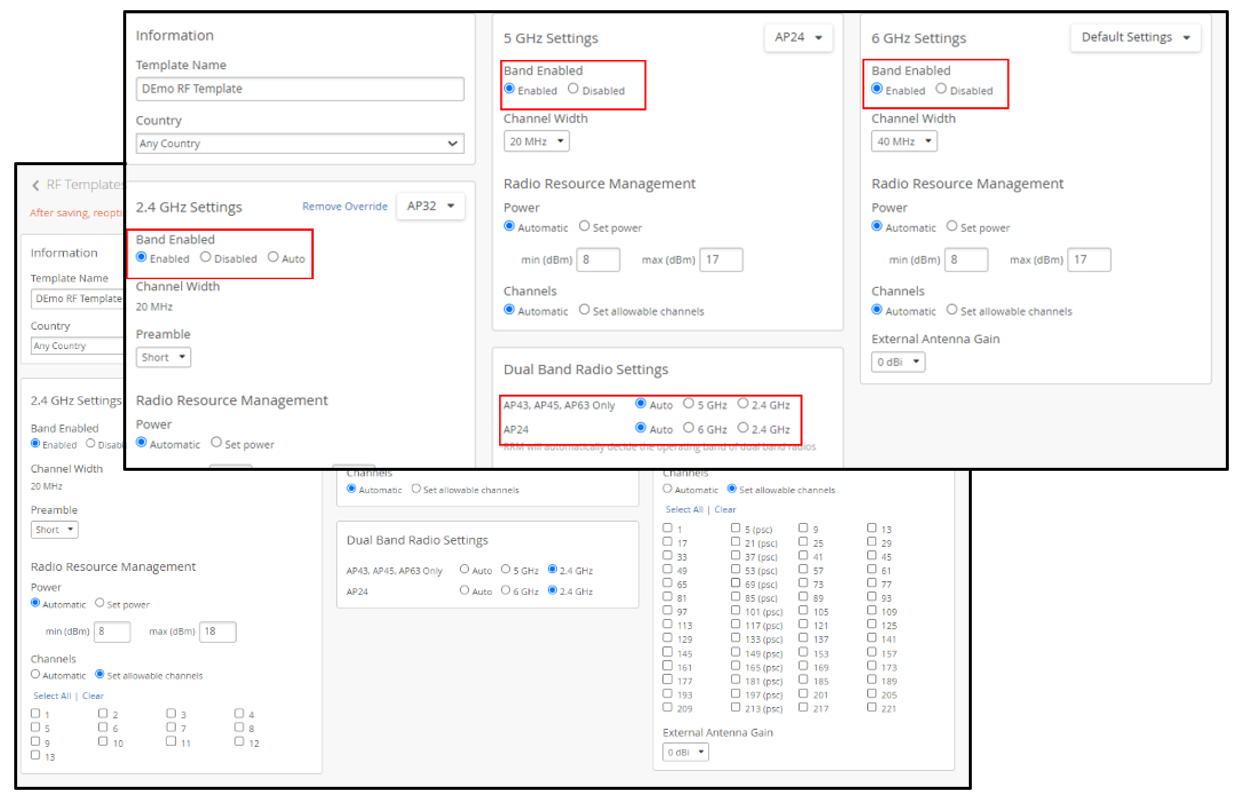
- Enabled/Disabled—Turn on or off the given radio band for
all APs in the template.
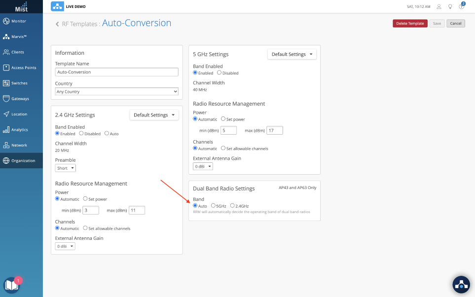
- Auto—When enabled for the 2.4 GHz radio band, auto will manage the 2.4 GHz radio band on the AP to maximize performance. For APs that support dual-band, this setting will convert the 2.4 GHz radio to 5 GHz or to 6 GHz based on regularly occurring Radio Resource Management (RRM) analysis. APs that support dual 5GHz are the AP43, AP45, AP63, and AP47. APs that support 6GHz are the AP24 and AP47. RRM can turn off the 2.4 GHz radio on APs that don't support auto-conversion, so the AP offers only the 5 GHz band. If RRM finds that doing so, it will improve network performance.
- You can select Auto for either the 2.4 GHz band, or for Dual Band Radio Settings in the RF Template configuration page, as shown below.
- If you enable dual bands, make sure you select narrow channel widths like 20 MHz on the 5GHz band or use directional antennas to avoid high spectrum utilization.
- The table below describes the modes of AP radio operation when different band settings are combined.
| 2.4 GHz Mode | Dual Band Setting | Mode of Operation |
|---|---|---|
| Enabled | Auto |
RRM to decide the band of dual band radios (auto conversion), applies for - AP43, AP45, AP63 (2.4 GHz/5 GHz) - AP24 (2.4 GHz/6 GHz). - AP47 (2.4 GHz/5 GHz or 6 GHz) - AP36 (2.4 GHz/5 GHz or 6 GHz) - AP37 (2.4 GHz/5 GHz or 6 GHz) - AP66 (2.4 GHz/5 GHz or 6 GHz) |
| Enabled | 5GHz | AP36, AP37, AP43, AP45, AP63, AP66 and AP47 will be in Dual 5 GHz mode. Where both radios are operating in 5 GHz band |
| Enabled | 2.4GHz | The radio will be set to 2.4Ghz. |
| Enabled | 6GHz |
AP24 will be in 6GHz +5 GHz operating mode AP36, AP37, AP47, and AP66 operate in dual 6 GHz + 5 GHz |
| Auto | 2.4GHz | Allow RRM to decide to enable or disable 2.4 GHz per AP (auto cancellation). Applies to all AP models. |
- Channel Width—For the 5 GHz and 6 GHz radio bands, you can set the channel width for all APs in the template. The 2.4 GHz radio band uses a fixed 20 MHz channel width. If required, you can specify which channels the radios can use in each radio band.
- Preamble— A preamble is a set of bits within a packet
header sent from an AP to a client that synchronizes transmission
signals between the sender and receiver. The options for the
Preamble are as follows:
- Unconfigured — This means the preamble will not be sent from the AP to the client.
- Short — (Default) This applies to the 2.4 GHz radio band only. This results in faster synchronization but requires clients to have the short preamble bit set in their association requests. Not all client implementations can support this setting. If you see association failures such as "client does not support short preamble," you can change the preamble that the AP sends to clients.
- Long — This results in slower synchronization but supports a wider range of clients.
- Auto — This results in slower synchronization but supports a wider range of clients.
- Power—This is the maximum transmit power allowed for a
given data rate per transmit chain. Note that because total power
out typically includes any MIMO gain, you should deduct MIMO gain
from the total power output (TPO) when configuring transmit power.
- The TPO for Juniper APs is equal to the transmit power per radio chain, plus MIMO gain.
- For simplicity, you can use the general rule of thumb for MIMO gain value: 2 spatial streams (2x2) results in 3dB of MIMO gain, and 4 spatial streams (4x4) results in 6dB of MIMO gain.
-
For example, if you configure any Juniper 4x4 Access Point with 17 dBm per chain, you then add 6 dB as the MIMO gain, resulting in a total transmit power of 23 dBm.
- Channels—For the 5 GHz and 6 GHz radio bands, you can set the allowable channels (for your selected country) for all APs. When set to automatic, all allowed channels in the selected country are available. For 6 GHz, the preferred scan channels (PSC) are as defined by the IEEE. The EU, for example, allows half the 6 GHz channels allowed in the USA.
- External Antenna Gain—Mist supports 1 dBm increments (although we recommend using a range of plus or minus 3 dBm from the median value indicated in a site survey predictive design). For example, some external antennas are certified up to a certain level of gain, which depends on the combination of AP and antenna. To prevent the gain from exceeding the maximum allowed for a particular AP model and regulatory domain, you can adjust this setting.
In addition to the RF Templates page described here, you can configure RRM variables and other settings in Organization > Device Profiles, in Site > Radio Management > Radio Settings, and individually on each Juniper AP. To understand the relationship and interaction between settings on these different levels see below.
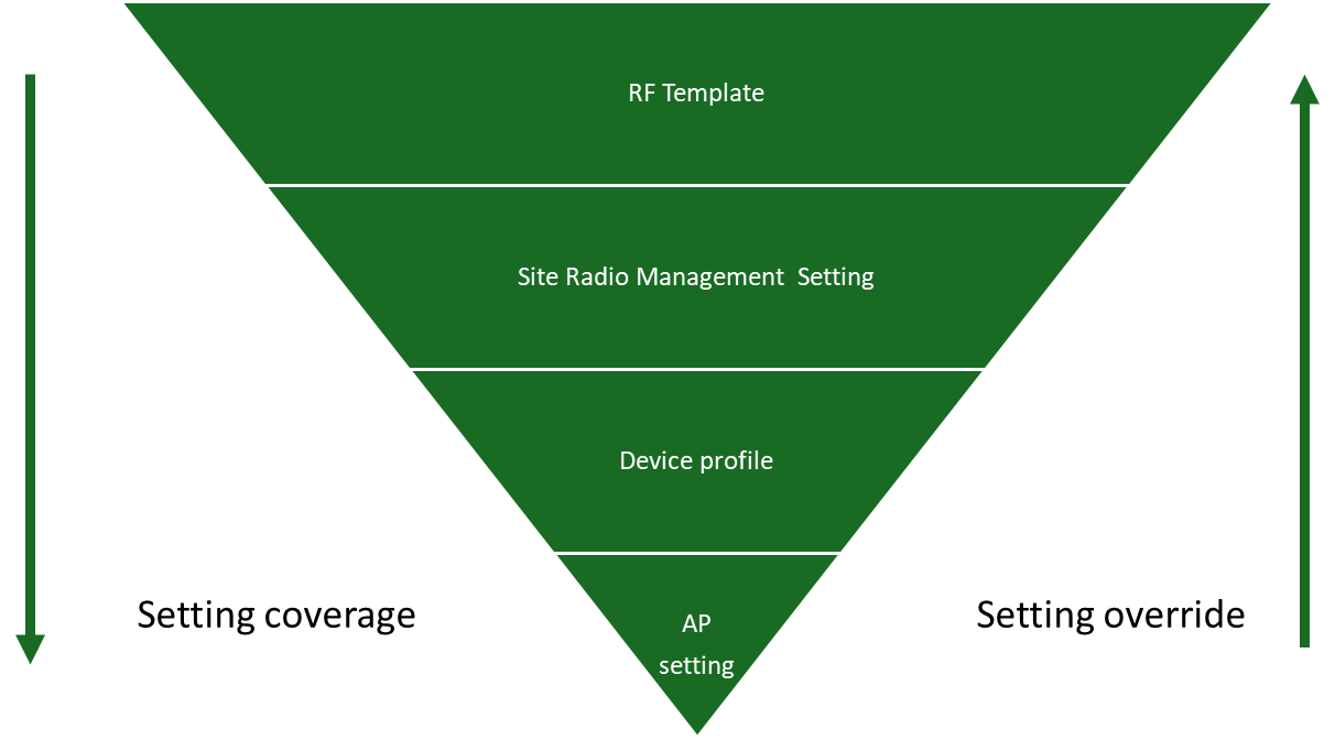
- RF Template—Configure all APs within a site or sites by leaving the Default Settings menu at Default Settings. Configure specific AP models within a site or sites, by choosing the specific AP model from the Default Settings menu.
- Site > Radio Management > Radio Settings— Configure all APs within the site or specific AP models within the site. Settings made on this page override RF Template settings.
- Organization > Device Profiles—Configure all APs mapped to the Device Profile and override settings in both the RF Template and Site > Radio Management > Radio Settings.
- Access Point setting—Configure a specific AP and override all other settings.
Juniper RF Template Recommendation
In the RF world, the optimal configuration depends on many variables that affect the installed base, such as interference, AP placement, antenna type, number of users, usage patterns, etc. Juniper recommends following best practices and making certain assumptions. Therefore, after the initial configuration, be sure to review the site Radio Management Site Summary statistics (Site > Radio Management) in addition to the SLEs to monitor the health of your network.
- Country.
- Select the country where you plan to deploy the AP.
- 2.4GHz settings configuration block:
- Default Settings menu—When Default Settings is selected, the configuration settings you make in the settings block apply to all APs in the organization. To use a different configuration for a specific AP model, select that model from the menu and make your changes in the configuration block. You can make changes to one or more APs using a Device Profile. You can also make changes to individual APs by editing the AP itself from Access Points > AP Name.
- Band Enabled: Enabled.
- Preamble: Short
- Power: Automatic with power range from 5 – 12 dBm
- Channel: Automatic
- External Antenna: add the value of your antenna gain if you are using an external antenna.
- 5 GHz settings configuration block:
- Default settings option (if you need to make an override configuration for any model type) then you can select the model (change default setting to a specific model) or do it using device profile.
- Band Enabled: Enabled.
- Channel Width: 40 MHz.Note:
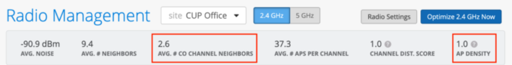
Monitor the Radio Management Site Summary statistics for 5 GHz as shown in the figure below. If the value of AP Density > 0.7 or the AVG. # Co Channel Neighbors > 1, change the channel width to 20 MHz. We recommend that you don’t use 80 MHz as the channel width in any enterprise deployment.

-
Power: Automatic with a power range from between 5 dBm min to 17 dBm max, depending on the maximum power allowed in the local regulatory domain.
Note: We highly recommend that you maintain the 5 GHz power setting between 3 to 6 dBm higher than the 2.4GHz power maximum to motivate clients to associate with 5Ghz for better performance.
- Channel: Automatic.
- External Antenna: add the value of your antenna gain if you are using an external antenna.
- 6 GHz setting:
- Default Settings menu—When Default Settings is selected, the configuration settings you make in the settings block apply to all APs in the organization. To use a different configuration for a specific AP model, select that model from the menu and make your changes in the configuration block. You can make changes to one or more APs using a Device Profile. You can also make changes to individual APs by editing the AP itself from Access Points > AP Name
- Band Enabled: Enabled
- Channel Width: 80 MHz (in FCC domain) and 40 MHz (in ETSI domain) due to channel availability per domain. Monitor the Radio Management Site Summary statistics, as you would for 5 GHz.
-
Power: Automatic with a power range from between 5 dBm min to 17 dBm max, depending on the maximum power allowed in the local regulatory domain.
Note: We highly recommend that you maintain the 5 GHz power setting between 3 to 6 dBm higher than the 2.4GHz power maximum to motivate clients to associate with 6Ghz for better performance.
- Channel: Automatic.
- External Antenna: Add the value of your antenna gain if you are using an external antenna.
Below is a sample of the RF template that works for most of the use cases.
The following examples show how you can adjust for different use cases:
- Enterprise Deployment designed for high-density 5 GHz or 6 GHz
Take a typical enterprise deployment that has been designed for high-capacity 5 GHz or 6 GHz. If we look at the co-channel and density metrics on the Radio Management Site Summary (Site > Radio Management) for 2.4GHz, we see each AP has an average of 2.6 co-channel neighbors. The density metric is 1.0. This site would be a great candidate for auto cancellation or auto conversion.
To enable auto conversion, simply select “auto” under Dual Band Radio Settings in the RF Template and assign the RF Template to a site.
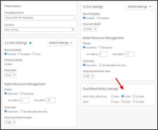
- Auditorium Deployment designed for high-density dual 5 GHz
The final example is an auditorium, conference room, or other area with higher-than-normal client density, where you may want to configure dual 5 GHz on all the APs in the site.
If yours is a mixed environment where you want to enable dual 5GHz in some areas but not in others, then you need to leverage the device profile.
To enable dual 5 GHz radios, simply select the 5 GHz radio button in the Dual Band Radio Settings block as shown below.
SSID and Security Policy Configuration
- Service Set Identifier (SSID) and Security Policy Configuration
are fundamental aspects of defining the wireless network's
accessibility and security posture. This involves creating the
various SSIDs that are broadcast by the
Juniper Access Points. You can configure separate SSIDs for
corporate users, guest access, and dedicated IoT devices. For each
SSID, meticulous configuration of authentication methods is
required, ranging from robust WPA2/3-Enterprise with RADIUS
integration for secure user and device authentication to simpler
Pre-Shared Keys (PSK) authentication or open networks for specific
use cases. SSID and Security Policy configuration also includes:
- Create SSIDs (for example, Corporate, Guest, IoT).
- Configure authentication methods (WPA2/3-Enterprise, PSK, Open).
- Integrate with RADIUS/Identity Management systems.
- Implement dynamic VLAN assignment based on user/device roles.
WLAN Templates
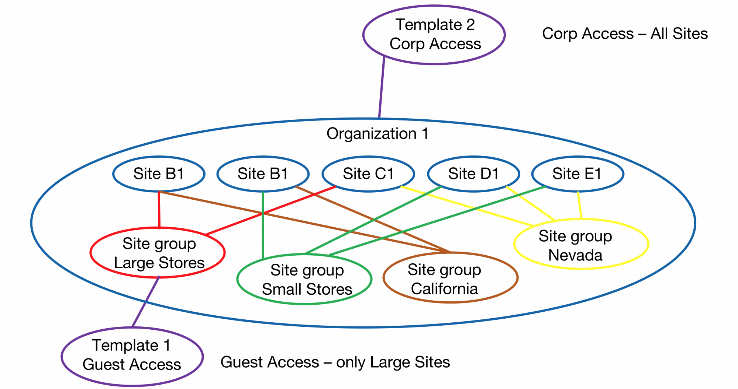
In Juniper Mist you can create the WLAN (SSID) either directly from the Site > WLANs page or from the WLAN templates page at Organization > WLAN Templates. The main benefit of using a WLAN Template is that the template can be assigned to one or more sites or an entire organization. This flexibility allows for consistent, repeatable configuration at scale and enables fast changes to all APs at once. Direct WLAN configuration at the Site > WLANs level only applies to that single site.
Templates are very useful for automation, but not really if there is only 1 site. For example, a guest template could be created with a WLAN, a tunneling policy, and a WxLAN policy and applied to the entire organization. After application, every AP in the organization broadcasts the guest WLAN.
Consider an IoT template. This could, again, contain everything to enable IoT and be tied to a site group called IoT. When a new site is deployed, the IoT devices at that site become part of the site group, and the IoT WLAN is instantly available.
Configure a WLAN template
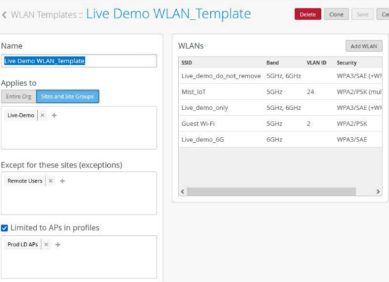
In the Juniper Mist portal, wireless LANs (WLANs) are modular elements that contain the security and other configuration settings for a service set identifier (SSID). A WLAN template is a collection of WLANs, access policies, and tunneling policies that you can use to streamline WLAN configuration and management at the organizational level.
WLAN templates are modular and can be attached to different sites or device profiles. In this way, you can mix and match whichever permutation of WLAN, site, and APs you need to cover all the use cases in your organization. Your wireless clients will only see the SSIDs you want them to see.
When working with WLAN templates, it's generally best to create them after you've set up your sites, either before or after claiming the APs. To keep things clear in the Mist portal, it helps to give the WLAN template the same name as the WLAN (SSID), which is what the clients will see. The idea behind all this is that once all your sites, WLANs, WLAN templates, and device profiles have been created, it will then be easy to make the associations.
For each template, you can select which APs to include, that is, which APs will broadcast the SSID. If the settings in each WLAN or WLAN template conflict with those specified for a given AP, or with those applied elsewhere to the site, you will be prompted to select which setting should take precedence.
To create a WLAN template, follow the instructions here: Configure a WLAN Template.
See WLAN Options for information about the configuration options in WLANs and WLAN Templates.
Juniper WLAN Template Recommendation
General Guideline
WLAN configuration varies based on multiple factors such as user device compatibility, coverage, interference, capacity, and business requirements. In this section, we provide some examples of WLAN templates and WLAN settings using the best practices. Refer to Wi-Fi Design Fundamentals for considerations and recommendations for wireless band selection and planning.
WLAN Setting Guidelines
Below is the recommended common configuration for a WLAN.
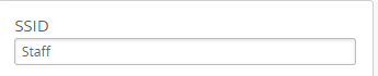
- SSID: Make the name relative to the service you intend to provide (like Guest for guest network or Staff or Employee for employee services). It’s not mandatory, but it helps the user connect to the right SSID.
- WLAN Status: Enabled—Allow the APs to broadcast the SSID
- Hide SSID: Unchecked—Some clients have issues connecting to hidden SSIDs.
-
Radio Band: Select (Check) all three bands if you have AP45s or AP34s that have all three radios available—Enabling all three radio bands to provide better network capacity. If you have some APs that don’t support 6 GHz, then select 2.4 GHz and 5 GHz only.
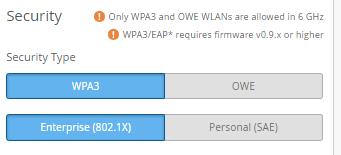
Note: Enabling the 6 GHz radio band forces you to choose WPA3 or OWE as the SSID Security Type, thus eliminating the less secure options.
- Band Steering: Disabled—Many client devices have issues with band steering.
- Client Inactivity: keep the default value of 1800 because most clients and applications run smoothly with this setting.
- Geofence: For most deployments, keep it disabled except if you need to enable it.
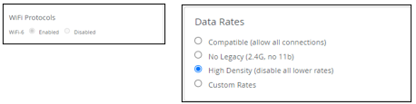
- Data Rates: If you don’t have legacy user devices in the network using this WLAN, select the option High Density ( disable all lower rates). This setting enhances the WLAN (SSID) utilization, enhances the client roaming experience, and reduces the occurrence of “sticky clients.”
- WiFi Protocols: Mist enables both Wi-Fi Protocols, WiFi 6 and WiFi 7, when you create a new WLAN, regardless of whether you create the WLAN in a template or directly on the site. There are a large number of clients that support WiFi 6 at the time of writing this document. We recommend that you leave WiFi 6 enabled. WiFi 7 client support still varies widely as does the support of individual WiFi 7 features. It is safe to turn off WiFi 7 if you don't have any WiFi 7 APs.
- WLAN Rate Limit: (Disabled by default) We recommend leaving this disabled unless you have a specific need for it. For example, you could rate limit the entire WLAN, rate limit each client device or limit specific applications on a guest network to prevent guests from overutilizing the services, which could affect other guest users or the network in general.
- Apply to Access Points: This is set to All APs by default. Optionally, you can apply the template only to APs tagged with a specific label, such as lobby, or apply the template to a list of specific APs.
-
Security:
The setting you
chose here is use-case dependent. The list below describes some of
the use cases.
- For staff and registered students, if your network uses an existing IDP or RADIUS for authentication, we strongly recommend configuring WPA3-Enterprise. Use Mist Access Assurance if available or configure a local RADIUS server.
- For secure access in small deployments or when no IDP/RADIUS is available, use WPA3-Personal (SAE) or WPA2-Personal (PSK). We strongly recommend WPA3-Personal for enhanced security, provided all client devices support it.
- For guest access, use the built-in guest portal for landing and authentication. Set WLAN security to OWE or Open Access. We recommend OWE for stronger security, if supported by guest devices.
- For IoT and BYOD deployments, use
the Multi-Pre-Shared Key
(mPSK) framework. We support
both WPA2 and WPA3:
- WPA2-mPSK supports local AP-level lookup, cloud-based PSK, and RADIUS integration.
- WPA3-mPSK currently supports RADIUS-based lookup only.
- We recommend WPA3 where device compatibility is allowed for stronger encryption and policy enforcement.
- To enable MAC Authentication Bypass (MAB), configure RADIUS lookup alongside SSID security settings such as Open, OWE, WPA2-Personal, or WPA3-Personal.
- VLAN: Juniper recommends assigning a dedicated VLAN per WLAN to minimize Layer 2 broadcast domains and improve performance and security. You can map the WLAN to a tagged VLAN, a VLAN pool, or a dynamic VLAN. Note that dynamic VLANs are supported only with WPA2 or WPA3-Enterprise security.
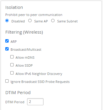
- Isolation: Isolation is disabled by default. Some use cases require client isolation on either the same AP or on the same Layer 2 subnet.
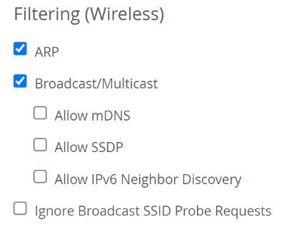
- Filtering: To optimize WLAN performance, enable ARP filtering and Broadcast/Multicast filtering. These settings reduce management frame traffic and free up radio airtime. Disable filtering only if required by specific application use cases.
- Custom Forwarding: By default, tagged or untagged client traffic is forwarded through the primary Ethernet port, Eth0. For distributed AP deployments, no changes are needed. For centralized deployments, alternative forwarding options will be covered in the next chapter.
- QoS Priority: The multimedia extensions, WMM and APSD, are enabled by default and should remain unchanged for most deployments. For specific use cases, you may override QoS settings to map all WLAN traffic to a defined priority level, such as Background, Best Effort, Video, or Voice.
- Bonjour Gateway: By default, this feature is disabled. Enable Bonjour Gateway for use cases like media or printer sharing in schools, or IPTV sharing in hotel rooms. To configure, select the desired service (for example, AirDrop, AirPlay, AirPrint, Amazon devices, GoogleCast, etc.), then define the service scope as AP, Site, or Floorplan.
Juniper WLAN Template Examples
In the previous section, we provided information about template settings, their defaults, and some best practices. In this section, we provide template use case examples to further illustrate best practices in specific scenarios.
Enterprise (802.1x) Based WLAN for Authorized Users
In this example, we configure a WLAN with Juniper best practices and recommendations. We use previously deployed, local RADIUS services. The illustration below explains the network architecture.
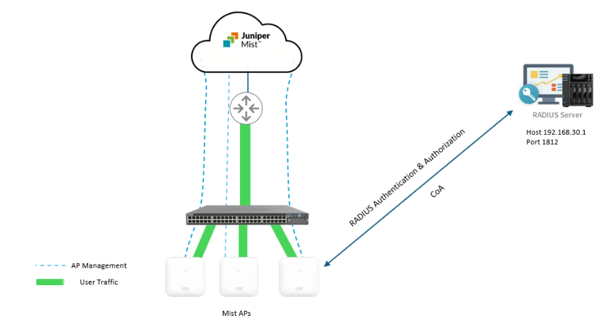
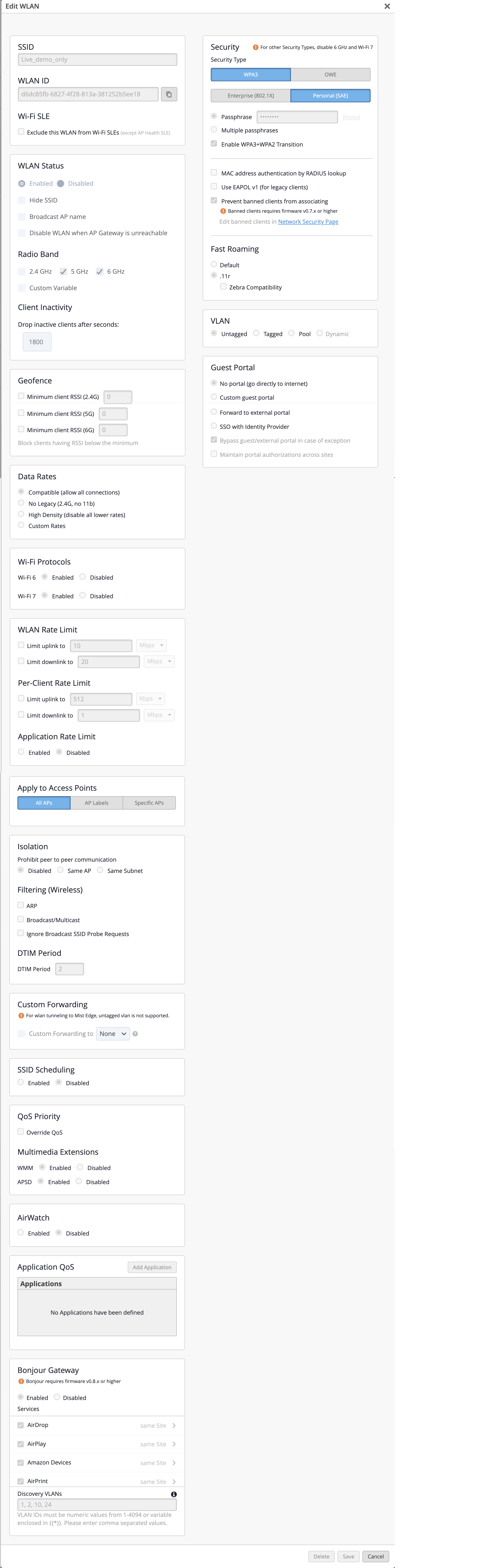
First, we apply the best practices settings shown in the list below
- Create a WLAN Template as explained earlier and add a WLAN to the template.
- In the WLAN settings, set the SSID name to Staff.
- Leave the WLAN Status set as Enabled.
- Enable all three Radio Bands (2.4, 5 and 6 GHz)
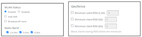
- Ensure all Geofence checkboxes are disabled (not checked).
- Select High Density (disable all lower rates) in the Data Rates block to avoid legacy devices and enhance network performance.
- Enable WiFi-6 in the WiFi Protocols block.
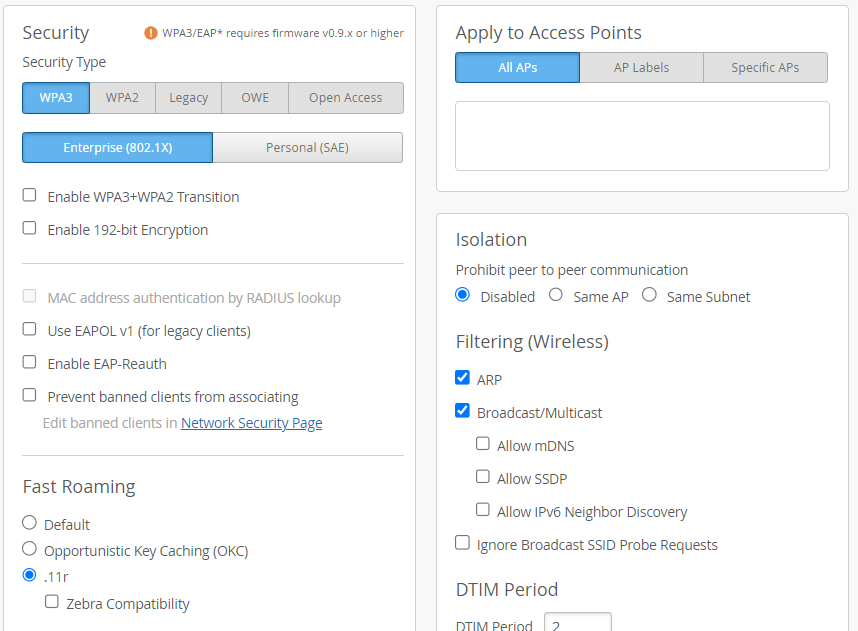
- In the Isolation block, enable the ARP, Broadcast/Multicast, and Allow mDNS checkboxes in the Filtering (Wireless) as shown below:
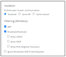
Leave the rest of the configuration blocks on the left side to set to their default values.
- In the Security block of the Create WLAN
window:
- Select WPA3 as the Security Type
- Select Enterprise (802.1X)
- In the Fast Roaming section, enable .11r

This setting is recommended if all your client devices support it. If not, enable Default.
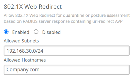
- In the 802.1X Web Redirect block, you can opt to redirect
clients to a webpage, such as a quarantined
portal, after they complete the 802.1X authentication.
Note: The 802.1X Web Redirect box is available only for WLANs with
security type Enterprise (802.1X). You can use the web redirect
feature to give clients full or partial access to the network. This
feature enables you to perform compliance checks on clients with
agents installed. During client authentication, the RADIUS server
sends an Access-Accept message containing a URL-redirect AVP to
point the client to a quarantined portal for remediation. When you
enable this feature, the client is initially restricted to DHCP and
DNS, specific subnets, and the specified redirect URL. When the
client completes the requested action within the portal, it is
fully authorized and allowed to start passing traffic.
- If you want to use the web redirect feature, select Enabled in the 802.1X Web Redirect section. Then, specify the allowed subnets and allowed hostnames accessible to the clients being redirected.
- In the Authentication Servers block, select RADIUS as the server type. Note: The Authentication Servers configuration block is available only when you've selected WPA3 and Enterprise (802.1X) under Security Type.
- Click Add Server under RADIUS
Authentication Servers.
- Type the IP address or DNS name of the RADIUS server in the Hostname field
- The port number field defaults to 1812. Change it if needed.
- Enter a shared secret then click the check mark (√) to save this RADIUS server.
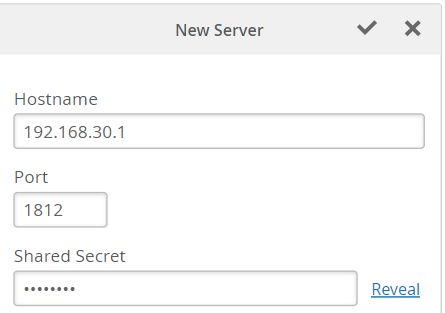
You can add multiple RADIUS servers for redundancy.
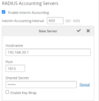
- Click Add Server under RADIUS Accounting Servers.
- Add the Accounting Server(s) in the same way you added the authentication server(s). In most cases, the accounting server is the same as the authentication server.
- Select (check) Enable the Interim Accounting so the AP can send periodic updates to the accounting server during the lifetime of user sessions. If it’s not enabled, the AP will send updates only at the start and end of the user sessions.
- Optionally, you can configure the NAS Identifier attribute. The NAS-Identifier is a user-configurable attribute value pair (AVP) that could be unique per WLAN configuration. All Mist APs configured with this WLAN send the NAS-Identifier value. Note that Mist Cloud allows dynamic payload configuration, such as sending the current AP hostname, Site name, AP MAC address, or AP model using pre-defined variables. See Configure Site Variables for information about variables. In this example, we set the NAS-Identifier to the name of the WLAN and the assigned Site name, using a variable, as shown below.
- In the CoA/DM Server block, you can add a CoA/DM server.
- Change of Authorization (CoA) allows you to modify authorized RADIUS sessions after initial authentication to meet changing access requirements. For example, enable use cases such as administrator-initiated session resets.
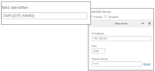
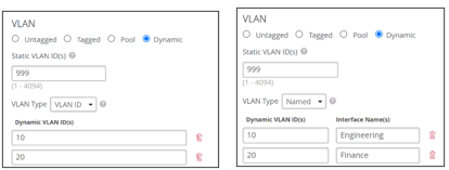
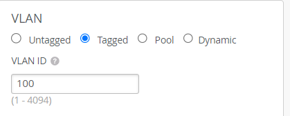
- In the VLAN block, select Tagged (static) or Dynamic. For Dynamic, we support Named VLAN (Airespace-Interface-Name) or VLAN ID. The images below depict example configurations using each method. The best method for your network depends on the capabilities of your RADIUS server.
After applying the above configuration, click Save in the Edit WLAN window.
Client Onboarding WLAN
For client onboarding, Juniper Mist provides automation and simplifies the process of secure wireless connectivity by leveraging the mPSK (Multi pre-Shared Key) capabilities provided by BYOD (SSO) using a simple portal to allow clients to provision access without IT involvement.
Benefits from Client onboarding – PSK portal:
- Automate client onboarding with a simple click-and-go flow.
- No legacy on-prem servers or appliances.
- Full control of onboarded clients including role based, validity and number of concurrent devices per PSK.
- Visibility into the usage of each PSK.
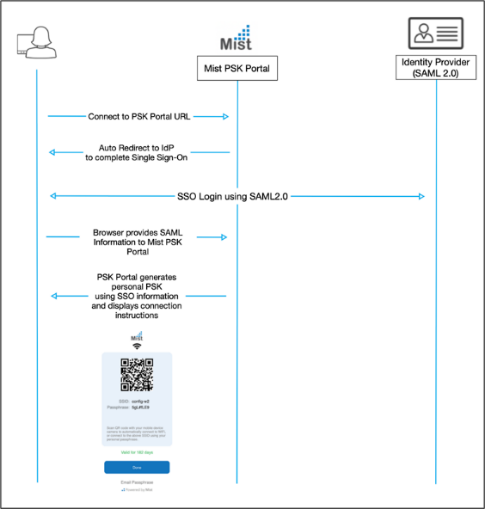
The Juniper Mist client onboarding portal allows users to self-provision their devices using multiple PSKs, in a BYOD portal, with simple portal redirection. The portal prompts the user to enter their credentials, and then an automated PSK is generated for that specific user according to configured Organization policy. The diagram below illustrates the workflow of the self-provisioning process.
- Prerequisites
- You must have a Mist Access Assurance subscription if you are
planning to use cloud-PSK
- S-Client-S-Y
- The Y reflects the number of years in the subscription 1, 3 or 5 years.
- mPSK ORG level SSID (WLAN) configured.
- SAML 2.0 Identity Provider with SSO
- You must have a Mist Access Assurance subscription if you are
planning to use cloud-PSK
Create the WLAN Template as explained earlier and add a WLAN in the template as shown in the steps below.
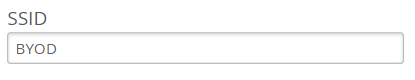
- In the SSID block:
- Name the SSID BYOD. The name is not mandatory, it’s easy to remember for this example.
- In the WLAN Status block:
- Leave the WLAN Enabled.
- Select 2.4 GHz and 5 GHz in the Radio Band section.
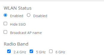
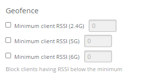
- In the Geofence block:
- Leave everything disabled (unchecked).
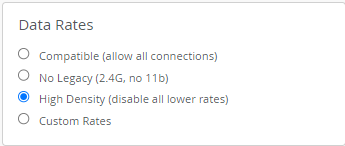
- In the Data Rates block:
- Enable (select) High Density ( disable all lower rates). This excludes legacy devices and enhances network performance.
- In the WiFi Protocols block:
- Leave WiFi-6 and WiFi-7 Enabled.
- Leave the WLAN Rate Limit block and Apply to Access Points blocks as-is.
- In the Isolation block set Filtering (Wireless) to:
- Enable ARP.
- Enable Broadcast/Multicast.
- Leave the remaining blocks down the left side of the Edit WLAN window as-is (keep the default values).
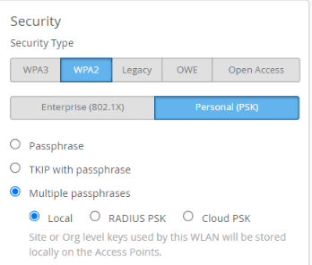
- In the Security block:
- Select WPA2, the supported encryption for mPSK with SSO onboarding).
- Select Personal (PSK).
- Select Multiple passphrases and Local. Local or Cloud PSK would work
here. We use Local for this example.
- In the Fast Roaming section, leave Default selected.
- In the VLAN block, select Tagged.
With those settings complete, you are ready to start the onboarding client configuration process. You must have an account with one of the identity providers that supports SSO and SAML 2.0 with user accounts. To allow users to onboard themselves, they must authenticate using their SSO. In this example we use auth0 as the SSO provider, but you can use any standard SSO provider with SAML 2.0 support.

To start, you must have an account with auth0. If you don’t have an account, register and create an account at https://auth0.com/signup?place=header&type=button&text=sign%20up.
- After you create an account, login to auth0 using the new account.
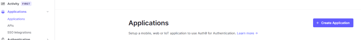
- Select Applications > Applications from left side main menu
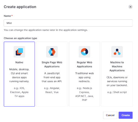
- Create an Application.
- Name your application Mist.
- Select the application you just created and click the Addons tab.
- Enable SAML2 Web App.

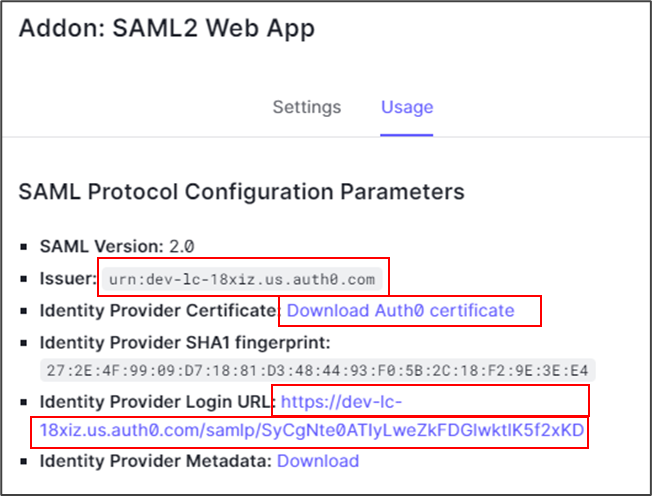
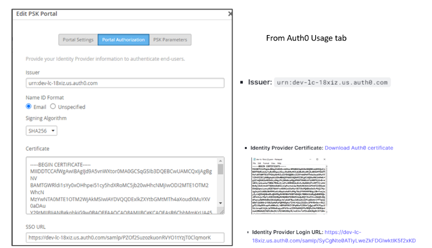
- Under the Usage tab on the Addon page, the SAML2 Web App Parameters display the Issuer, Identity Provider, and Identity Provider Login URL, all of which are required in the Mist portal for onboarding.
- Download and save the Identity Provider Certificate. Keep the other information handy for use in upcoming steps.
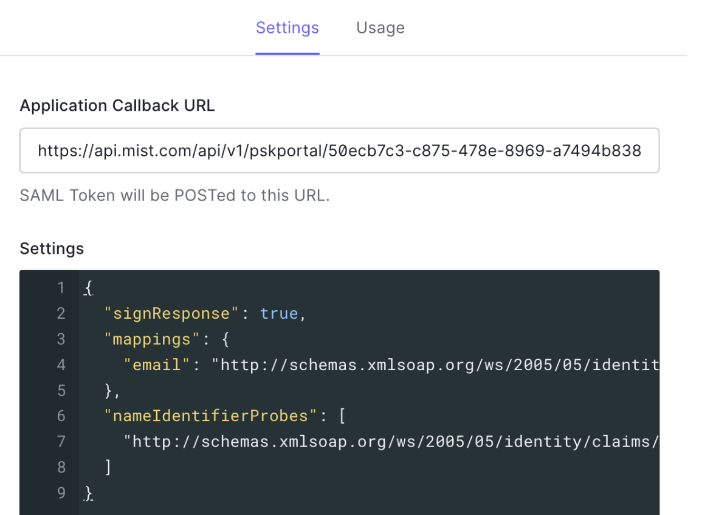
- Select the Settings tab and paste the text below into the
Settings window to replace (overwrite) the existing text in the
window.
{
  "signResponse": true,
  "mappings": {
    "email": "http://schemas.xmlsoap.org/ws/2005/05/identity/claims/userEmail"
  },
  "nameIdentifierProbes": [
    "http://schemas.xmlsoap.org/ws/2005/05/identity/claims/userEmail"
  ]
}
The result appears as shown below:
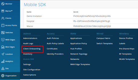
- Open a new tab in your browser and log in to your Mist portal at https://manage.mist.com.
- Go to Organization > Access > Client Onboarding.
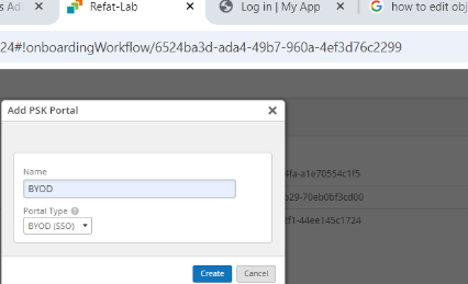
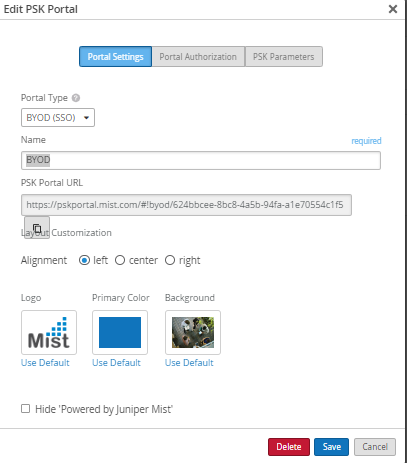
- Click Add PSK Portal. The Edit PSK Portal window appears.
- On the Portal Settings tab, enter a name for your PSK portal. For this example, call it BYOD and select BYOD (SSO) as the Portal Type.
- On the Portal Authorization tab, fill in the information as shown below. Use the information saved from the Auth0 > Mist App > SAML2 Web App Addons > Usage window above.
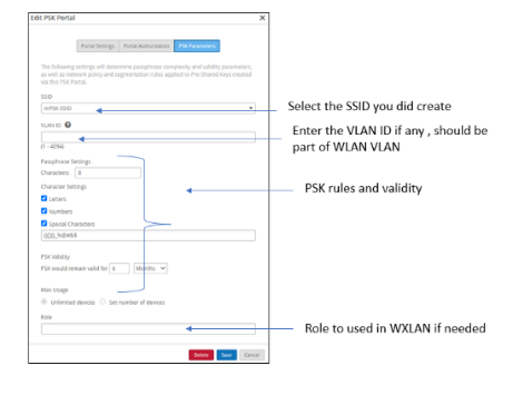
- Select the PSK parameters tab and fill in the information as illustrated in the figure below.
- After this step, save the configuration and open the configuration again, you will notice a new file has been generated. Copy the link as you need it in the next step, now go back to the auth0 tab in your browser from the previous step.
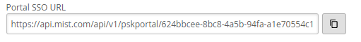
- In the Auth0 application you created previously, select the Settings tab. In the Application callback URL, past the URL link you copied (from the Mist > Client Onboarding > Edit PSK Portal) in the previous step.
- Enable the configuration in Auth0. This takes you back to the main screen where you click Save.
Now, we create a test user in Auth0. If you already have users in Auth0, you can skip this step.
- Select User Management > Users from the left menu. Click + Create User.
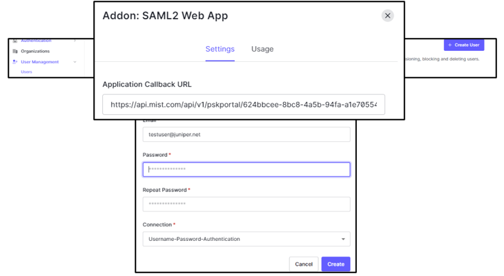
- Enter the Email and Password of your choice. Confirm the password if needed and click Create.
This completes the required configuration. When you open Mist Client Onboarding, the client list appears similar to the image below. Note that all the fields are filled out.
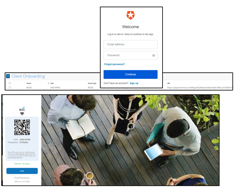
Upon logging in, the user is directed to the Auth0 SSO page for authentication. Upon successful authentication, the system redirects you to the Mist onboarding portal, where you can scan your code using your mobile and configure the SSID. Optionally, you can copy the information if no barcode scanning is available on your device. An email is sent to the user upon completion.
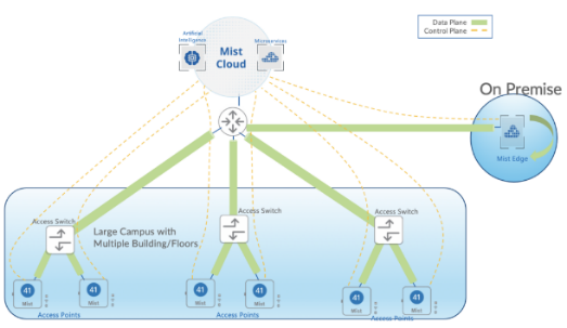
As mentioned previously, we have two main deployment approaches, distributed and centralized (tunneled). We explained the fundamental configuration for the distributed approach previously. In this section, we explain how to configure the centralized deployment.
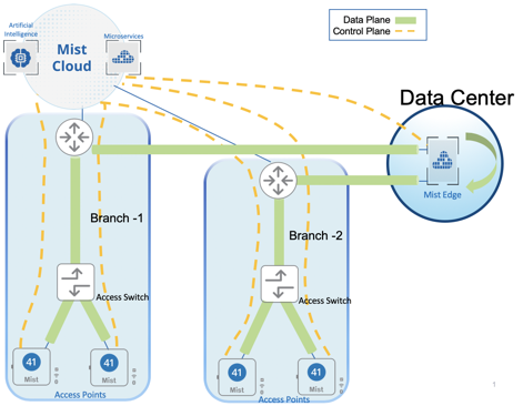
The Mist solution leverages Mist Edge devices for cases that need to retain a centralized datapath architecture for Campus and Branch deployments. These tunneled deployments provide the same level of redundancy and access to corporate resources, while extending visibility into user network experience and streamlining IT operations.
Juniper APs can form L2TPv3 tunnels to extend one or more VLANs from one or more Mist Edge devices located in Campus, Datacenter, or DMZ simultaneously. APs can support both local and centralized datapath at the same time.
How it works
The centralized solution leverages Mist Edge devices for extending centralized corporate, production, or guest VLANs to APs using L2TPv3 tunnels. The Mist cloud orchestrates the Mist tunnel; the datapath is maintained in the event the Mist Edge’s or AP’s cloud connectivity to the Mist cloud is lost.
- Mist Edge is based on multi-service architecture, so individual services can be upgraded as and when required with a 3-second downtime, with no need for a reboot.
- AP firmware and Mist Edge service version are decoupled; upgrading a Mist Edge device’s firmware does not also require an AP firmware upgrade.
- APs can form multiple tunnels to different Mist Edge clusters in the Site, the DMZ and the datacenter. You can map user traffic to be tunneled or locally bridged based on RADIUS attributes returned for 802.1x authenticated wireless LANs.
- APs can support tunneled and locally-bridged WLANs simultaneously. WLAN types are not mutually exclusive.
- Mist’s cloud-driven AI provides unprecedented user-experience visibility through the Service Level Expectations (SLE) framework and the AI-driven Marvis Engine that includes natural language processing for troubleshooting and root cause analysis, along with Marvis Actions. IT teams can leverage these Marvics features for remote troubleshooting of user issues.
In the centralized approach, we can employ either of two different use cases as shown below:
- Enterprise or campus
- Teleworkers and remote offices.
Mist Edge Configuration Components
Mist Edge offers a simple, yet powerful configuration scheme orchestrated by the cloud. The configuration objects needed to deploy Mist Edge in your network are discussed below:
- Mist Edge—Hardware or virtual appliance. Just like Juniper APs, Mist Edge hardware appliances come with a claim code that can be used in the Mist portal or scanned by a mobile app to add Mist Edge devices to an organization’s inventory. Within the Mist Edge configuration, you configure the Tunnel IP, which is the IP address or hostname, with which APs will form tunnels.
- Mist Edge Cluster—Mist Edge devices must be a part of a cluster to actively terminate tunnels from APs. A Mist Edge cluster can consist of one or more Mist Edge devices. Under normal operation, the members of a cluster are in active-active mode and load balance all the AP tunnels. The Mist GUI allows you to configure only a primary and secondary cluster. However, using the API, there is no limit to the number of Mist Edge clusters that you can configure.
- Mist Tunnels—The Mist tunnel object contains attributes that determine the tunnel protocol, endpoints, tunneled VLANs, failover timers, and more. The tunnel configuration decides the primary cluster and secondary cluster for AP tunnel termination. APs will load balance across Mist Edges in the primary cluster.
Mist Edge Onboarding
Verify your Mist Edge subscription before moving forward with configuring Mist Edge devices to avoid any subscription-related issues. You can verify Mist Edge subscription status by selecting the Summary tab on the Organization > Subscriptions page in the Mist portal. Contact your Juniper Mist partner or representative who can help by getting a quote for adding the Mist Edge subscription or raising a request for trial subscription.Mist Edge subscription is entitled on per AP basis, each AP tunneling requires a Mist Edge subscription.
Mist Edge onboarding is straightforward. There is no need for pre-staging. Mist Edge devices can be shipped directly to the branch or campus, installed, and brought online.
Claim on the Mist Dashboard
From the left-nav menu in the Mist portal, go to Mist Edges > Mist Edges Inventory > Claim Mist Edge.
Enter the claim code, which is provided on the purchase order or can be seen in the appliance pull-out tag. Alternatively, you can scan the QR code using the Mist AI app on Android or Apple mobile phones to claim individual devices.
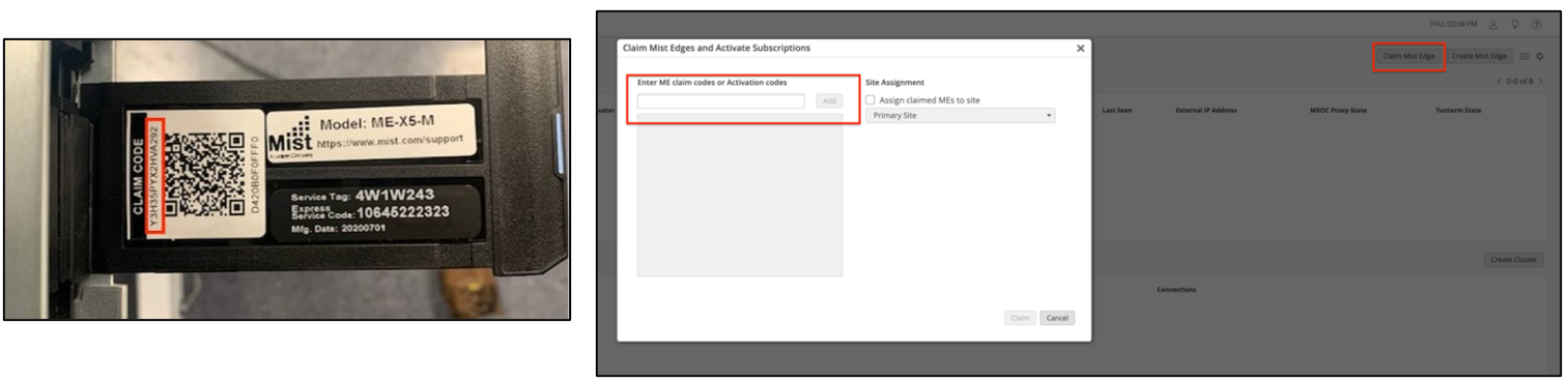
After you claim a Mist Edge device, it shows Disconnected and Registered on the Mist Edges page in the Mist portal.
Setup Mist Edge
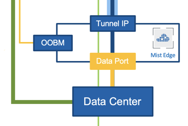
Mist Edge devices typically reside in the DMZ, Data Center (DC), or Campus with one arm connected to the Internet, and another arm connected to a trusted network. You must understand the physical port connections of Mist Edge devices before proceeding with configuration.
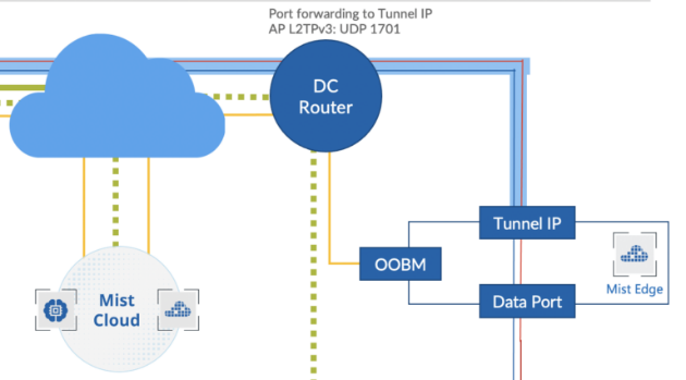
Physical Port Connections Overview
The following illustration shows Mist Edge port configuration requirements:
We strongly recommend that you configure the OOBM and the Tunnel Termination IP addresses on different subnets.
Configure OOBM
Connect the Out-Of-Band-Management (OOBM) port of the Mist Edge to an access-mode interface on your switch. Mist Edge devices use the OOBM port to communicate with the Mist cloud for configuration, telemetry, and lifecycle management. The following image shows the OOBM and other ports on a Mist Edge X1 appliance.
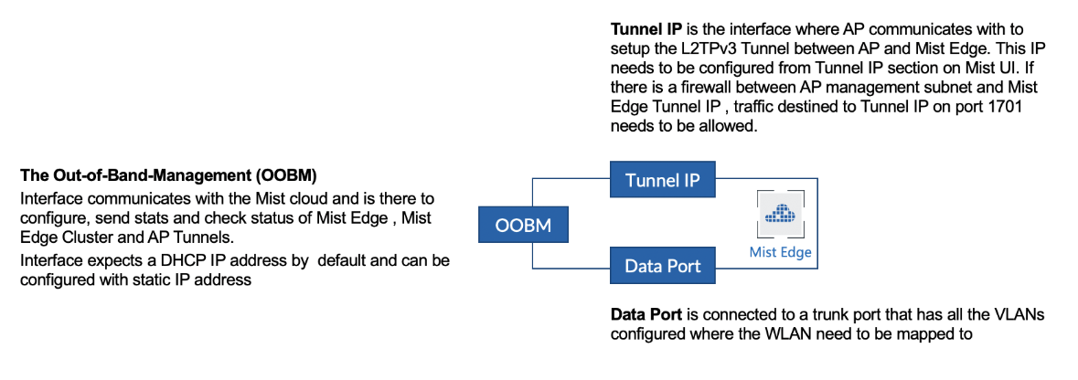
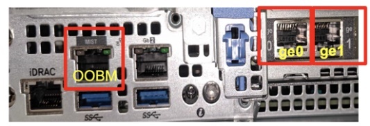
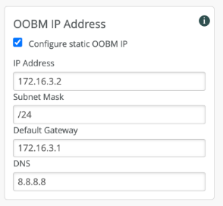
The OOBM port on the Mist Edge appliance is marked MIST. By default, the OOBM port is configured for DHCP. There are two ways to configure static IP depending on your network.
To configure a static IP, you can configure this from the Mist Dashboard. If your network has DHCP, it is recommended to first connect using DHCP to the cloud and then use the Dashboard to configure the static IP:
Go to Mist Edges > OOBM IP Address.
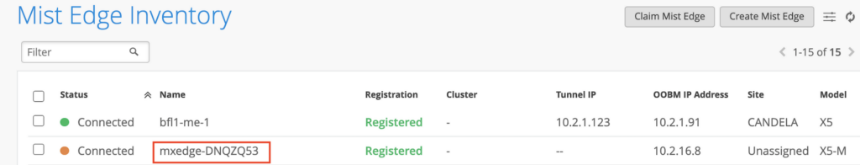
For Mist Edge to communicate with the Mist cloud, specific FQDNs and ports must be allowed for the OOBM interface. Refer to this link for the most up-to-date information: https://www.juniper.net/documentation/us/en/software/mist/mist-management/topics/ref/firewall-ports-to-open.html. You must use the region-specific FQDNs listed on that page since the IP addresses will change. Once the OOBM is configured and the firewall rules are in place, Mist Edge displays on the Mist Edge Inventory page as Connected (with an Amber dot as shown below).
In case the Mist Edge does not show connected even after 5 minutes, you can SSH to the Mist Edge appliance using the OOBM IP address. Once connected through SSH, you can use the device’s CLI to troubleshoot connectivity issues.
Configure Tunnel Termination Services
The Tunnel Termination Service listens to APs to request an L2TPv3 tunnel connection. The service is automatically installed once the Mist Edge is fully configured.
To prevent network disruptions, do not enable the switch connections to the Mist Edge data ports until after the Mist Edge device receives a Tunnel IP address, and the tunnel is configured.
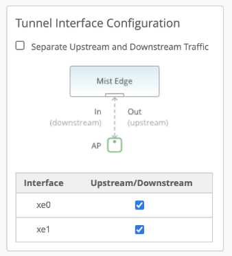
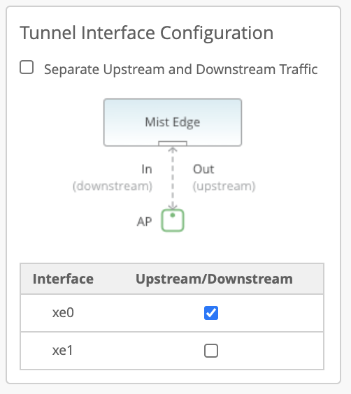
Dual Arms
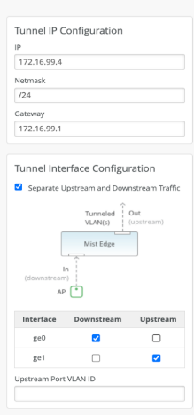
Mist Edge devices have multiple tunnel (data) ports, which you can configure as single-arm or dual-arm connections. When you select Separate Upstream and Downstream Traffic on the Mist Edge setting page if you create a dual-arm configuration. Assign the interfaces for upstream and downstream traffic as needed. In the example below, we show a Mist Edge X5-M or X10 on the left and a Mist Edge X1 on the right. The difference in Mist Edge devices appears in the name and number of available interfaces.
You connect interfaces xe0 and xe1 from the X5-M (or ge0 from the X1) to the Downstream (AP, public, or untrusted) side of the Mist Edge. L2TPv3 tunneled VLAN traffic enters the Mist Edge device at these connections from the APs. Interfaces xe2 and xe3 (or ge1) connect to the corporate (trusted) network and carry the tagged VLAN (user) traffic.

The Upstream Port VLAN ID is optional and should only be used when the upstream switch port is configured as an access port with a single, untagged VLAN.
For the tunnel IP configuration, add the IP address, subnet mask, and gateway as shown below. For a campus and branch deployment, the AP must be able to route to the Tunnel IP.
The Tunnel IP SVI on Mist Edge is a protected interface. Even if it is not connected to a firewall, the only open ports are UDP ports 1701 (L2TPv3), UDP 500 (isakmp), and UDP 4500 (IPsec), along with TCP port 2083 (RADSEC).
Mist Edge only uses UDP ports 500 and 4500, along with TCP port 2083 for the remote worker use case. For all other campus and branch use cases, Mist Edge only uses UDP port 1701.
As mentioned previously, upstream ports are connected to the trusted side of the network. These ports typically connect to your core (or aggregation) switch on a trunked port, configured to allow all the necessary user VLANs. Mist Edge carries L2-tagged traffic from the tunnels to here.
The downstream port is connected to the untrusted side of your network that typically goes to your firewall. The downstream port must be connected to an untagged interface.
Single arm
Instead of a dual-arm configuration, you can also configure Mist Edge devices as single-arm, where either one port or multiple ports are configured in the port channel. In a single-arm arm configuration, the corresponding port on the upstream switch must be configured in trunk mode with the Tunnel IP being on a native or untagged VLAN, the rest of the client VLANs are tagged VLANs. Similar to a dual-arm configuration, you can configure one or more ports to carry the tunneled traffic. If you use multiple ports, they become part of the port channel as shown below.
Port Configurations
- For dual-arm deployments, Juniper Mist Edge automatically configures each upstream data port as a trunk port. Juniper Mist Edge adds the VLANs that you configure for the Juniper Mist Tunnels as tagged VLANs. The downstream port is untagged, and you must connect the port to the tunnel IP network.
- For single-arm deployments, Juniper Mist Edge automatically configures the data port as a trunk with tunnel IP as its untagged or native VLAN. Trunk adds the VLANs that you configure under the Juniper Mist Tunnels as tagged VLANs.
Create Mist Edge Cluster
Depending on your networking needs, you may want to use an org-level Mist Edge or a site-level Mist Edge.
- Org-level: All APs with an SSID configured for tunneling to Mist Edge will be able to form an L2TP tunnel to this Mist Edge, regardless of the AP’s site assignment. You must configure a Mist Cluster and a Mist Tunnel
- Site-level: Only APs with an SSID configured for tunneling to the site will be able to form tunnels to Mist Edge devices in the same site. You must configure a Site Mist Tunnel under Organization > Site Configuration > Mist Tunnels.
In this document, we explain only the Org level Mist Edge deployment.
- Create a Mist Edge Cluster (Org Level).
Now that all the interface configurations have been done, we can create a Mist Edge Cluster and add Mist Edge devices to the cluster.
- From the left-navigation menu, go to Mist Edges and click Create Cluster in the Mist Edge Cluster section.
- Enter a name for the cluster and click the plus sign (+) to assign one or more Mist Edge devices from the list of available devices.
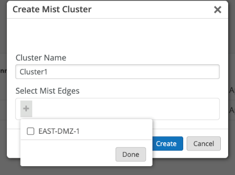
If you add multiple Mist Edge devices to a single cluster, you form an Active-Active configuration for all the devices in that cluster. Mist performs best-effort load balancing among the APs connected to that cluster. In the event one of the Mist Edge devices in the cluster goes down, the APs will failover to the other devices in that cluster. If you require an Active-Standby setup, create a second cluster for the Mist Edge device(s) you want to be on standby. In the event the Primary Cluster devices go down, the AP(s) will fail over to the Secondary Cluster device(s). You designate ca Mist Edge cluster as primary or secondary in the Mist Tunnels section of the Mist Edges page.
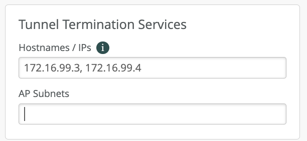
- Set Addresses for Tunnel Termination Services:
- From the left-nav menu, go to Mist Edges and click Create Cluster above the Mist Edge Cluster section. If you already have a cluster defined, you can simply click on its name.
- On the Cluster configuration page, locate the Tunnel Termination Services configuration block. Specify the Hostname or IP address. Use the same address or hostname that you configured for the Mist Edge Tunnel IP. If your cluster contains multiple Mist Edge devices, you must enter the IP addresses or hostnames of all cluster members as a comma-separated list.
- Click Save when finished.
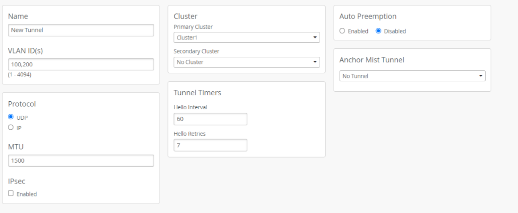
- Setup
Tunnel (Org-Level)
- From the left-nav menu, Go to Mist Edges and click Create Tunnel
above the Mist Tunnels section.

- On the Mist Tunnel configuration page, enter all user VLAN IDs that you want to extend from your corporate network, through the Mist Edge device(s), to the APs. You can enter Multiple VLAN IDs as a comma-separated list.
- In the Cluster block, assign the tunnel to the Mist Edge Cluster(s) you created
earlier. If you have only configured one cluster, set it as the primary cluster.
Otherwise, select the Primary and Secondary Cluster for this tunnel from
the appropriate pull-down list. Leave the rest of the settings on this page in their
default settings.
- From the left-nav menu, Go to Mist Edges and click Create Tunnel
above the Mist Tunnels section.
For additional details about the settings on this page, see: Failover Tunnel Timers, Auto Preemption, and Anchor Tunnel.
- Configure and prepare the WLAN
As illustrated in the previous chapter on how to create ORG-level WLANs, we follow all the recommendations and in addition we add the tunnel-related setup.
- Navigate to Organization > Wireless > WLAN Templates and create a new WLAN.
- In the Security block, select the following settings
- In the VLAN block, select Tagged. Mist APs only tunnel WLAN traffic configured with a tagged VLAN.
- For the VLAN ID, specify the desired VLAN(s). Use VLAN IDs from the list you defined in the Mist Edge tunnel configuration.
- The VLANs you configure here are tunneled by the AP through the Mist Edge.
- In the Custom Forwarding block, enable (check) Custom Forwarding to Mist, then select the appropriate tunnel service.
Location Services & Asset Visibility (Optional)
The Location Services & Asset Visibility section, while optional, unlocks powerful capabilities for enterprises leveraging Juniper Mist Access Points with integrated Virtual Bluetooth® Low Energy (vBLE) technology. This involves enabling the vBLE services on the deployed APs within the Mist Cloud. Once activated, IT administrators can configure precise location zones and upload detailed floor maps, allowing for highly accurate indoor positioning. This capability supports various applications, from providing real-time indoor navigation and wayfinding for users to enabling robust asset tracking for critical equipment. By integrating with asset tracking tags or mobile applications, organizations can gain valuable insights into the movement and location of resources, optimizing operations and enhancing efficiency within their physical spaces.
