Appendix: Day-0 Plan
Building a Virtual Chassis
Virtual Chassis Overview (Juniper Mist)
The Virtual Chassis technology enables you to connect multiple individual switches together to form one logical unit and to manage them as a single unit. You can configure and manage a Virtual Chassis using the Juniper Mist™ portal. The switches you add to a Virtual Chassis are called members. In a Virtual Chassis setup, VCPs connect the member switches and are responsible for passing the data and control traffic between member switches.
A Virtual Chassis helps you mitigate the risk of loops. It also eliminates the need for legacy redundancy protocols such as spanning-tree protocols (STPs) and Virtual Router Redundancy Protocol (VRRP). In core and distribution deployments, you can connect to the Virtual Chassis using link aggregation group (LAG) uplinks. These uplinks ensure that the member switches in a Virtual Chassis have device-level redundancy.
A Virtual Chassis can include from two to ten switches. Such a physical configuration can provide better resilience if a member switch goes down. One possible disadvantage of combining several switches into a Virtual Chassis is that this configuration requires more space and power than a single device requires.
Link to video: Virtual Chassis Overview
You can create a Virtual Chassis using the Form Virtual Chassis option on the portal. The Form Virtual Chassis option applies only to the Juniper Networks® EX4650 Switches, Juniper Networks® QFX5120 Switches, and EX2300 Switches, as these switches don't have dedicated VCPs. This option is not available to the Juniper Networks® EX4100-F Switch, Juniper Networks® EX4300 Switch, Juniper Networks® EX4600 Switch, EX3400, EX4100, and EX4400 Switches as they come with dedicated VCPs.
Table 1 shows the switch models along with the maximum number of member switches allowed in a Virtual Chassis configuration.
| Switch Model | Maximum Number of Members |
|---|---|
| EX2300 | 4 |
| EX4650 | 4 |
| EX3400 | 10 |
| EX4000 | 6 |
| EX4100 | 10 |
| EX4100-F | 10 |
| EX4100-H | 6 |
| EX4300 | 10 |
| EX4400 | 10 |
| EX4400-24X | 10 |
| EX4600 | 10 |
| QFX5120-32C,QFX5120-48T, QFX5120-48Y | 2 |
| QFX5120-48YM | 4 |
| QFX5110 | 10 |
Juniper Mist supports only preprovisioned Virtual Chassis configuration. It doesn't support non-provisioned configuration. The preprovisioned configuration enables the deterministic control of the roles and member IDs assigned to the member switches when creating and managing a Virtual Chassis. The preprovisioned configuration distinguishes member switches by associating their serial numbers with the member ID.
For more information, see Virtual Chassis Overview for Switches.
Mixed and Non-Mixed Virtual Chassis
A Virtual Chassis that includes switches of the same model can operate as a non-mixed Virtual Chassis. However, a Virtual Chassis that includes different models of the same switch (for example, two or more types of EX Series switches) must operate in mixed mode because of architecture differences between the different switch models.
| Allowed Routing Engine Members | Allowed Linecard Members |
|---|---|
| EX4300 | EX4300 and EX4600 |
| EX4300-48MP | EX4300-48MP and EX4300 (excludes EX4600) |
| EX4600 | EX4600 and EX4300 (excludes EX4300-48MP) |
For more information about the combination of switches that a mixed or a non-mixed Virtual Chassis configuration supports, see Understanding Mixed EX Series and QFX Series Virtual Chassis.
Design Considerations for Virtual Chassis
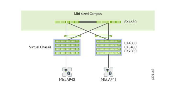
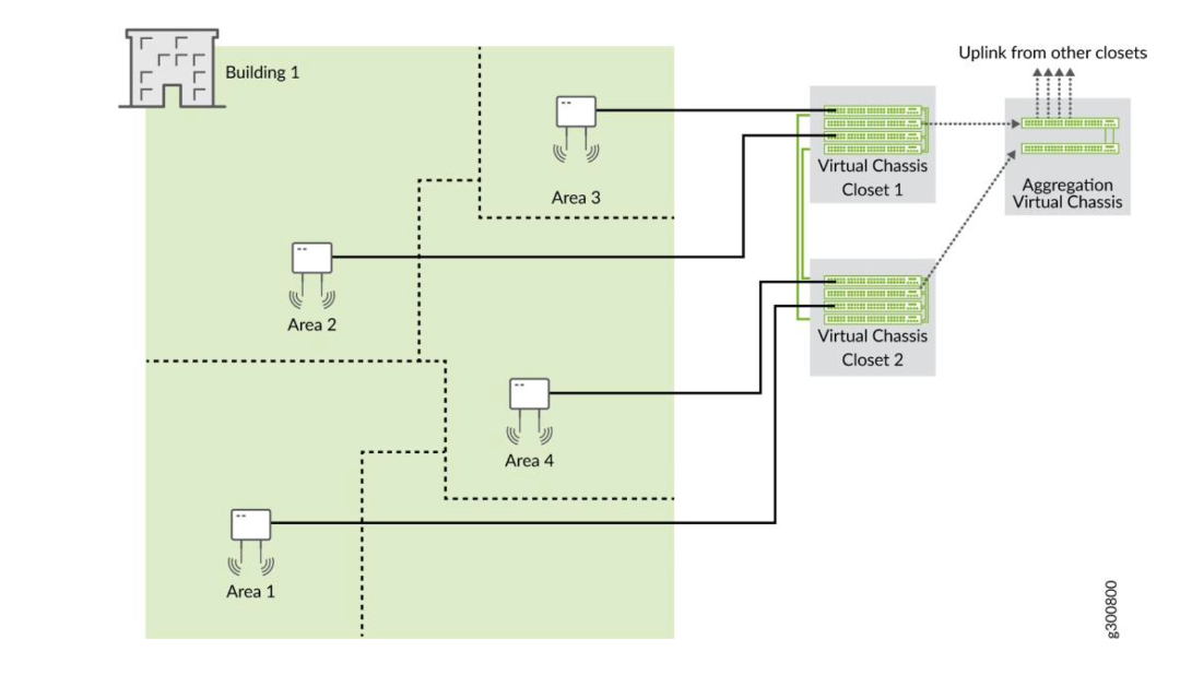
We recommend that you physically distribute your Juniper access points across a floor in the network operations center (NOC) so that they connect to multiple switches in a Virtual Chassis. Doing so provides better redundancy and is a more robust design for handling power supply-related hardware failure.
For example, let’s say you want to deploy a solution that includes 96 ports. The two main options for doing so are:
- Use two EX4300-48P Switches, with one switch serving as the primary and one as backup. The advantages here are a compact footprint and cost effectiveness. The main disadvantage is that the loss of one switch can impact 50 percent of your users.
- Use four EX4300-24P Switches, with one switch serving as the primary, one as backup, and two switches serving as line cards. The advantages here are higher availability (the loss of one switch only affects 25 percent of users), and the fact that uplinks are not affected by a switch failure (provided that the failed switch did not include any uplinks). The main disadvantage is that you need more space, power, and cost to support the equipment. Regardless of the options you go with, if you do plan to leverage one or more Virtual Chassis in your deployment, we recommend that you configure the primary and backup switches in the Virtual Chassis so that they are in different physical locations. The member devices of the Virtual Chassis should likewise be distributed so that no more than half are dependent on the same power supply or other single point of failure, and they should be evenly spaced by a member hop in the Virtual Chassis.
Workflow for VC Formation With Mist for EX3400, EX4000, EX4100, EX4100-F, EX4100-H, EX4300, EX4400 and EX4600 Switches
The EX3400, EX4000, EX4100, EX4100-F, EX4100-H, EX4300, and EX4400 Switches come with dedicated VCPs. A dedicated VCPs can be either a 100Gbit/s port on the back of the switch or a dedicated 10Gbit/s port on the front of the switch depending on the switch model. To create a Virtual Chassis using these switches, you only need to connect them to each other using VCPs. The Form Virtual Chassis option on the Switches page on the Juniper Mist portal is not applicable to these switches. However, once a Virtual Chassis is created with these switches, you can use the Modify Virtual Chassis option on the switch details page to modify and manage the Virtual Chassis. The Virtual Chassis workflow for these switches involves the following two steps:
- Virtual Chassis formation by connecting the switches using the dedicated VCPs and powering on them.
- (Optional but highly recommended) Preprovisioning the Virtual Chassis using the Modify Virtual Chassis option on the Juniper Mist portal. Juniper Mist supports only the preprovisioned Virtual Chassis configuration. The preprovisioned configuration specifies the chassis serial number, member ID, and role for both member switches in the Virtual Chassis. When a new member router joins the Virtual Chassis, Junos OS compares its serial number against the values specified in the preprovisioned configuration. Preprovisioning prevents any accidental role assignments, or the accidental addition of a new member to the Virtual Chassis. Each role, member ID, addition or removal of members, is under the control of the configuration.
Juniper Mist automatically upgrades a Virtual Chassis linecard member if it is running a Junos OS version different from that of the primary member. The linecard member will be upgraded to the same version as the primary member if the following conditions are met:
-
The switch must form a Virtual Chassis with three or more members—that is, a primary, a backup, and a linecard member.
-
The Junos OS version on the linecard member is different from that on the primary member.
-
The linecard member must be in Inactive state. Note that a linecard member will be upgraded only if it is inactive and running a clearly different Junos OS version. Minor version differences, such as different spin numbers, will not trigger an upgrade.
-
Only the Junos OS versions listed on the Juniper Mist portal are available for upgrade.
In addition to creating a Virtual Chassis, you can renumber, replace, or add a member to an existing Virtual Chassis, by using the Modify Virtual Chassis option on the Switch Details page.
The Modify Virtual Chassis option is available for switches that have the configuration management enabled in Juniper Mist.
You can configure the Virtual Chassis in mixed mode or non-mixed mode. A Virtual Chassis that includes switches of the same model operates as a non-mixed Virtual Chassis. However, a Virtual Chassis that includes different models of the same switch operates in mixed mode because of architecture differences between the different switch models. For more information, see Mixed and Non-Mixed Virtual Chassis.
To configure a Virtual Chassis using EX3400, EX4000, EX4100, EX4100-F, EX4100-H, EX4300, or EX4400 Switches:
- Ensure that all the switches that you want to include in the Virtual Chassis are onboarded to the Juniper Mist cloud and assigned to the same site. To onboard a new switch (greenfield deployment), see Onboard Switches to Mist Cloud. To onboard an existing switch (brownfield deployment), see Onboard a Brownfield Switch.
- Power off the switches that you want to include in the Virtual Chassis.
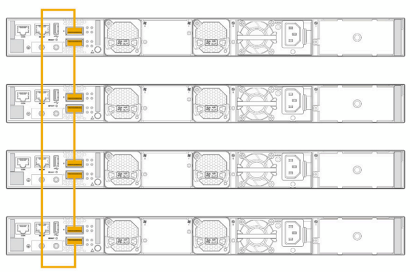
- Connect the switches to each other using the dedicated VCPs,
preferably in a full ring topology, as shown below. The following
is a sample image. The location of the VCPs will vary depending on
the switch models.
Figure 3: Virtual Chassis VCP connection as Ring
- Power on the switches.
- Wait for the MST LED on the primary and backup switches to come
up. The LED appears solid on the primary switch. On the backup
switch, the LED stays in a blinking state.Note:
The MST LED remains off on the switches elected as the linecard members in a Virtual Chassis.
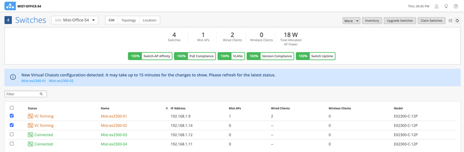
- A Virtual Chassis is now physically formed but not
preprovisioned.
Connect the Virtual Chassis to the Juniper Mist cloud by connecting the uplink port on the primary switch to the upstream switch.
We recommend connecting the uplink port only after the Virtual Chassis has formed. Wait for the MST LEDs to come up (LED appears solid on the primary member and blinking on the backup member), then connect the uplink ports on those members.
This step initiates a ZTP process on the Virtual Chassis and connects it to the Juniper Mist cloud.
After a Virtual Chassis connects to the Juniper Mist cloud for the first time, it may take 5 to 10 minutes for the Virtual Chassis stats to appear on the Juniper Mist cloud for all the members.
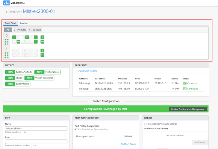
- Click Switches > Switch Name to go to the
Virtual Chassis page (the switch details page) to verify the
details.
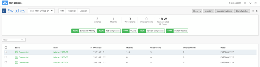
The switches appear as a single Virtual Chassis as shown below:
Figure 4: Virtual Chassis in Mist GUI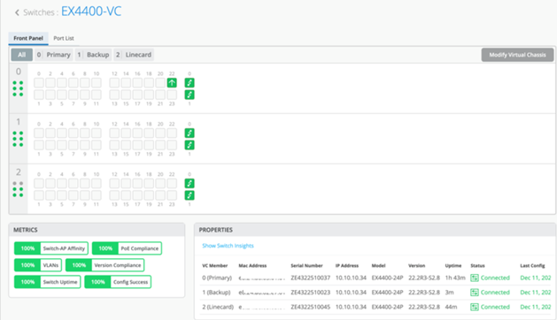
- After the Virtual Chassis is connected to the Juniper Mist
cloud, preprovision it. Preprovisioning allows users to define the
roles and renumber appropriately. To preprovision the Virtual
Chassis, follow the steps below:
- On the switch details page, click Modify Virtual
Chassis.
The Modify Virtual Chassis page appears.
- On the Modify Virtual Chassis page, click Preprovision Virtual Chassis. See a sample Modify Virtual Chassis page below:
- On the switch details page, click Modify Virtual
Chassis.
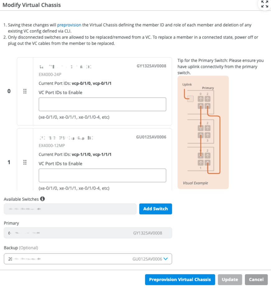
This step pushes the preprovisioned Virtual Chassis configuration to the device and overwrites the old autoprovision Virtual Chassis configuration pushed to the device during the ZTP process. This option assumes the current positioning of the members and preprovisions them as is.
If you make any changes on the Modify Virtual Chassis page, such as moving the members around or adding or removing members, the Preprovision Virtual Chassis button is disabled and the Update button is enabled. In this case, click the Update button to effect the changes made and preprovision the Virtual Chassis.
All configurations are pushed instantly after you preprovision the Virtual Chassis. The stats could take up to 15 minutes to appear on the Juniper Mist dashboard.
Workflow for Virtual Chassis Formation With Juniper Mist for EX2300, EX4650 and QFX5120
Virtual Chassis formation on the following EX Series Switches cannot be executed without preprovisioning. You may need to enable this in a lab or staging environment where you have proper access to the Juniper Mist cloud managing the devices so that they appear on the Inventory page. This must be done before you can execute the Virtual Chassis creation.
The EX2300, EX4650, and QFX5120 Switches do not form a Virtual Chassis by default, as these switches don’t have dedicated VCPs. Therefore, to create a Virtual Chassis with these switches, you need to use the Form Virtual Chassis option on the Juniper Mist™ portal. The Form Virtual Chassis option applies only to the EX2300, EX4650, and QFX5120 switches. This workflow creates a preprovisioned Virtual Chassis configuration. Juniper Mist supports only the preprovisioned Virtual Chassis configuration.
The procedure to configure a Virtual Chassis using the EX3400, EX4000, EX4100, EX4100-F, EX4100-H, EX4300, or EX4400 switches is different, as those switches have dedicated VCPs. For more information, see Workflow for VC formation with Mist for EX3400, EX4000, EX4100, EX4100-F, EX4100-H, EX4300, EX4400 & EX4600.
To configure a Virtual Chassis using EX2300, EX4650, or QFX5120 switches:
- Connect the switches to the Juniper Mist cloud. Ensure that you have an uplink connection directly to the switch.
- Ensure that all the switches that you want to include in the Virtual Chassis are onboarded to the Juniper Mist cloud and assigned to the same site. Also, ensure that configuration management is enabled on the switches.
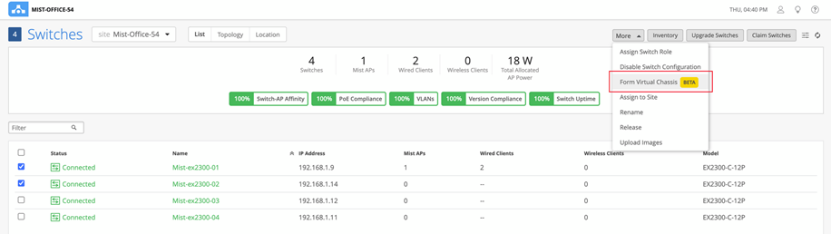
- Click the Switches tab on the left to navigate to the Switches page.
- Select the switches that you want to include in the Virtual
Chassis.
An EX2300 switch variant can form a Virtual Chassis with any EX2300 switch variants. An EX4650 variant switch can form a Virtual Chassis with any EX4650 switch variants. A QFX5120 switch variant can form a Virtual Chassis only with the same QFX5120 switch variant. Therefore, the Form Virtual Chassis option is available only if you select the right switch models for a Virtual Chassis.
- Click More > Form Virtual Chassis.
Figure 6: Form Virtual Chassis
 Note:
Note:You can see the Form Virtual Chassis option only if:The selected switches are running the same Junos OS version and have the configuration management option enabled.All the selected switch models are supported by the Virtual Chassis.
You can also create Virtual Chassis from the switch details page by using the Utilities > Form Virtual Chassis option.
The Form Virtual Chassis window appears, as shown in the following example.
Figure 7: Utilities option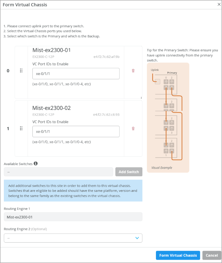 Note:
Note:This example shows two switches included in the Virtual Chassis. A Virtual Chassis device created using EX2300 or EX4650 switches supports up to 4 switches. All switches, except those assigned Routing Engine roles, function as linecard members.
- On the Form Virtual Chassis window, specify the following:
- Port IDs for the switches. These are IDs for the VCPs. This window displays all the switches you selected from the Switches page.
- The Routing Engine 1 switch. The switch that you selected first is shown as the Routing Engine 1 switch by default. You can modify that.
- The Routing Engine 2 switch. This
configuration is optional. If you don't select a switch to function
in the Routing Engine 2 role, Mist assigns the linecard role to
that switch.Note:
Juniper Mist automatically upgrades a Virtual Chassis linecard member if it is running a Junos OS version different from that of the primary member. The linecard member will be upgraded to the same version as the primary member if the following conditions are met:The switch must form a Virtual Chassis with three or more members—that is, a primary, a backup, and a linecard member.The Junos OS version on the linecard member is different from that on the primary member.The linecard member must be in Inactive state. Note that a linecard member will be upgraded only if it is inactive and running a clearly different Junos OS version. Minor differences, such as different spin numbers, will not trigger an upgrade.Only the Junos OS versions listed on the Juniper Mist portal are available for upgrade.
This operation converts the ports to VCPs and also preprovisions the Virtual Chassis.
- Click Form Virtual Chassis and wait for the
Virtual Chassis to be created.
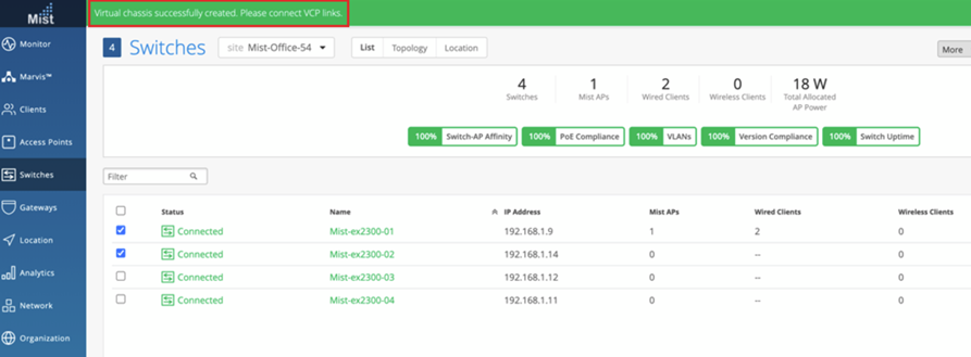
The Switches page shows a message indicating that you must connect the switches to each other using the VCPs.
- Connect the switches to each other using the configured VCPs.
When the Virtual Chassis formation is in progress, the Switches page shows the switch status as VC forming.
After the Virtual Chassis formation is successful, the Switches page displays only one entry for the Virtual Chassis with the name of the primary switch. However, the Mist APs column displays one AP for each Virtual Chassis member in a comma-separated format.
The switch details page displays the front panel of all the Virtual Chassis members.
 Note:
Note:Once the Virtual Chassis is formed, if you need only one uplink to the Virtual Chassis, maintain the uplink to the primary switch and remove uplinks from the other switches.
You can use the Modify Virtual Chassis option on the switch details page to renumber and replace Virtual Chassis members and add members to a Virtual Chassis connected to the Juniper Mist cloud. For more information, see Manage a Virtual Chassis Using Mist (Add, Delete, Replace, and Modify Members) .
Workflow for VC formation With Juniper Mist for EX4400-24X
Virtual Chassis formation on the following EX Series Switches cannot be executed without preprovisioning. You may need to enable this in a lab or staging environment where you have proper access to the Juniper Mist cloud managing the devices so that they appear on the Inventory page. For EX4400-24X switches, plan to have serial console access when preprovisioning the Virtual Chassis.
- Unbox and power on the EX4400-24X switches.
- Cloud reachability — Connect the 10GbE front panel ports or plug in a relevant uplink module on the EX4400-24X from each member of the Virtual Chassis to each of the upstream device(s) such as the WAN router and make sure the links come up as connected and able to reach the Juniper Mist cloud.
- Onboard the switch on the Juniper Mist dashboard:
- Claim method (Preferred): Please review the chapter “Activating a Greenfield Switch via claim and ZTP-based installation” below using QR-Code and Mist App / Mist dashboard.
- Adopt method: Please review the chapter “Activating a Brownfield Switch via Adoption Code-Based Installation” below.
- When using the claim method, the devices should appear in the
Inventory of the Juniper Mist cloud automatically as part of the
process. Using the adopt method, the switches may appear
immediately or after the Virtual Chassis has been formed.
The steps below detail forming a Virtual Chassis from the two EX4400-24X switches as an example:
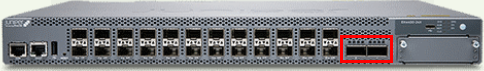
- Connect the VCPs on EX4400-24X using DAC Cables —
40G/100G. The VCPs are located on the front panel on the EX4400-24X
(as indicated in the figure below) and only support the HGoE
protocol for Virtual Chassis formation.
- Using either remote console or a serial console cable connected directly to the first
switch that will become the primary switch of your Virtual Chassis, login to the Junos OS
CLI and enter the following command:
request virtual-chassis mode hgoe <reboot> - This CLI command is needed to convert the two front panel ports
on the EX4400-24X switches from network ports to VCPs to enable
Virtual Chassis formation. See an example in the figure below.
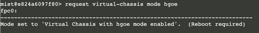
- Make sure the switch reboots now.
- Repeat the command on your backup switch followed by a reboot. Also repeat the command and reboot any optional linecard switches.
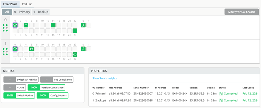
- Once the devices come up after the reboot, they should be in
Virtual Chassis mode and seen as a single device on the Juniper
Mist dashboard:
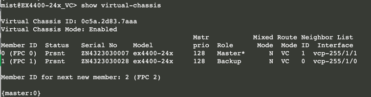
- OPTIONAL: Check the Virtual Chassis state using remote shell as shown in the figure below:
How Does an EX Series Switch Connect to the Juniper Mist Cloud to Get Managed?
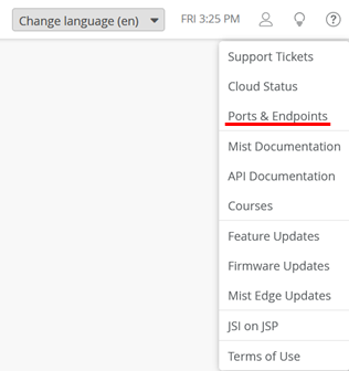
When an EX Series Switch must be managed by the Juniper Mist cloud, it must have a way to exchange data with the nearest reachable Juniper Mist cloud. You can’t use an EX Series Switch in air-gapped environments that do not provide Internet access. Should there be a firewall between the EX Series Switch and the Juniper Mist cloud, please check the link in your Mist account for “Ports & Endpoints” to configure the firewall to allow this traffic.
To avoid needing to use a console connection to pre-stage the device to apply a configuration, the switch should get a DHCP lease from the local network like any other wired or wireless client. Typically, the local WAN router runs a DHCP server configured to provide DHCP leases and access towards the Juniper Mist cloud for the attached switch.
Below, we show the factory default configuration that is expected to be on the switch when powering it on for the first time.
root@access1> edit
root@access1# load factory-default
warning: activating factory configuration
.
root@access1# show
system {
.
    phone-home {
        server https://redirect.juniper.net;
        rfc-compliant;
    }
    ## Warning: missing mandatory statement(s): 'root-authentication'
}
.
interfaces {
    ge-0/0/0 {
        unit 0 {
            family ethernet-switching {
                storm-control default;
            }
        }
    }
.
# we skipped showing the configuration of the other revenue interfaces
.
    irb {
        unit 0 {
            family inet {
                dhcp;
            }
        }
    }
    vme {
        unit 0 {
            family inet {
                dhcp;
            }
        }
    }
}
forwarding-options {
    storm-control-profiles default {
        all;
    }
}
protocols {
    lldp {
        interface all;
    }
    lldp-med {
        interface all;
    }
    igmp-snooping {
        vlan default;
    }
    rstp {
        interface all;
    }
}
poe {
    interface all;
}
vlans {
    default {
        vlan-id 1;
        l3-interface irb.0;
    }
}
In its factory default configuration, the switch is set to obtain a DHCP lease through various interfaces, install a default route, and attempt to connect to the Juniper Mist cloud for management. The switch automatically initiates communication with the Juniper Mist cloud, operating under the assumption that source NAT is applied somewhere along the network path to the cloud. With the default DHCP lease obtained, the switch is managed by two major methods of operation:
- The DHCP lease can be obtained by the dedicated out-of-band management port (may be labeled differently on the QFX Series and EX9200 line of Switches). This port is referred to as “me0” in Junos OS and the DHCP lease will be assigned to the virtual interface called “vme” (it’s referred to as “fxp0” on the EX9200 line of Switches). The usage of dedicated out-of-band management ports is designed for and typically used by campus fabric setups.
- The DHCP lease can be obtained by any regular revenue port on the switch. The factory-default configuration configures a native default VLAN on all revenue ports and maps that VLAN into the integrated routing and bridging (IRB) interface called “irb.0”. The DHCP lease is then assigned to this virtual interface. All other VLANs are assumed to use the same interface as trunked VLANs with IEEE 802.1q tags assigned. This in-band management method is very popular in branch deployments as you do not need extra cables just to manage the switch itself. Instead, you multiplex the upstream traffic into the same link and separate by means of regular VLANs.
A standalone switch for the recommended in-band management method can be attached to the WAN router via:
- A single link which is not redundant. The native VLAN over which the switch is managed from the Juniper Mist cloud is there as an initial link where the WAN router side might just be an access VLAN when starting. Over time you can change the two sides without losing the ability to manage the switch as long as you have a VLAN natively configured that continues to have the managed switch providing connection towards the Juniper Mist cloud.
- Multiple links that are redundant. It’s assumed in this case that both sides are able
to configure IEEE 802.ad link aggregation and active LACP to detect outages of any
configured link. As the link aggregation is not configured initially on the EX Series
Switch, you must first ensure that it is able to get a successful connection towards the
Juniper Mist cloud and then reconfigure the links as a LAG with active LACP. There are
multiple options of how you can achieve this which are explained in the next chapter
“Best practices when using Link Aggregation on
the uplink Interfaces”.Figure 8: Switch In-Band Management
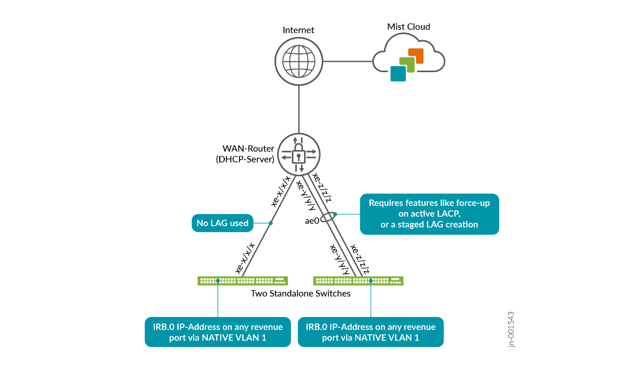
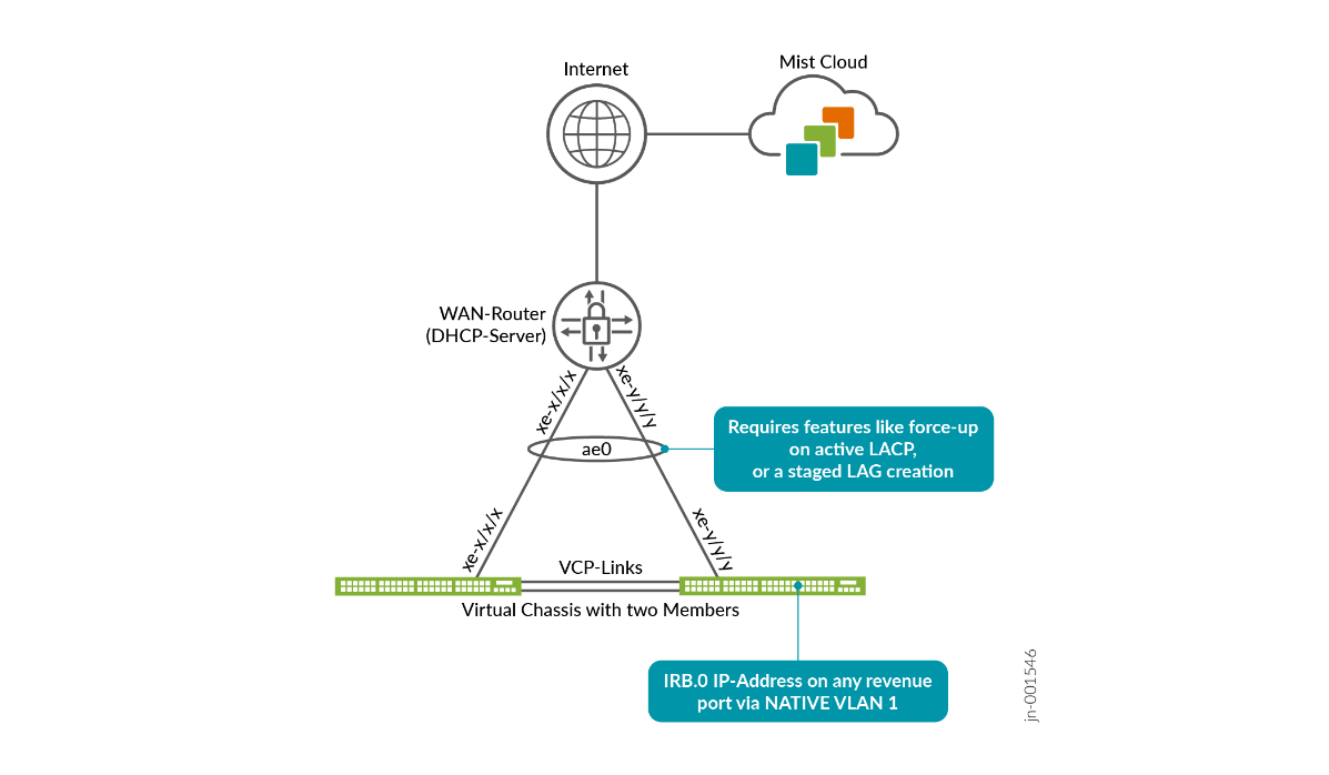
For a Virtual Chassis that uses in-band management, we recommend avoiding relying on a single uplink, even if it is technically supported. Instead, use multiple uplinks combined into a LAG with active LACP enabled. Ideally, each uplink should be connected to a different member switch within the Virtual Chassis, as illustrated below.
Since link aggregation is not configured by default, you must first ensure that the Virtual Chassis can successfully connect to the Juniper Mist cloud before reconfiguring the uplinks into a LAG with active LACP. Several methods can be used to accomplish this, which are described in the next chapter, Best practices when using Link Aggregation on the uplink Interfaces.
root@EX3400> show interfaces terse
Interface               Admin Link Proto    Local                 Remote
ge-0/0/0                up    down
ge-0/0/0.0              up    down eth-switch
ge-0/0/1                up    up
ge-0/0/1.0              up    up   eth-switch
ge-0/0/2                up    up
ge-0/0/2.0              up    up   eth-switch
ge-0/0/3                up    up
ge-0/0/3.0              up    up   eth-switch
.
irb                     up    up
irb.0                   up    up   inet     10.33.33.11/24
.
vme                     up    up
vme.0                   up    up   inet
.
.
root@EX3400> show arp
MAC Address       Address         Name                      Interface               Flags
ee:38:73:9a:d4:a5 10.33.33.1      10.33.33.1                irb.0 [ge-0/0/1.0]      none
.
root@EX3400> show route
.
inet.0: 3 destinations, 3 routes (3 active, 0 holddown, 0 hidden)
Limit/Threshold: 32768/32768 destinations
+ = Active Route, - = Last Active, * = Both
0.0.0.0/0          *[Access-internal/12] 00:01:34, metric 0
                    >  to 10.33.33.1 via irb.0
10.33.33.0/24      *[Direct/0] 00:01:35
                    >  via irb.0
10.33.33.11/32     *[Local/0] 00:01:35
                       Local via irb.0
Even though it is seldom used at the branch, one may still use out-of-band management. Here, we assume for cost reasons that a branch has an out-of-band management network set up only inside a single branch and not stretched across multiple branches.
A standalone switch, when using the out-of-band management method, can be attached to the WAN router using the switch’s dedicated management port. The WAN router then must provide the DHCP lease (one for each standalone switch, and one for each Virtual Chassis). Once the lease is obtained, the EX Series Switch can connect to the Juniper Mist cloud through the Internet and get managed by Mist. You have the same choice in terms of uplink to the WAN router:
- A single link which is not redundant. The management port is always configured as an access VLAN and the WAN router’s port configuration does not change over time. Hence, you are free to configure the uplink at any time between the WAN router and EX Series Switch without the fear of losing the ability to manage the switch.
- Multiple links that are redundant. It’s assumed in this case that both sides are able
to configure IEEE 802.ad link aggregation and active LACP to detect outages of any
configured link. The management port is always configured as an access VLAN, and the WAN
router’s port configuration does not change over time. Hence, you are free to configure
the uplink at any time between the WAN router and EX Series Switch without the fear of
losing the ability to manage the switch.Figure 10: Switch Out-of-Band Management
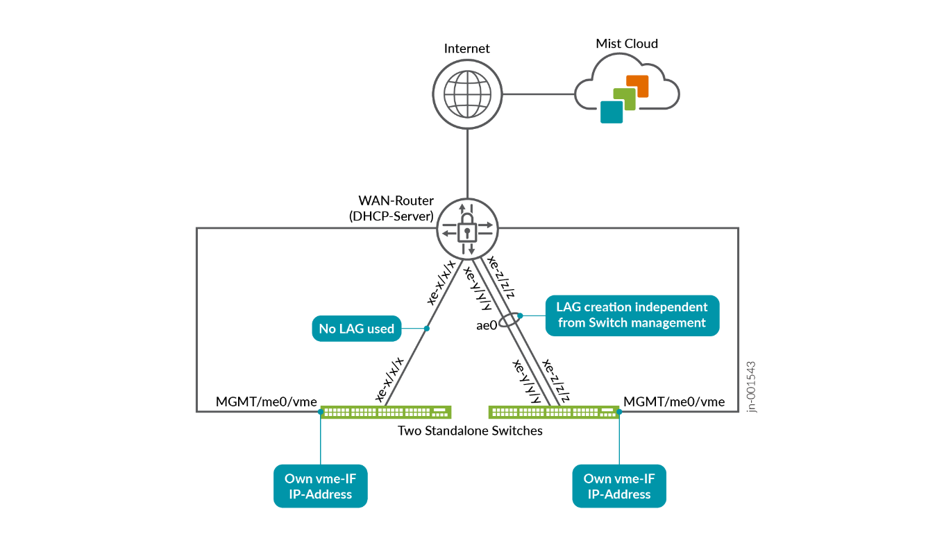
For a Virtual Chassis using in-band management, we recommend avoiding using a single uplink, even though it may be technically supported. Instead, use multiple uplinks combined into a LAG with active LACP enabled.
Unlike a standalone switch, a Virtual Chassis uses only one DHCP lease for the entire system, even when it includes up to ten member switches. This is achieved through the virtual “vme” interface, which holds the DHCP lease and can move between the Primary and Backup switches as needed. Member (linecard) switches within the Virtual Chassis do not obtain their own individual DHCP leases.
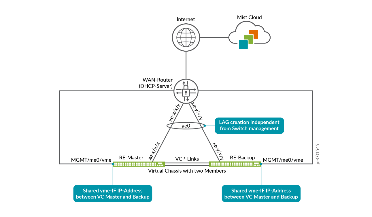
When using the switch management port to perform out-of-band management, the physical port is referred to as “me0” and a virtual port named “vme” is assigned the DHCP lease in order to connect to the Juniper Mist cloud as shown below.
root@access1> show interfaces terse
Interface               Admin Link Proto    Local                 Remote
.
.
me0                     up    up
me0.0                   up    up   eth-switch
.
.
vme                     up    up
vme.0                   up    up   inet     192.168.10.205/24
.
.
root@access1> show route
inet.0: xyz destinations, xyz routes (xyz active, 0 holddown, 0 hidden)
Limit/Threshold: 32768/32768 destinations
+ = Active Route, - = Last Active, * = Both
0.0.0.0/0          *[Access-internal/12] 1d 02:11:06, metric 0
                    >  to 192.168.10.1 via vme.0
.
.
192.168.10.0/24    *[Direct/0] 1d 02:11:06
                    >  via vme.0
192.168.10.205/32  *[Local/0] 1d 02:11:06
                       Local via vme.0
Independent of whichever method of managing the switch you are using, it is assumed that the DHCP lease also contains a DNS server assignment. Hence, ICMP pings using DNS resolution like the one shown below are expected to work.
root@access1> ping www.google.com inet
PING www.google.com (172.217.12.100): 56 data bytes
64 bytes from 172.217.12.100: icmp_seq=0 ttl=113 time=2.750 ms
64 bytes from 172.217.12.100: icmp_seq=1 ttl=113 time=2.711 ms
64 bytes from 172.217.12.100: icmp_seq=2 ttl=113 time=2.678 ms
Best practices When Using Link Aggregation on the Uplink Interfaces
When creating a LAG on an EX Series Switch, whether operating as a standalone device or part of a Virtual Chassis, two main benefits are gained:
- Link redundancy is provided, so if one or more links fail, the remaining links in the bundle continue to operate without interruption.
- Higher overall throughput is achieved when multiple traffic flows are present, as these flows can be distributed across all links in the bundle. The specific load-balancing method used depends on the configuration and is not discussed in detail here.
To maximize redundancy and achieve optimal throughput, we assume both sides support the following:
- Link aggregation according to IEEE 802.3ad.
- Dead link detection when both ends of the connection have active LACP configured on each link within the bundle. Simply creating a LAG without LACP and relying on the physical layer to detect link failure is not sufficient. For example, if a LAG includes two fiber links and one of them fails, one side might still detect its interface as physically “up,” even though communication is no longer bidirectional. Using a protocol like LACP provides continuous monitoring of link status, allowing the system to quickly identify failures and maintain proper operation. It also helps trigger rebalancing of the ECMP load distribution when network topology changes occur.
This isn’t a concern when using out-of-band management since the LAG link setup is independent from the device management connection to the Juniper Mist cloud. However, when using in-band management, you need to avoid losing the management connection to the switch when forming the LAG between the WAN router and the EX Series Switch. This is because when configuring active LACP for a particular side, there will be no communication on that link before the remote side has configured active LACP and exchanged LACP packets to unblock this link for communication. This leads to a kind of chicken and egg problem between the WAN router and attached EX Series Switch. You cannot have one side activating active LACP on the bundle without losing the other side. To overcome this problem, you have the following options:
- The recommended method is: Some devices (like the Juniper
Networks® SRX Series Firewalls) support special features like
the so called “force-up” feature. This relaxes the
strict active LACP checking on one link of the WAN router’s
bundle. Hence, the EX Series Switch can use this link to
communicate with the Juniper Mist cloud before the LAG is formed on
both sides. The following describes the workflow to set this up:
- On the WAN router, configure the entire LAG bundle with all member links. One member link is configured with the “force-up” feature.
- The EX Series Switch attach comes up initially. Communication to the Juniper Mist cloud will only be possible over the WAN router link which has the force-up option set.
- Now you can configure the LAG bundle on the EX Series Switch with all members included. As the WAN router already has a valid configuration, the entire LAG between the two should automatically come up.
- Once both sides have built the LAG with active LACP running on all member links, you can remove the “force-up” feature on the WAN router side.
- If such a “force-up” feature or similar is not supported by the WAN router, then
consider the next method when building the LAG:
- Configure the link bundle excluding one link on the EX Series Switch and let the Juniper Mist cloud push the configuration.
- Configure the link bundle excluding one opposite link on the WAN router and apply the configuration.
- Both devices should now build an LAG link with active LACP on both sides, with communication remaining on the single untouched link between the two.
- Now you can update the LAG bundle on the EX Series Switch with all members included. Device management is expected to now failover to the LAG bundle and continue.
- You can update the LAG bundle on the WAN router with all members included to reach the final state.
- The last alternative method is to pre-stage the LAG configuration on the EX Series
Switch. This will ensure the needed configuration is already there and the device is
already known to the Juniper Mist cloud.
- Pre-stage the device in a lab or staging environment before shipping it on-site. You may also use this opportunity to refresh the Junos OS firmware on the device.
- While on-site with proper instructions to the person performing the installation, consider doing out-of-band management for a short while until the LAG is configured.
The figure below shows the example configuration on an SRX as a WAN router utilizing the recommended “force-up” feature.
The methods that have been presented here for connecting a WAN router and a directly connected EX Series Switch works the same in respect to a larger topology with distribution and access switches. It can be used when you build the connection between the WAN router and distribution switch and then start deploying the access switches. The “force-up” feature is available on EX Series Switches so you can use it on the distribution switches when configuring the downlinks to the access switches.
Overview of the ZTP Process
The ZTP process described here is not to be mistaken with an older ZTP method that is described in documentation and that is also supported. That method always needs a local DHCP server that delivers special DHCP attributes within the DHCP lease to the local EX Series Switch to inform the switch where to fetch the initial configuration and other items (usually via TFTP). The ZTP method described here is free of such constraints. The local DHCP server just needs to provide regular IP address, gateway and DNS server information like that provided for any other wired or wireless client.
Once a cloud-ready switch is connected to the internet and powered on for the first time,
it triggers an onboard phone-home client (PHC) to get configuration updates from the
phone-home server (PHS) as shown in Figure 12. The default
behavior is for the PHC to connect to a redirect server, which then redirects it to a phone
home server where the switch can get the configuration or software image. This enables the
switch to obtain the most recent Junos OS configuration or software image securely and
automatically, with no intervention other than physically connecting the switch to the
network. Alternatively, you can configure the switch to use a DHCP server configured with
the necessary ZTP options to complete the ZTP process. To revert to the ZTP default, you
need to boot from factory default state (or you can issue the Junos OS request
system zeroize command to reset the configuration).
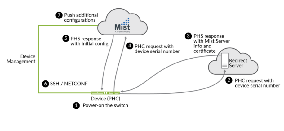
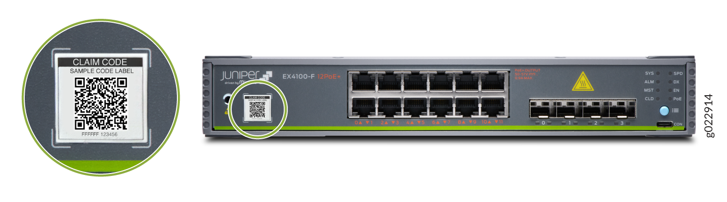
Juniper ZTP follows IETF RFC 8071 as a standards-based method. The switch must be “cloud-ready” to be able to perform this operation out of the box without any additional pre-configuration needed. The Juniper Networks® Cloud-Ready Switches come ready to install and manage using the portal at https://manage.mist.com. Your switch is cloud-ready if it has a QR claim code on the front or back panel.
The onboarding procedures described in this guide apply only to cloud-ready EX and QFX switches. See Juniper Mist Supported Hardware for a list of cloud-ready EX and QFX switches.
Switch Connectivity Towards the Juniper Mist Cloud
When a switch is managed by the Juniper Mist cloud, it must initiate a connection to the cloud in order to be controlled and configured remotely. This approach is necessary because the switch typically resides behind an enterprise firewall. In most environments, several switches may be located behind the same firewall, and requiring inbound connections from the cloud would force IT staff to manually configure port forwarding for each device.
- Instead, it is more efficient for the switch to establish the outbound connection to the Juniper Mist cloud. This allows standard source NAT on the enterprise firewall or broadband router to automatically permit the connection. Once the connection is active, all communication between the switch and the cloud—including configuration updates, commands, and monitoring data—is securely multiplexed through this single, bidirectional connection. Apply the device configuration through NETCONF pushed by Juniper Mist cloud.
- Collect interface statistics and log files from the device and upload them to Juniper Mist cloud.
- Allow a remote shell using Juniper Mist portal or Websocket.
- Issue Junos OS commands on the device.
- Trigger firmware update commands on the device.
Outbound SSH Towards Juniper Mist Cloud
The capability for Junos OS devices to initiate an outbound SSH connection to a cloud-based management system has been available for several years and is not a new feature. Originally, management through the Juniper Mist cloud involved sending event scripts to the device, which were then executed locally. This approach has since been replaced with a more advanced model.
Today, once the connection to the Juniper Mist cloud is established, the cloud deploys a PyAgent to the device. This agent handles management tasks directly and offers the following advantages over the previous event script method, providing greater flexibility, reliability, and efficiency in communication and configuration management:
- Push model
- Reduced CPU load when compared with event scripts
- Better WAN utilization
- Faster event framework
- Switch statistics collection interval is 180 seconds.
Outbound SSH utilizes a destination TCP connection towards port 2200 implemented in Juniper Mist cloud initiated by the switch.
A newer method exists that the switch can now also utilize. Read about CloudX below.
CloudX HTTPS Connectivity
Juniper CloudX, integrated natively into Junos OS, is an advanced architecture that ensures faster and secure communication between Juniper switches and the Juniper Mist cloud. It is responsible for creating a secure connection between the switch and the Juniper Mist cloud. CloudX-enabled switches can be monitored and managed by cloud services.
CloudX applies to both new and existing switches. It enables the new switches to communicate directly over HTTPS 443 when they are onboarded to Juniper Mist cloud using ZTP. With CloudX enabled, the existing switches that are connected to the Juniper Mist cloud over TCP port 2200 will have their connection switched to CloudX with no impact on the data plane. For switches to connect and communicate using CloudX over TCP 443, the following firewall port must be opened: jma-terminator.[xx].mist.com(TCP 443). The variable [xx] should be replaced by the environment name.

Benefits of CloudX:
- Keeps the data on the cloud up to date. Events are sent to the cloud every 10-15 seconds and stats are updated every 1-2 minutes.
- Leverages the Junos Telemetry Interface (JTI), which ensures asynchronous and faster communication by bypassing any polling from the cloud to the switch.
- Enables switches to connect to the cloud over HTTPS port 443, like Juniper APs. You do not need to open any non-standard ports on the firewall.
- Enables switches to communicate with the Juniper Mist cloud through a proxy server. You can statically define a proxy server or dynamically send proxy server details through DHCP option 43. For more information, see Connect a Switch to Mist Cloud via a Proxy Server Using CloudX.
- Offers packet capture for switches on the Juniper Mist cloud. You can initiate packet capture on a single switch port or a range of ports. You can leverage the on-demand packet capture feature in Mist to view transit traffic or control traffic. For more information, refer to Packet capture examples.
Availability of CloudX
The following table lists the platforms that support CloudX in different Junos OS releases. The table lists multiple Junos OS versions for each platform. Different models (variants) within each platform are also supported. So, the EX4100-F and EX4100-H variant of the EX4100 Series is also supported. We recommend that you upgrade the switch to a Junos suggested release for the CloudX support.
For CloudX to work, you must ensure that the firewall port towards jma-terminator.xx.mist.com is open and SSL encryption is disabled on the firewall (for more information, refer to Juniper Mist Firewall Ports and IP Addresses for Firewall Configuration). To check if your switch is communicating with Juniper Mist cloud by using CloudX, refer to the steps listed in Troubleshooting Juniper CloudX. If you still don't see CloudX enabled on your switch even after upgrading it to a supported Junos OS release, contact Juniper support.
| Platforms | Supported Junos OS Release | CloudX Availability |
|---|---|---|
| EX2300/EX3400 |
23.4R2-S4 and above 24.2R1-S2 and above |
Generally Available |
| EX4000 |
24.4R1 and above 24.4R1-S2 and above |
Generally Available |
| EX4400/EX4100 |
22.4R2-S1 and above 22.4R3 and above 23.4R2 and above 24.2R1 and above |
Generally Available |
| EX4650/QFX5120 |
23.4R2-S4 and above 24.2R1-S2 and above |
Generally Available |
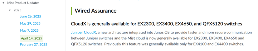
Since April 2025, CloudX is also automatically activated on EX2300, EX3400, EX4650 and QFX5120 switches as mentioned in the announcement below:
Additional changes when CloudX is used:
- While CloudX enables the ability to perform packet captures and send the results towards the Juniper Mist cloud, not all platforms support that ability in hardware. Presently, only the EX4000, EX4100 and EX4400 support packet captures.
- When CloudX is enabled, the way dynamic port configuration is maintained is changed. Please review When do we use Dynamic Port Profiles and when do we use a NAC Infrastructure? for more information.
Design a Switch Template
A key feature of switch management through the Juniper Mist cloud is the ability to use configuration templates and a hierarchical model to group the switches and make bulk updates. Templates provide uniformity and convenience, while the hierarchy (organization, site, and switch) provides both scale and granularity.
What templates, and the hierarchical model, means in practice is that you can create a template configuration and then apply those settings to all the devices in each group. When a conflict occurs, for example, when there are settings at both the site and organizational levels that apply to the same device, the narrower settings (in this case, the site hierarchy) override the broader settings defined at the organization level.
Individual switches, at the bottom of the hierarchy, can inherit all or part of the configuration defined at the organization level, and again at the site level. Of course, individual switches can also have their own unique configurations.
You can include individual CLI commands at any level of the hierarchy, which are then appended to all the switches in that group on an “AND” basis —that is, individual CLI settings are appended to the existing configuration (existing settings are not replaced).
We recommend that all switches in an organization be managed exclusively through the Juniper Mist cloud, and not from the device’s CLI.
The process of configuring a switch with Juniper Mist Wired Assurance involves two main steps: creating a switch configuration template and applying it to one or multiple sites. The configuration settings linked to a particular site will be applied to the switches within that site. This allows you to manage and apply consistent and standardized configurations across your network infrastructure, making the configuration process more efficient and streamlined.
For a quick overview of switch templates, watch the following video.
To configure a switch, you need to have a Super User role assigned to you. This role grants you the necessary permission to make changes and customize the switch settings. Other roles may just allow you to change a port or only to review a configuration without the ability to change it.
Create a Switch Configuration Template
Switch configuration templates make it easy to apply the same settings to switches across your sites. Whether it's one site or multiple sites, you can use the template to quickly configure new switches. When you assign a switch to a site, it automatically adopts the configuration from the associated template.
Configuration done on the switch through the Juniper Mist dashboard overrides any configuration done through the device CLI. The switch details page doesn’t display any configuration changes you make directly on the switch through the switch CLI.
To create a switch configuration template:
- Open the portal and click Organization > Switch Templates.
- Click Create Template, enter a name for the
template in the Template Name field, and then
click Create. The Switch Templates:
<Template Name> page appears.Note:
You have the flexibility to import the template settings from a JSON file instead of manually entering the information. To import the settings, click Import Template. To get a JSON file with the configuration settings that can be customized and imported, open an existing configuration template of your choice, and click Export.
- In the All Switches configuration section,
configure basic settings for the switches. Use the tips on the
screen to configure the settings.
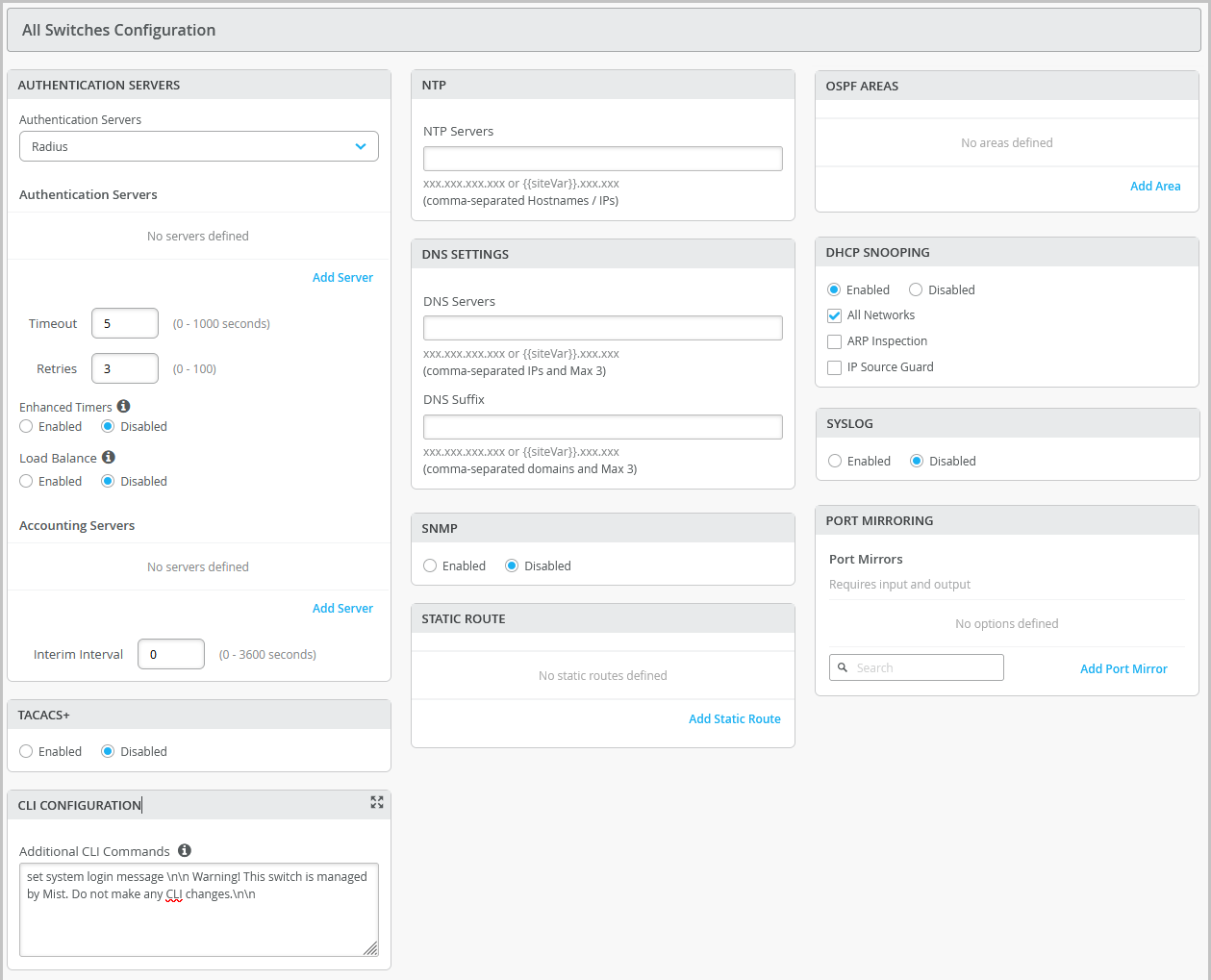
Table 4: All Switch Configuration Field Descriptions Field Description RADIUS Choose an authentication server for validating usernames and passwords, certificates, or other authentication factors provided by users.
- Mist Auth—Select this option if you want to configure Juniper Mist Access Assurance, a cloud-based authentication service from Mist, on your switch. For this option to work, you also need to use a port with dot1x or MAB authentication.
Note: Mist Auth on wired switches require Junos OS 20.4R3-S7 or above, 22.3R3 or above, 22.4R2 or above, or 23.1R1 or above.
To configure Juniper Mist Access Assurance features such as authentication policies, policy label, certificates, and identity providers, navigate to Organization > Access.
- RADIUS—Select this option to configure a RADIUS authentication server and an accounting server, for enabling dot1x port authentication at the switch level. For the dot1x port authentication to work, you also need to create a port profile that uses dot1x authentication, and you must assign that profile to a port on the switch.
The default port numbers are:
- port 1812 for the authentication server
- port 1813 for the accounting server
Note:If you want to set up dot1x authentication for switch management access (for the switch CLI login), you need to include the following CLI commands in the Additional CLI Commands section in the template:
set system authentication-order
                        radius
set system radius-server <radius-server-IP> port 1812set system radius-server <radius-server-IP> secret <secret-code>set system radius-server <radius-server-IP> source-address <radius-Source-IP>TACACS+ Configure TACACS+ for centralized user authentication on network devices. Additionally, you can enable TACACS+ accounting on the device to gather statistical data about user logins and logouts on a LAN and send this data to a TACACS+ accounting server.
The port range supported for TACACS+ and accounting servers is 1 to 65535.
NTP Specify the IP address or hostname of the Network Time Protocol (NTP) server. NTP is used to synchronize the clocks of the switch and other hardware devices on the Internet. DNS SETTINGS Configure the domain name server (DNS) settings. You can configure up to three DNS IP addresses and suffixes in comma separated format. SNMP Configure Simple Network Management Protocol (SNMP) on the switch to support network management and monitoring. You can configure the SNMPv2 or SNMPv3. Here are the SNMP options that you can configure:
Options under SNMPv2 (V2)
- General—Specify the system's name, location, administrative contact information, and a brief description of the managed system. When using SNMPv2, you have the option to specify the source address for SNMP trap packets sent by the device. If you don't specify a source address, the address of the outgoing interface is used by default.
- Client—Define a list of SNMP clients. You can add multiple client lists. This configuration includes a name for the client list and IP addresses of the clients (in comma separated format). Each client list can have multiple clients. A client has a prefix with a /32 mask.
- Trap Group—Create a named group of hosts to receive the specified trap notifications. At least one trap group must be configured for SNMP traps to be sent. The configuration includes the following fields:
- Group Name—Specify a name for the trap group.
- Categories—Choose from the following list of categories. You can select multiple values as there are: authentication, chassis, configuration, link, remote-operations, routing, services, startup and vrrp-events
- Targets—Specify the target IP addresses. You can specify multiple targets.
- Version—Specify the version number of SNMP traps.
- Community—Define an SNMP community. An SNMP community is used to authorize SNMP clients by their source IP address. It also determines the accessibility and permissions (read-only or read-write) for specific MIB objects defined in a view. You can include a client list, authorization information, and a view in the community configuration.
- View (Applicable to both SNMPv2 and SNMPv3)—Define a MIB view to identify a group of MIB objects. Each object in the view shares a common object identifier (OID) prefix. MIB views allow an agent to have more control over access to specific branches and objects within its MIB tree. A view is made up of a name and a collection of SNMP OIDs, which can be explicitly included or excluded.
Options under SNMPv3 (V3)
- General—Specify the system's name, location, administrative contact information, and a brief description of the managed system. When using SNMPv2, configure an engine ID, which serves as a unique identifier for SNMPv3 entities.
- USM—Configure the user-based security model (USM) settings. This configuration includes a username, authentication type, and an encryption type. You can configure a local engine or a remote engine for USM. If you select a remote engine, specify an engine identifier in hexadecimal format. This ID is used to compute the security digest for authenticating and encrypting packets sent to a user on the remote host. If you specify the Local Engine option, the engine ID specified on the General tab is considered. If no engine ID is specified, local mist is configured as the default value.
- VACM—Define a view-based access control model (VACM). A VACM lets you set access privileges for a group. You can control access by filtering the MIB objects available to read, write, and notify operations using a predefined view (you must define the required views first from the Views tab). Each view can be associated with a specific security model (v1, v2c, or usm) and security level (authenticated, privacy, or none). You can also apply security settings (you have the option to use already defined USM settings here) to the access group from the Security to Group settings.
- Notify—Select SNMPv3 management targets for notifications and specify the notification type. To configure this, assign a name to the notification, choose the targets or tags that should receive the notifications, and indicate whether it should be a trap (unconfirmed) or an inform (confirmed) notification.
- Target—Configure the message processing and security parameters for sending notifications to a particular management target. You can also specify the target IP address here.
View (Applicable to both SNMPv2 and SNMPv3)—Define a MIB view to identify a group of MIB objects. Each object in the view shares a common object identifier (OID) prefix. MIB views allow an agent to have more control over access to specific branches and objects within its MIB tree. A view is made up of a name and a collection of SNMP OIDs, which can be explicitly included or excluded.
STATIC ROUTE Configure static routes. The switch uses static routes when:
- It doesn't have a route with a better (lower) preference value.
- It can't determine the route to a destination.
- It needs to forward packets that can't be routed.
Types of static routes supported:
- Subnet—Includes the IP addresses for the destination network and the next hop.
- Network—Includes a VLAN (containing a VLAN ID and a subnet) and the next hop IP address.
CLI CONFIGURATION For any additional settings that are not available in the template's GUI, you can still configure them using set CLI commands.
For instance, you can set up a custom login message to display a warning to users, advising them not to make any CLI changes directly on the switch. Here's an example of how you can do it:
set system login message
                        "\n\n Warning! This switch is managed by Mist. Do not make any CLI
                        changes."
To delete a CLI command that was already added, use the delete command, as shown in the following example:
delete system login message "\n\n Warning! This switch is managed by Mist. Do not make any CLI changes."Note:Ensure that you enter the complete CLI command for the configuration to be successful.
OSPF AREAS Define an Open Shortest Path First (OSPF) area, if required. OSPF is a link-state routing protocol used to determine the best path for forwarding IP packets within an IP network. OSPF divides a network into areas to improve scalability and control the flow of routing information. DHCP SNOOPING Enable the DHCP snooping option to monitor DHCP messages from untrusted devices connected to the switch. DHCP snooping creates a database to keep track of these messages. This helps prevent the acceptance of DHCPOFFER packets on untrusted ports, assuming they originate from unauthorized DHCP servers.
DHCP configuration has the following options:
- All Networks— Select the All Networks check box to enable DHCP snooping on all VLANs.
- Networks—If you want to enable DHCP snooping only on specific networks, click Add (+) in the Networks box and add the required VLANs.
- Address Resolution Protocol (ARP) Inspection—Enable this feature to block any man-in-the-middle attacks. ARP Inspection examines the source MAC address in ARP packets received on untrusted ports. It validates the address against the DHCP snooping database. If the source MAC address does not have a matching entry (IP-MAC binding) in the database, it drops the packets.
You can check ARP statistics by using the following CLI commands: show dhcp-security arp inspection statistics , and show log messages | match DAI .
The device logs the number of invalid ARP packets that it receives on each interface, along with the sender’s IP and MAC addresses. You can use these log messages to discover ARP spoofing on the network.
- IP Source Guard—IP source guard validates the source IP and MAC addresses received on untrusted ports against entries in the DHCP snooping database. If the source addresses do not have matching entries in the database, IP Source Guard discards the packet.
Note: IP Source Guard works only with single-supplicant 802.1X user authentication mode.
Note:
- If you have a DHCP server connected to an untrusted access port, DHCP won't function properly. In such cases, you may need to make adjustments to ensure that DHCP works as intended. By default, DHCP considers all trunk ports as trusted and all access ports as untrusted.
- You need to enable VLAN on the switch for the DHCP snooping configuration to take effect. So, you need to apply port profiles (described later in this document) to the ports.
A device with a static IP address might not have a matching MAC-IP binding in the DHCP snooping database, if you have connected the device to an untrusted port on the switch. To check the DHCP snooping database on your switch and view the bindings, use the CLI command show dhcp-security binding. This command will provide you with information about the DHCP bindings recorded in the snooping database.
Note: You need to enable this feature if you want to view the DHCP issues for the switch under the Successful Connect SLE metric.
SYSLOG Configure SYSLOG settings to set up how system log messages are handled. You can configure settings to send the system log messages to files, remote destinations, user terminals, or to the system console. Here are the configuration options available for SYSLOG settings:
- Files—Send log messages to a named file.
- Hosts—Send log messages to a remote location. This could be an IP address or hostname of a device that will be notified whenever those log messages are generated.
- Users—Notify a specific user of the log event.
- Console—Send log messages of a specified class and severity to the console. Log messages include priority information, which provide details about the facility and severity levels of the log messages.
- Archive—Define parameters for archiving log messages.
- General—Specify general information such as a time format, routing instance, and source address for the log messages.
PORT MIRRORING Configure port mirroring.
Port mirroring is the ability of a router to send a copy of a packet to an external host address or a packet analyzer for analysis. In the port mirroring configuration, you can specify the following:
- Input: The source (an interface or network) of the traffic to be monitored. Along with the input, you can specify whether you want Mist to monitor the ingress traffic or the egress traffic for an interface. If you want both ingress and egress traffic to be monitored, add two input entries for the same interface - one with the ingress flag and the other with the egress flag.
- Output: The destination interface to which you want to mirror the traffic. You cannot specify the same interface or network in both the input and output fields.
- In the Management section of the Switch
Template Configuration page, configure the following:
- Configuration Revert Timer—This feature helps restore connectivity between a switch and the Juniper Mist cloud if a configuration change causes the switch to lose connection. It automatically reverts the changes made by a user and reconnects to the cloud within a specified time duration. By default, this time duration is set to 10 minutes for EX Series Switches. You can specify a different time duration here.
- Root password—A plain-text password for the root-level user (whose username is root).
- Protection of Routing Engine—Enable this feature to ensure that the Routing Engine accepts traffic only from trusted systems. This configuration creates a stateless firewall filter that discards all traffic destined for the Routing Engine, except SSH and BGP protocol packets from specified trusted sources.
- In the Shared Elements section, configure the
following:
- In the Networks tile, click Add Network and configure the VLANs to be used in the port profiles. The settings include a Name, VLAN ID, and a Subnet.
- In the Port Profiles tile, choose a predefined port profile or click Add
Profile to create a new profile and assign a network to it. Port profiles
provide a way to automate provisioning of multiple switch interfaces. Use the tips on
the screen to configure the port profile settings.
Table 5 for tips about key fields in the port profile.
Note:This table does not include basic fields such as Name, Enabled, Disabled, Description, and so on.
Table 5: Port Profile Fields Field Description Mode Trunk—Trunk interfaces typically connect to other switches, APs, and routers on the LAN. In this mode, the interface can be in multiple VLANs and can multiplex traffic between different VLANs. Specify the Port Network, VoIP Network (if applicable), and Trunk Networks.
Access—Default mode. Access interfaces typically connect to network devices, such as PCs, printers, IP phones, and IP cameras. In this mode, the interface can be in a single VLAN only. Specify the Port Network and the VoIP Network (if applicable).
Use dot1x authentication Select this option to enable IEEE 802.1X authentication for Port-Based Network Access Control. 802.1X authentication is supported on interfaces that are members of private VLANs (PVLANs).
The following options are available if you enable dot1x authentication on a port:
Allow Multiple Supplicants—Select this option to allow multiple end devices to connect to the port. Each device is authenticated individually.
Dynamic VLAN—Specify dynamic VLANs that will be returned by the RADIUS server attribute 'tunnel-private-group-ID' or 'Egress-VLAN-Name'. This configuration enables a port to perform dynamic VLAN assignment.
MAC authentication—Select this option to enable MAC authentication for the port. When this option is selected, you can also specify an Authentication Protocol. If you specify a protocol, it must be used by supplicants to provide authentication credentials.
Use Guest Network—Select this option to use a guest network for authentication. Then select a Guest Network from the drop-down list.
Bypass authentication when server is down—If you select this option, clients can join the network without authentication if the server is down.
You need to also do the following for dot1x authentication to work:
Configure a RADIUS server for dot1x authentication from the Authentication Servers tile in the All Switches Configuration section of the template.
Assign a dot1x port profile to a switch port for the RADIUS configuration to be pushed to the switch. You can do this from the Port Config tab in the Select Switches Configuration section of the template.
MAC Limit Configure the maximum number of MAC addresses that can be dynamically learned by an interface. When the interface exceeds the configured MAC limit, it drops the frames. A MAC limit also results in a log entry.
The default value: 0
Supported range: 0 through 16383
PoE Enable the port to support power over Ethernet (PoE). STP Edge Configure the port as a Spanning Tree Protocol (STP) edge port, if you want to enable Bridge Protocol Data Unit (BPDU) guard on a port. This setting ensures that the port is treated as an edge port and guards against the reception of BPDUs, which are control messages in the STP. If you plug a non-edge device into a port configured with STP Edge, the port is disabled. In addition, the Switch Insights page generates a Port BPDU Blocked event. The Front Panel on the Switch Details will also display a BPDU Error for this port.
You can clear the port of the BPDU error by selecting the port on the Front Panel and then clicking Clear BPDU Errors.
You can also configure STP Edge at the switch level, from the Port Profile section on the switch details page.
QoS Enable Quality of Service (QoS) for the port to prioritize latency-sensitive traffic, such as voice, over other traffic on a port.
Note: For optimal results, it's important to enable Quality of Service (QoS) for both the downstream (incoming) and upstream (outgoing) traffic. This ensures that the network can effectively prioritize and manage traffic in both directions, leading to improved performance and better overall quality of service.
You have the option to override the QoS configuration on the WLAN settings page (Site > WLANs > <WLAN name>). To override the QoS configuration, select the Override QoS check box and choose a wireless access class. The downstream traffic (AP > client) gets marked with the override access class value specified. The override configuration doesn't support upstream traffic (client > AP).
Storm Control Enable storm control to monitor traffic levels and automatically drop broadcast, multicast, and unknown unicast packets when the traffic exceeds a traffic level (specified in percentage). This specified traffic level is known as the storm control level. This feature actively prevents packet proliferation and maintains the performance of the LAN. When you enable Storm Control, you can also choose to exclude broadcast, multicast, and unknown unicast packets from monitoring. Persistent (Sticky) MAC Learning Enable Persistent (Sticky) MAC to stop unauthorized devices from connecting to your network. When enabled, the switch learns the MAC addresses of devices that arrive on the port and saves them in memory. If the number of MAC addresses learned exceeds the 'MAC Limit' specified above, the port drops the frames. Also, you will see a 'MAC Limit Exceeded' event on the Insights page.
You can hover over the port from the front panel on the switch details page to see the MAC Limit and the MAC Count (the number of MAC addresses that the port learned dynamically).
Note:You cannot enable this feature on a Trunk port or on a port with 802.1X authentication, as Junos OS does not support this combination. Enable this feature for static wired clients. Do not enable it for Juniper AP interfaces.
The portal does not show the MAC addresses that an interface has learned. It shows only the maximum MAC address count. To view the MAC addresses that an interface learned, select the Utilities > Remote Shell option on the switch details page and run the following commands:
show
                              ethernet-switching table persistent-learning
show ethernet-switching table persistent-learning interfaceThe MAC Count value remains on the port until you clear it from the front panel on the switch details or until you disable the Persistent (Sticky) MAC Learning feature. To clear the MAC addresses that a port learned, select the port on the switch front panel and then click Clear MAC [Dynamic/Persistent]. This action generates a MAC Limit Reset event on the Switch Insights page.
- In the VRF tile, configure Virtual Routing and Forwarding (VRF).
- With VRF, you can divide an EX Series switch into multiple virtual routing
instances, effectively isolating the traffic within the network. You can define a name
for the VRF, specify the networks associated with it, and include any additional
routes needed.Note:
You can't assign the default network (VLAN ID = 1) to a VRF.
- In the Dynamic Port Configuration tile, set up rules for dynamically assigning
port profiles. When a user connects a client device to a switch port with this feature
enabled, the switch identifies the device and assigns a suitable port profile to the port.
Dynamic port profiling utilizes a set of device properties of the client device to
automatically associate pre-configured port and network settings to the interface. You can
configure a dynamic port profile based on the following parameters:
- LLDP System Name
- LLDP Description
- LLDP Chassis ID
- Radius Username
- Radius Filter-ID
- MAC (Ethernet MAC address)
Note:Avoid using Dynamic Port Configuration if the port experiences a huge number of port flaps. Each port flap will trigger a configuration change on the switch (Junos commit). In such a case it is better to apply dynamic VLAN configuration through RADIUS.
Here's an example of a rule that automatically assigns the port profile “
access-point” to a Juniper AP. As per this rule, when the port identifies a device with a chassis ID that starts with “5c:5b:35”, it assigns the “access-point” profile to the connected device.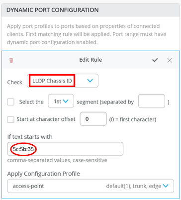
- For your dynamic port configurations to take effect, you also need to specify the ports
that you want to function as dynamic ports. You can do this by selecting the Enable
Dynamic Configuration check box on the Port Config tab in the Select
Switches section of the switch template. You can also do this at the switch level,
from the Port Configuration section on the Switch Details page.Note:
It takes a couple minutes for a port profile to be applied to a port after a client is recognized, and a couple of minutes after that for the port profile assignment status to appear on the portal.In case of switch reboots or a mass link up or down event affecting all ports on a switch, it takes approximately 20 minutes for all the ports to be assigned to the right profile (assuming that dynamic port configuration is enabled on all the ports).
- In the Select Switches Configuration section, configure the following:
- On the Info tab, create a rule to associate the shared elements with your
switch. Here's an example of how to add a rule that maps the EX4300 switch to an
"
access" role.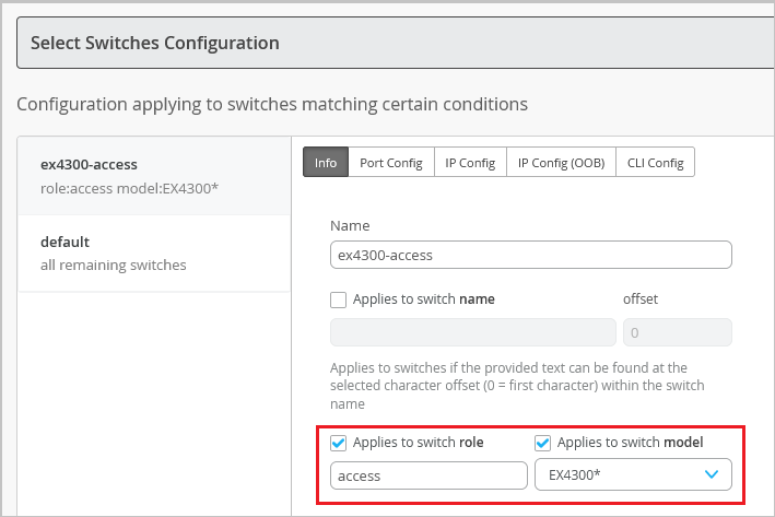
- On the Info tab, create a rule to associate the shared elements with your
switch. Here's an example of how to add a rule that maps the EX4300 switch to an
"
- On the Port Config tab, click Add Port Range to associate a port profile
with a port. Here, you also have the following key options:
- Enable Dynamic Configuration on the port. Dynamic port profiling allows you to
assign a dynamic profile to a connected device based on defined attributes. If the
device matches the attributes, Mist assigns a matching dynamic profile to the device.
But if the device doesn't match the attributes, it will be placed in a specified VLAN.
In the following example, the port is enabled with dynamic port allocation and is
assigned with a restricted VLAN. In this case, if the connected device doesn't match
the dynamic profiling attributes, it will be placed into a restricted VLAN such as a
non-routable VLAN or a guest VLAN. Interfaces enabled with Port Aggregation don't
support dynamic port configuration.
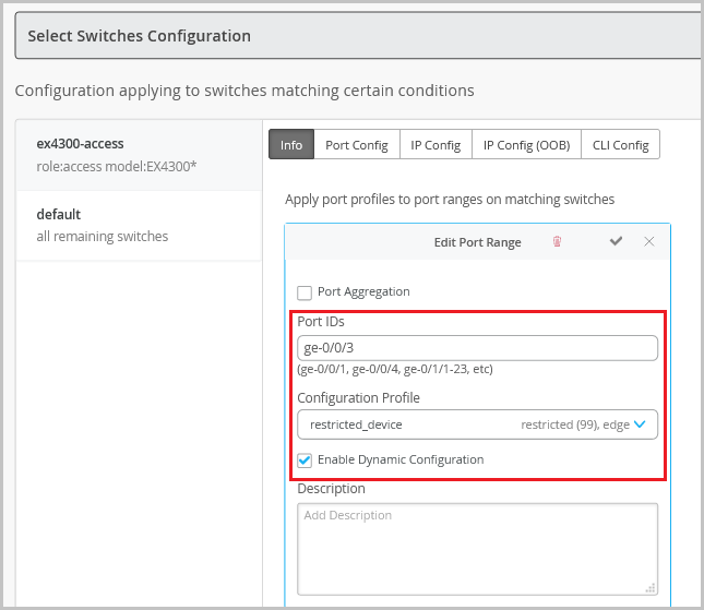
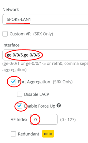
- Enable Port Aggregation. Port aggregation or link aggregation enables you to group
Ethernet interfaces to form a single link layer interface. This interface is also
known as a link aggregation group (LAG) or bundle. The number of interfaces that you
can group into a LAG and the total number of LAGs that a switch supports vary
depending on the switch model. You can use LAG with or without LACP enabled. If the
device on the other end doesn't support LACP, you can disable LACP here. You can also
configure the LACP force-up state for the switch. This configuration sets the state of
the interface as up when the peer has limited LACP capability. You can also configure
an LACP packet transmission interval. If you configure the LACP Periodic Slow option
on an AE interface, the LACP packets are transmitted every 30 seconds. By default, the
interval is set to fast in which the packets are transmitted every second. The
following example shows the use of LAG in an uplink port configuration:
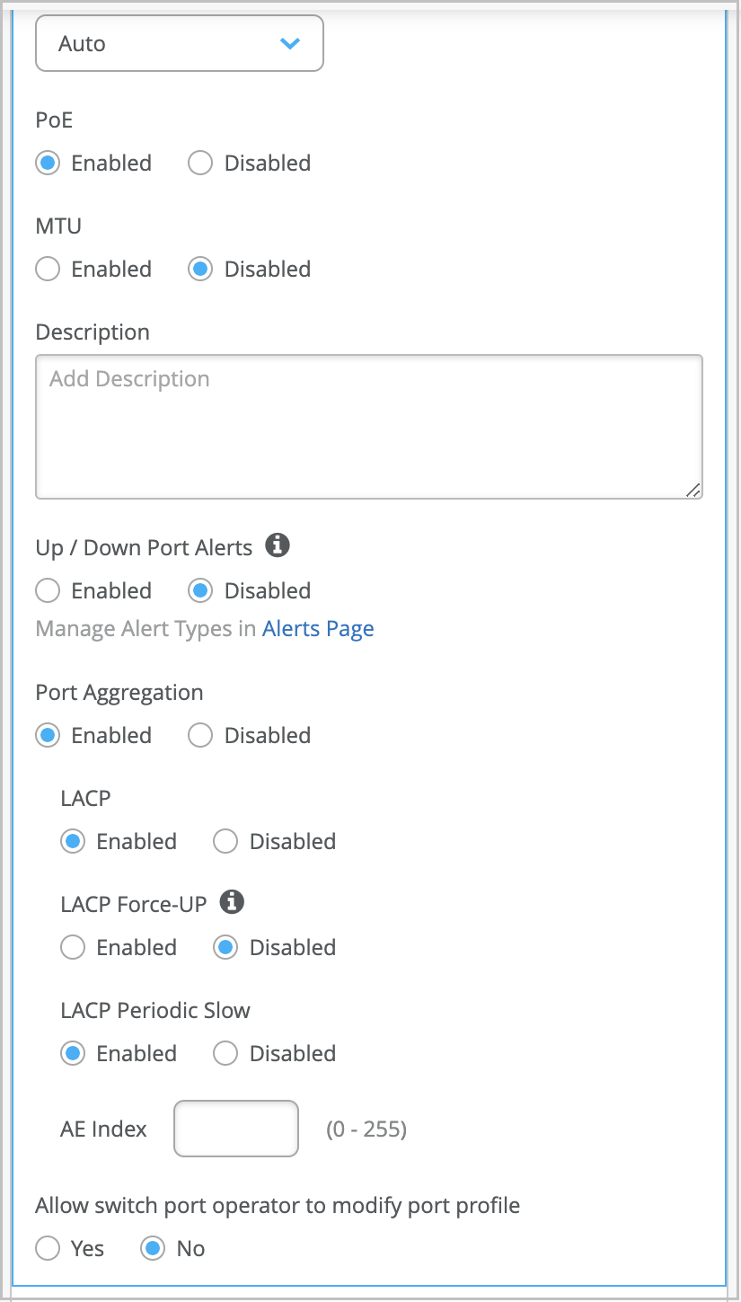
- Configure alerts and email notifications for the interface up and down events on
specified ports of a switch. To configure a switch port to support alerts, select the
Enable “Up/Down Port” Alerts check box. Also, on the Monitor > Alerts > Alerts
Configuration page, you must select from the following check boxes to enable alerts
for the ports.
- Critical WAN Edge Port Up
- Critical WAN Edge Port Down
- Critical Switch Port Up
- Critical Switch Port Down
- On the IP Config tab, you can specify a network for in-band management traffic.
- On the IP Config (OOB) tab, you can enable a dedicated management virtual routing and forwarding (VRF) instance on the switch. Enabling this feature confines the management interface (em0/me0/fxp0,vme) to a non-default VRF instance. This feature works for standalone devices and Virtual Chassis systems running Junos OS version 21.4 or later. With the dedicated management VRF instance in place, management traffic does not have to share a routing table with other control traffic or protocol traffic.
- On the CLI Config tab, include CLIs (in the set format) to configure any
additional rule-based settings for which the template doesn’t provide a GUI
option.Note:
For this JVD, the section on Group-Based Policy (GBP) configuration and Switch Policies using GBP has been removed. These features are applicable only in Campus Fabric deployments with an IP Clos architecture and are not relevant for Branch network designs.
- Enable Dynamic Configuration on the port. Dynamic port profiling allows you to
assign a dynamic profile to a connected device based on defined attributes. If the
device matches the attributes, Mist assigns a matching dynamic profile to the device.
But if the device doesn't match the attributes, it will be placed in a specified VLAN.
In the following example, the port is enabled with dynamic port allocation and is
assigned with a restricted VLAN. In this case, if the connected device doesn't match
the dynamic profiling attributes, it will be placed into a restricted VLAN such as a
non-routable VLAN or a guest VLAN. Interfaces enabled with Port Aggregation don't
support dynamic port configuration.
-
Click Save to save the switch template.
The Confirm changes window appears.
-
Click Save on the Confirm changes window.
The template is saved. To view the new template, go to Organization > Switch Templates.
Assign a Template to Sites
After creating a switch configuration template, you need to assign it to the relevant sites. This ensures that the configuration settings are applied to the devices within those sites. You have the flexibility to apply the template to a single site or multiple sites, depending on your specific requirements.
To assign a template to one or multiple sites:
- Click Organization > Switch Templates.
- The Switch Templates page appears.
- Click the template that you want to assign to sites.
- The Switch Templates: Template-Name page appears.
- Click Assign to Sites.
- The Assign Template to Sites window appears.
- Select the sites to which you want to apply the template and then click Apply.
Alternatively, you can apply a template to a site from the Site Configuration page, using the following steps:
- Click Site > Switch Configuration.
- Click a site from the list to open it.
- Select a template from the Configuration Template field, and then click Save.
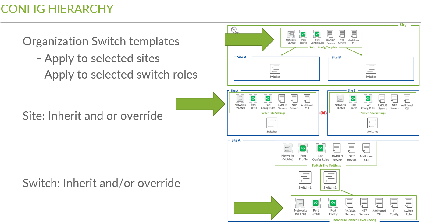
Precedence and Hierarchy of Configuration and Templates
Configuration templates have a hierarchy of assignments that you need to keep in mind when using them:
- All configs are inherited from a template to a site. All switches assigned to a site inherits the corresponding config.
- Each config element has an override option at both Site and Device levels making the configuration model extremely flexible.
- The precedence for configuration:
- The configuration highest level is applied on the Switch (Device) itself > Network (Site) > Template (Org).
Configuration Hierarchy of Templates
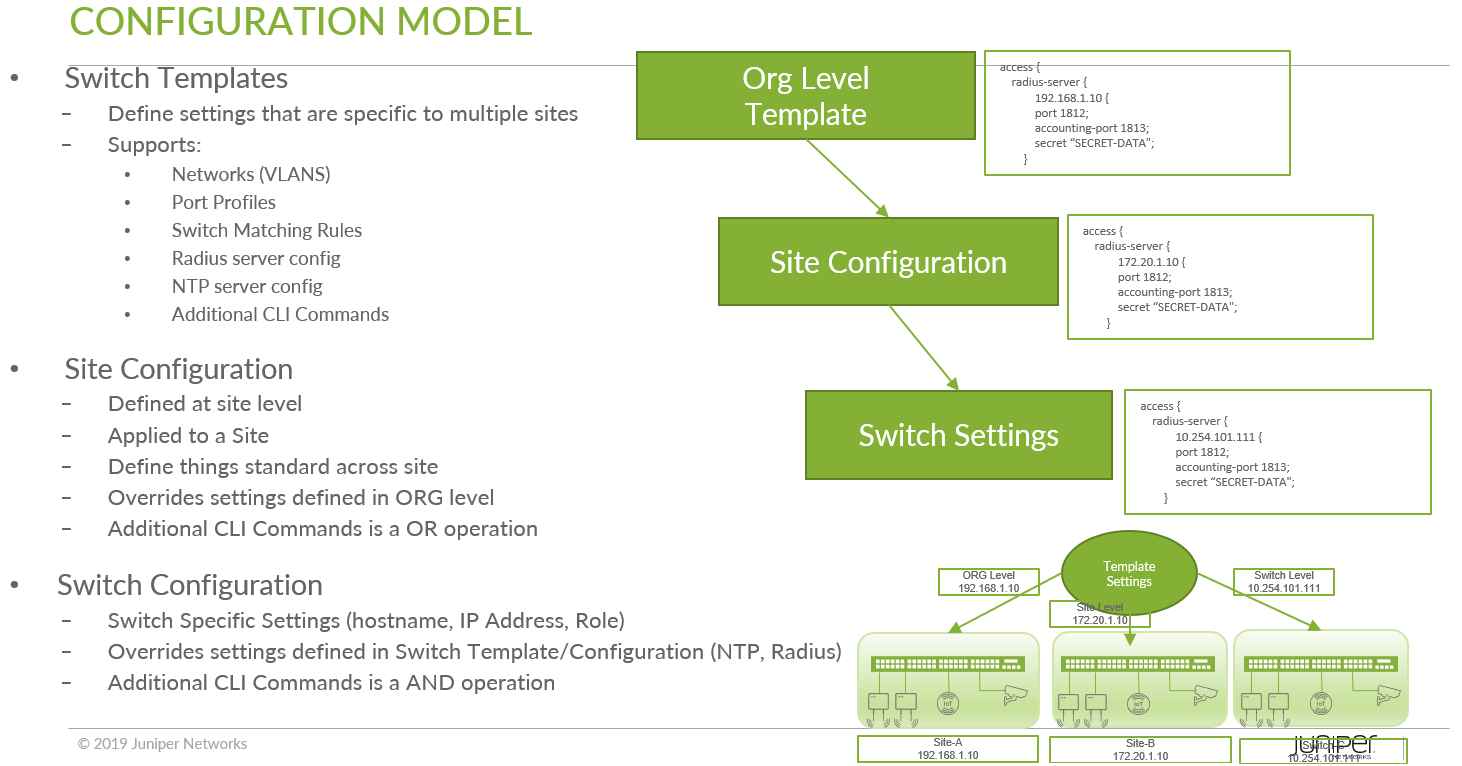
Figure 15 shows an example of the configuration hierarchy:
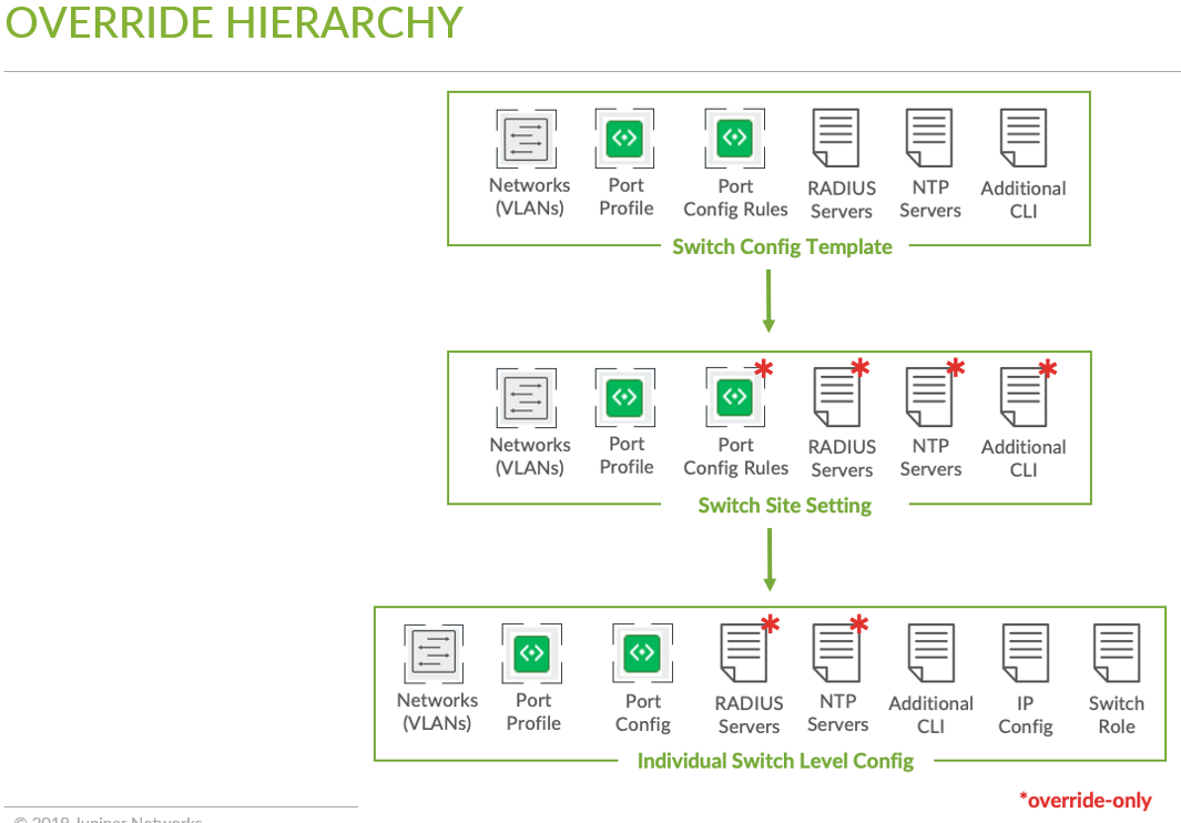
It is possible to override the configuration from upper levels in the hierarchy to create more individualized configuration in case it is needed. Figure 16 shows an example:
Unless required, it is recommended not to override at the network/site configuration. You could use site variables instead, which are explained below.
Site Variables
To minimize the number of configuration overrides at the site level, we could use the concept of site variables.
The following is an example of using site variables where we want to individually configure the DNS servers and DNS suffixes to be used:
- Go to Organization > Site Configuration and select an existing site or create a new one.
- Create a variable containing your DNS servers as a string.
- Create a variable containing your DNS suffix as a string.
-
Save the site setting.
Your two example variables should now look like the below figure:
- Go to Organization > Switch Templates and select an existing template or create a new one.
- Under DNS Settings:
- For DNS Servers=
{{dns_servers}} - For DNS Suffix=
{{dns_suffix}}.example.com
- For DNS Servers=
- Make sure the template is assigned to this site.
- Save the site setting.
Your two example configuration fields should now look like the below figure so that the right values are substituted:
More details: https://www.juniper.net/documentation/us/en/software/mist/mist-management/topics/task/site-variables.html