Appendix: Day-1 Deploy
WAN Router Installation
In this chapter, we share configuration examples for Juniper WAN routers that are also managed by the Juniper Mist cloud. Such a solution is called a “Full Stack” solution as it enables you to manage all network devices located at a branch within a single pane of glass. Those devices can be either SSR or SRX based.
Juniper SSR as WAN Router Managed by Juniper Mist Cloud
Testing with SSR WAN routers was not included in this JVD, as a separate JVD dedicated to WAN Edge for SSR had been published shortly beforehand. The integration of SSR WAN routers with branch EX Series Switches was already covered in that earlier testing process.
Refer to the JVD for WAN Edge on SSR or the SRX section in this document and take note of the following required changes:
- SSR Routers do not need the special AppID license to be installed. This is only required for SRX Series Firewalls.
- Juniper Networks® SSR Series Routers support LAG interfaces (starting with release V6.2.0) along with the suggested LACP “force-up” option starting with release V6.3.0. As it’s suggested using both when building a LAG and wanting in-band management of the switch please consider starting your deployment release V6.3.0 or higher.
- SSR Routers do not support sharing VLANs across multiple standalone interfaces or multiple LAGs. Unlike the SRX3xx Series Firewalls, this limitation must be considered during network design, or a distribution switch should be used to accommodate the required VLAN structure. It is important to review how VLANs are distributed to branch access switches, particularly when supporting wireless client roaming in scenarios where local bridging at the access point is used for breakout traffic.
- When applying the application policies, do not configure traffic steering towards the LAN as required for the SRX Series Firewalls. For SSR Routers, please implement Table 1 as shown below.
| Serial Number | Rule Name | Network | Action | Destination | Steering |
|---|---|---|---|---|---|
| 1 | Inside_Branch_hairpin | VLAN1033, VLAN1099, VLAN1088 | Pass | Branch-VLANs | N/A |
| 2 | Internet | VLAN1033, VLAN1099, VLAN1088 | Pass | any | wan |
- You must enable configuration management straight when assigning an SSR to the Site.
Juniper SRX as WAN Router Managed by Juniper Mist Cloud
Make sure the SRX Series Firewall has an AppID license or else it cannot be managed by Juniper Mist cloud. This is independent of whether you use it as a standalone firewall or as an SD-WAN router managing your VPN.
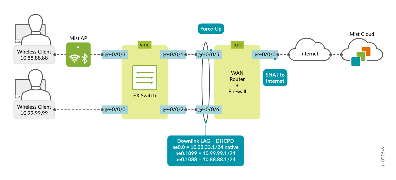
With the example below, we are sharing the minimum requirements with a standalone WAN router and a standalone EX Series Switch to establish a simple branch with in-band management of the switch over a LAG interface. You can extend this by having the EX Series Switch form a Virtual Chassis or have the WAN router form a high availability cluster pair. Unfortunately, we cannot describe all possible permutations here, so we just cover the basics.
Should your design have multiple LAGs from the WAN router towards the access switches, then you have the following options:1. When using a Juniper SRX 3xx Series Firewall, VLANs can be shared across multiple LAGs. In this setup, the Juniper Mist cloud can automatically configure IRB interfaces to support this functionality.2. When using a Juniper SRX 1500 Series Firewall or higher, you need to define a unique set of VLANs per LAG or utilize a distribution layer architecture with high availability configuration in cluster mode.
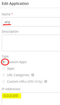
Go to Organization > Applications and check that there is an existing application with the following settings:
- Name=
any - Type=
Custom Apps - IP Addresses=
0.0.0.0/0
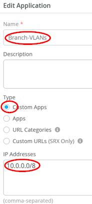
Add another application with the following settings:
- Name=
Branch-VLANs - Type=
Custom Apps - IP Addresses=
10.0.0.0/8
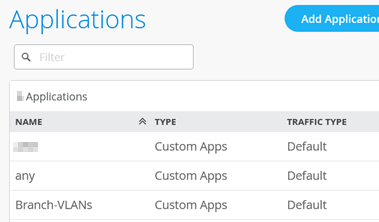
You should now see the two applications listed as shown below:
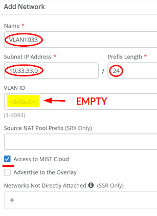
Go to Organization > Networks and add the first VLAN:
- Name=
VLAN1033 - Subnet IP Address=
10.33.33.0 - Prefix Length=
24 - VLAN ID=Leave this field empty. This is the native VLAN used for in-band management of the attached EX Series Switch as well as the AP.
- Access to Mist Cloud=
Enabled. This must be enabled for the attached switches and AP to be managed by the Juniper Mist cloud.
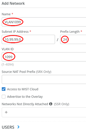
Then, add the second VLAN (in our topology we use this for wired clients):
- Name=
VLAN1099 - Subnet IP Address=
10.99.99.0 - Prefix Length=
24 - VLAN ID=
1099
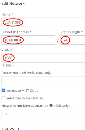
Then, add the third VLAN (in our topology, we use it for wireless clients attached through AP)
- Name=
VLAN1088 - Subnet IP Address=
10.88.88.0 - Prefix Length=
24 - VLAN ID=
1088
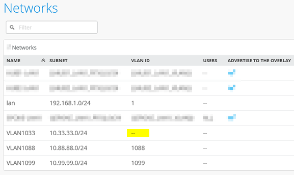
Review the three networks and verify that no VLAN ID is set for the switch and AP management network, since this is a native VLAN on the downlink trunk.
The following JSON template may be used to configure the branch WAN router. Alternatively, manual configuration steps for the branch WAN router are listed immediately after the JSON template.
{
  "type": "standalone",
  "port_config": {
    "ge-0/0/0": {
      "usage": "wan",
      "name": "wan",
      "ip_config": {
        "type": "dhcp"
      }
    },
    "ge-0/0/15": {
      "usage": "wan",
      "name": "wan2",
      "ip_config": {
        "type": "dhcp"
      }
    },
    "cl-1/0/0": {
      "usage": "wan",
      "name": "lte",
      "wan_type": "lte",
      "ip_config": {
        "type": "dhcp"
      }
    },
    "ge-0/0/5-6": {
      "usage": "lan",
      "aggregated": true,
      "ae_disable_lacp": false,
      "ae_lacp_force_up": true,
      "ae_idx": 0,
      "redundant": false,
      "critical": false,
      "disabled": false,
      "networks": [
        "VLAN1033",
        "VLAN1099",
        "VLAN1088"
      ]
    }
  },
  "ip_configs": {
    "VLAN1033": {
      "type": "static",
      "ip": "10.33.33.1",
      "netmask": "/24"
    },
    "VLAN1099": {
      "type": "static",
      "ip": "10.99.99.1",
      "netmask": "/24"
    },
    "VLAN1088": {
      "type": "static",
      "ip": "10.88.88.1",
      "netmask": "/24"
    }
  },
  "dhcpd_config": {
    "VLAN1033": {
      "type": "local",
      "ip_start": "10.33.33.10",
      "ip_end": "10.33.33.250",
      "gateway": "10.33.33.1",
      "dns_servers": [
        "8.8.8.8",
        "9.9.9.9"
      ],
      "options": {}
    },
    "VLAN1099": {
      "type": "local",
      "ip_start": "10.99.99.10",
      "ip_end": "10.99.99.250",
      "gateway": "10.99.99.1",
      "dns_servers": [
        "8.8.8.8",
        "9.9.9.9"
      ],
      "options": {}
    },
    "VLAN1088": {
      "type": "local",
      "ip_start": "10.88.88.10",
      "ip_end": "10.88.88.250",
      "gateway": "10.88.88.1",
      "dns_servers": [
        "8.8.8.8",
        "9.9.9.9"
      ],
      "options": {}
    }
  },
  "path_preferences": {
    "wan": {
      "paths": [
        {
          "type": "wan",
          "name": "wan"
        }
      ]
    },
    "LAN": {
      "strategy": "ordered",
      "paths": [
        {
          "type": "local",
          "networks": [
            "VLAN1033"
          ]
        },
        {
          "type": "local",
          "networks": [
            "VLAN1099"
          ]
        },
        {
          "type": "local",
          "networks": [
            "VLAN1088"
          ]
        }
      ]
    }
  },
  "service_policies": [
    {
      "name": "inside_Branch_hairpin",
      "tenants": [
        "VLAN1033",
        "VLAN1088",
        "VLAN1099"
      ],
      "services": [
        "Branch-VLANs"
      ],
      "action": "allow",
      "path_preference": "LAN",
      "idp": {
        "enabled": false
      }
    },
    {
      "name": "Internet",
      "tenants": [
        "VLAN1033",
        "VLAN1099",
        "VLAN1088"
      ],
      "services": [
        "any"
      ],
      "action": "allow",
      "path_preference": "wan",
      "idp": {
        "enabled": false
      }
    }
  ],
  "bgp_config": {},
  "routing_policies": {},
  "extra_routes": {},
  "vrf_instances": {},
  "tunnel_configs": {},
  "oob_ip_config": {
    "type": "dhcp",
    "node1": {
      "type": "dhcp"
    }
  },
  "ntp_servers": [
    "time.google.com"
  ],
  "dns_servers": [
    "8.8.8.8",
    "9.9.9.9"
  ],
  "tunnel_provider_options": {
    "jse": {},
    "zscaler": {}
  },
  "additional_config_cmds": [
    "set security zones security-zone VLAN1033 host-inbound-traffic system-services ping",
    "set security zones security-zone VLAN1099 host-inbound-traffic system-services ping",
    "set security zones security-zone VLAN1088 host-inbound-traffic system-services ping"
  ],
  "name": "Branch-WAN-Router"
}
When not using the JSON template, execute the following steps instead to configure the branch WAN router:
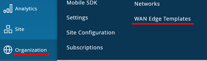
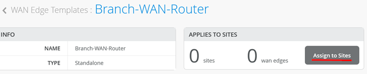
Go to Organization > WAN Edge Templates
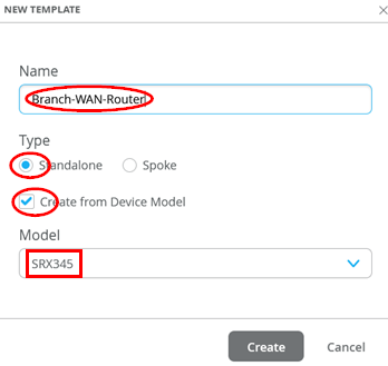
Create a new template with the following parameters:
- Name=
Branch-WAN-Router - Type=
Standalone - Create from Device Model=
Checked - Model=
<Select your Model>
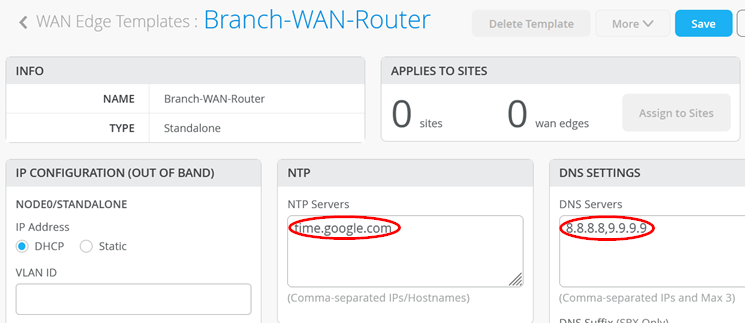
After the template has been created, start with basic configuration settings based on your environment such as the following:
- NTP=
time.google.com - DNS Servers=
8.8.8.8, 9.9.9.9
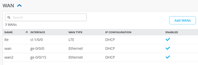
When you check the template, you should see the following
preconfigured WAN interfaces. We are going to use the
“wan” ge-0/0/0 interface to obtain a DHCP
lease from the broadband router.
We are going to modify the LAN interfaces of this template. Delete the preconfigured “lan” interface (not shown here).
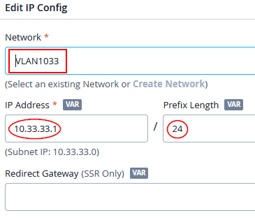
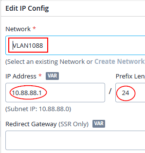
Then, create a first LAN network (native for our device management) with the following IP config:
- Network=
VLAN1033 - IP Address=
10.33.33.1 - IP-Prefix Length=
24
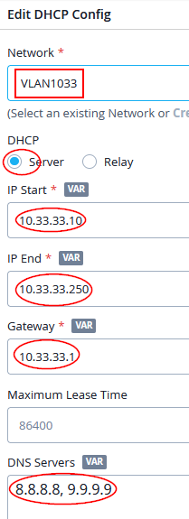
Configure with the following DHCP config:
- Network=
VLAN1033 - DHCP=
Server - IP Start=
10.33.33.10 - IP End=
10.33.33.250 - Gateway=
10.33.33.1 - DNS Servers=
8.8.8.8, 9.9.9.9
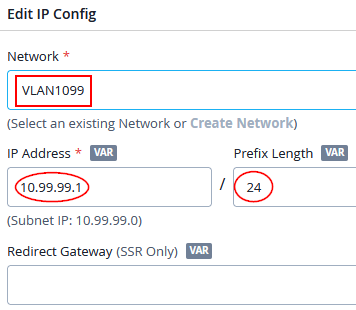
Then, create a second LAN network (trunked for our wired clients) with the following IP config:
- Network=
VLAN1099 - IP Address=
10.99.99.1 - IP-Prefix Length=
24
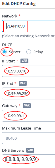
Configure with the following DHCP config:
- Network=
VLAN1099 - DHCP=
Server - IP Start=
10.99.99.10 - IP End=
10.99.99.250 - Gateway=
10.99.99.1 - DNS Servers=
8.8.8.8, 9.9.9.9
Then, create a third LAN network (trunked for our wireless clients) with the following IP config:
- Network=
VLAN1088 - IP Address=
10.88.88.1 - IP-Prefix Length=
24
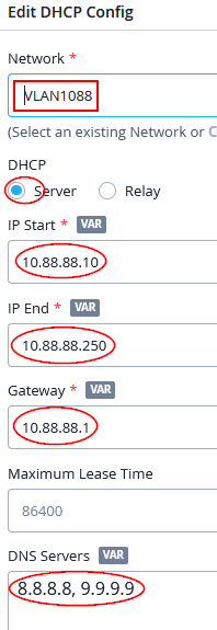
Configure with the following DHCP config:
- Network=
VLAN1088 - DHCP=
Server - IP Start=
10.88.88.10 - IP End=
10.88.88.250 - Gateway=
10.88.88.1 - DNS Servers=
8.8.8.8, 9.9.9.9
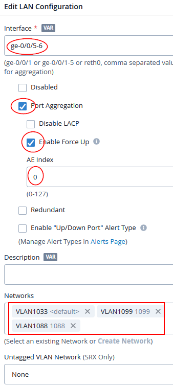
Finally, configure the LAN interfaces with LAG and the Force-Up option binding the three networks together:
- Interface=
ge-0/0/5-6 - Port aggregation=
Enabled - Disable LACP=
Unchecked(default) - Enable Force Up=
Enabled - AE Index=
0 - Network=
VLAN1033andVLAN1099andVLAN1088
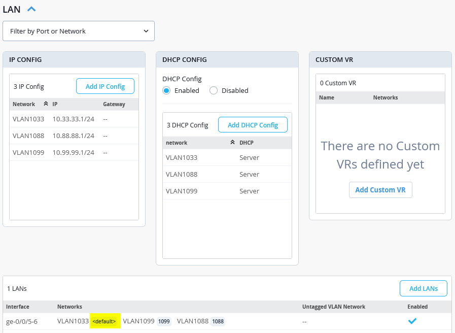
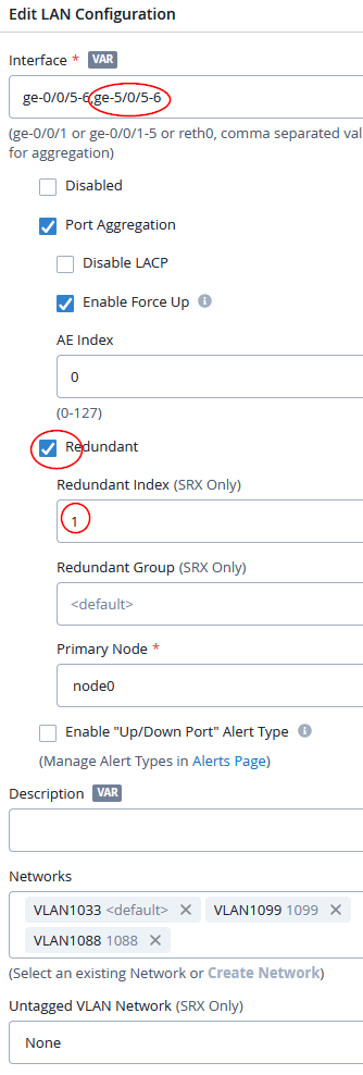
The final LAN interface table should look like the figure below:
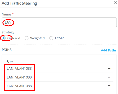
Next step is adding a new destination to the traffic steering policy. This is required to enable communication between the local VLANs which we want to happen in our example. Add a new traffic steering policy using the following settings:
- Name=
LAN - Strategy=
Ordered - Paths:
- Type=
LAN: VLAN1033 - Type=
LAN: VLAN1099 - Type=
LAN: VLAN1088
- Type=
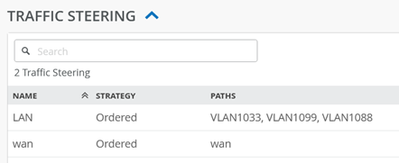
You should see the following for traffic steering destinations now:
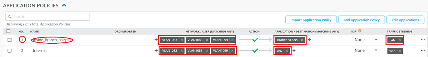
Implement Table 2 for application policies when your device is an SRX Series Firewall. Parts should already exist that you only need to modify.
| Serial Number | Rule Name | Network | Action | Destination | Steering |
|---|---|---|---|---|---|
| 1 | Inside_Branch_hairpin | VLAN1033, VLAN1099, VLAN1088 | Pass | Branch-VLANs | LAN |
| 2 | Internet | VLAN1033, VLAN1099, VLAN1088 | Pass | any | wan |
You should see the following configuration for application policies now after the implementation of the above table:
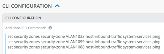
In the current version, clients on the LAN side cannot get an answer when sending ICMP pings to the WAN router as their local gateway. However, receiving pings is crucial for any local debugging. Hence, it is highly recommended that you add some additional Junos OS CLI commands to enable ping for any wired or wireless clients towards the WAN router as the local gateway of the VLAN they are attached to. See the example below:
set security zones security-zone VLAN1033 host-inbound-traffic system-services ping
set security zones security-zone VLAN1099 host-inbound-traffic system-services ping
set security zones security-zone VLAN1088 host-inbound-traffic system-services ping
In the portal, it should look like the figure below:
Click Save to save the template now.
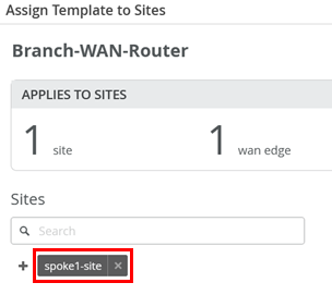
You must assign a site for this template or else it won’t be used on any device.
Here, we add the Spoke1 site to the template, which is where our switches are located.
To assign your SRX Series Firewall devices to sites, the devices must be present in the Juniper Mist inventory. You can claim or adopt your SRX Series Firewall to onboard it in the Juniper Mist cloud. After the device is onboarded, the organization inventory shows the device.
To assign an SRX Series Firewall to a site:
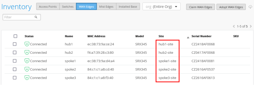
- In the portal, click Organization > Admin > Inventory.
- Refresh your browser and check under WAN Edges to find out if your SRX Series Firewall is part of the inventory.
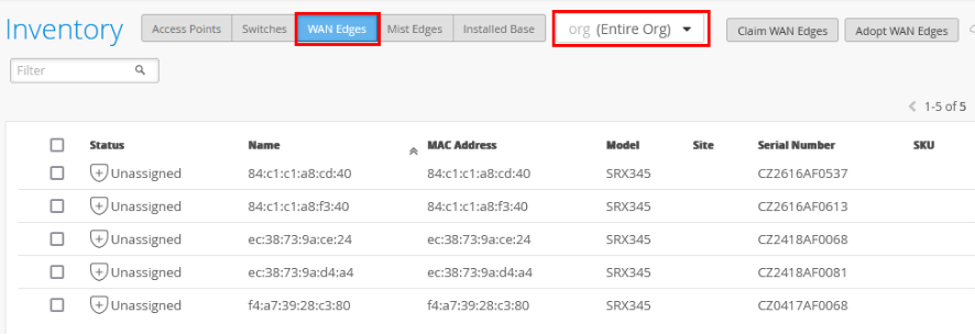
- Assign each SRX Series Firewall to an individual site using the Assign to Site option.
- On the Assign WAN Edges page, select the site you want to assign from the list of available sites.
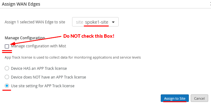
- Do not select the Manage configuration with Mist option. If you do, you may see unwanted changes to the configuration on your SRX Series Firewall. You can enable the option later if required, after you've assigned the device to the site.
- Check the Use site setting for APP Track license option if you have a valid Application Security license, and then click Assign to Site.
The figure below shows changes in the inventory once you assign the device to the site:
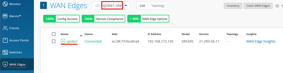
- After the device is onboarded, on the WAN Edges tab, select <your site> and then click on the device.
- Check the device and AppSecure status:
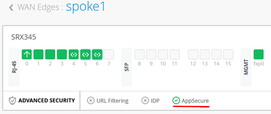
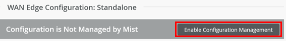
- Now click Enable Configuration Management to activate it as the last step so that Mist can configure the device:
- OPTIONAL: Use a remote console to verify the device
configuration and status after Juniper Mist cloud takes over
management of the device. In our example, you see the below output:
root@spoke1> show interfaces terse
Interface               Admin Link Proto    Local                 Remote
ge-0/0/0                up    up
ge-0/0/0.0              up    up   inet     192.168.173.145/24
.
ge-0/0/5                up    up
ge-0/0/5.0              up    up   aenet    --> ae0.0
ge-0/0/5.1088           up    up   aenet    --> ae0.1088
ge-0/0/5.1099           up    up   aenet    --> ae0.1099
ge-0/0/5.32767          up    up   aenet    --> ae0.32767
ge-0/0/6                up    up
ge-0/0/6.0              up    up   aenet    --> ae0.0
ge-0/0/6.1088           up    up   aenet    --> ae0.1088
ge-0/0/6.1099           up    up   aenet    --> ae0.1099
ge-0/0/6.32767          up    up   aenet    --> ae0.32767
.
ae0                     up    up
ae0.0                   up    up   inet     10.33.33.1/24
ae0.1088                up    up   inet     10.88.88.1/24
ae0.1099                up    up   inet     10.99.99.1/24
ae0.32767               up    up
.
root@spoke1> show lacp interfaces
Aggregated interface: ae0
    LACP state:       Role   Exp   Def  Dist  Col  Syn  Aggr  Timeout  Activity
      ge-0/0/5 FUP    Actor   No    No   Yes  Yes  Yes   Yes     Fast    Active
      ge-0/0/5 FUP  Partner   No   Yes    No   No  Yes   Yes     Fast   Passive
      ge-0/0/6       Actor    No   Yes    No   No   No   Yes     Fast    Active
      ge-0/0/6     Partner    No   Yes    No   No   No   Yes     Fast   Passive
    LACP protocol:        Receive State  Transmit State          Mux State
      ge-0/0/5 FUP              Current   Fast periodic Collecting distributing
      ge-0/0/6                Defaulted   Fast periodic           Detached
The moment you attach the EX Series Switch and power it up, it should obtain a DHCP lease from the WAN router which you can verify as shown below. From time to time, you should also see the Phone Home Client on the switch trying to contact the redirect server as in our example:
root@spoke1> show dhcp server binding detail
Client IP Address:  10.33.33.11
     Hardware Address:             04:5c:6c:6b:13:42
     State:                        BOUND(LOCAL_SERVER_STATE_BOUND)
     Protocol-Used:                DHCP
     Lease Expires:                2024-03-07 17:02:09 UTC
     Lease Expires in:             85474 seconds
     Lease Start:                  2024-03-06 17:02:09 UTC
     Last Packet Received:         2024-03-06 17:02:09 UTC
     Incoming Client Interface:    ae0.0
     Client Interface Vlan Id:     1
     Server Identifier:            10.33.33.1
     Session Id:                   2
     Client Pool Name:             VLAN1033
root@spoke1> show security flow session source-prefix 10.0.0.0/8
Session ID: 249108247036, Policy name: 01_Internet/20, State: Stand-alone, Timeout: 854, Valid
  In: 10.33.33.11/59874 --> 44.231.144.179/443;tcp, Conn Tag: 0x0, If: ae0.0, Pkts: 8, Bytes: 1278,
  Out: 44.231.144.179/443 --> 192.168.173.145/8983;tcp, Conn Tag: 0x0, If: ge-0/0/0.0, Pkts: 18, Bytes: 13734,
Total sessions: 1
The example below illustrates the use of SRX Series Firewalls in a redundant cluster configuration. At the time this JVD was created, the required configuration could not be fully completed through the GUI. Therefore, a hybrid approach was used: redundant Ethernet interfaces were configured through the GUI, while the LAG interfaces—with the “force-up” option—were manually added via the CLI within the same template.
SRX Chassis Cluster
When using SRX Series Firewalls in chassis cluster mode, you need to configure a minimum of 4 links when using LAGs as it is not possible to span a single aggregate Ethernet bundle across the two redundant cluster nodes. Instead, you form individual aggregate Ethernet bundles on each local cluster node and bind those together through a redundant Ethernet interface called a “reth” interface. You can find an example topology in Figure 2:
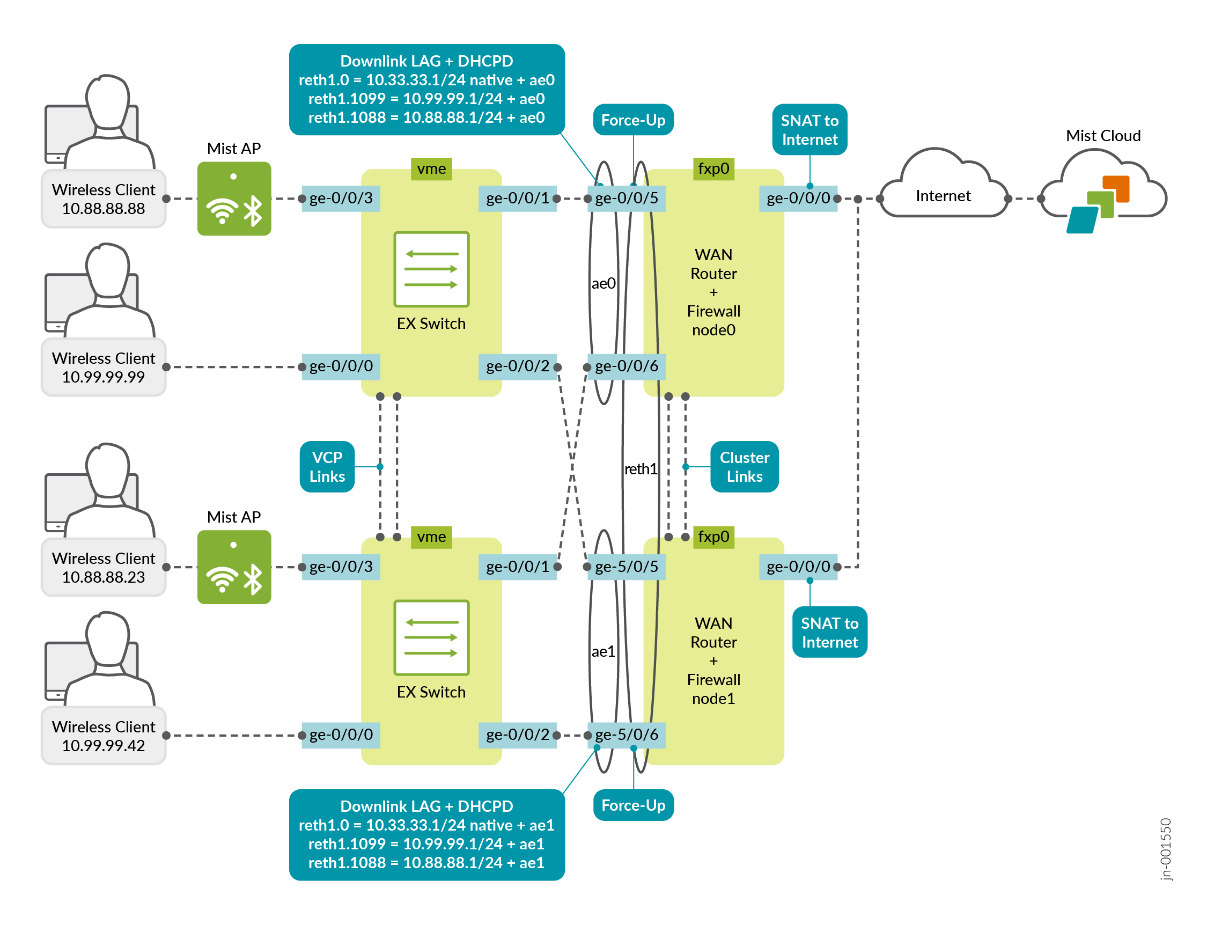
When changing the configuration :
- The Interface field must have all four interface names that are distributed across all cluster nodes. On node1, the interface name is always renamed when the cluster is built. What the exact new interface name will be is device specific and you can review more information here.
- You need to add the redundant interface option to your existing LAG configuration.
In the example below, we added the following configuration:
- Interface=
ge-0/0/5-6, ge-5/0/5-6 - Redundant=
Enabled- Redundant Index=
1 - Redundant Group=
empty(default) - Primary Node=
Node0
- Redundant Index=
Activating a Greenfield Switch via Claim and ZTP-Based Installation
A switch-specific QR code is set up at the time of purchase. The switch will arrive in a box with the cloud-ready logo, and a sticker with a QR code will be on the back of the switch near the fan exhaust and interfaces.
Using the MistAI App to add a cloud-ready switch to the Juniper Mist cloud
Step-by-Step Procedure:
- Download and install the MistAI app to your phone.
- Unbox your switch, connect the management port to the Internet, and power it on. As part of the ZTP process, the switch will automatically access the PHC server (or the DHCP server if you have set this up instead) and then connect to the Juniper Mist cloud for configuration updates.
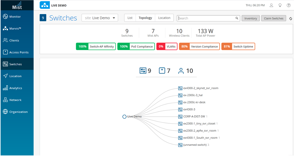
- Using a web browser, log in to your Juniper Mist account. The
Monitor screen appears, showing an overview of the
Juniper Mist cloud and any APs and clients that are already
connected. In the menu on the left, click Switches
to open that screen. Once the ZTP process resolves, the switch will
automatically appear here (if the switch doesn’t appear after
a few minutes, despite refreshing the web page, log out and then
log back in, or go to the troubleshooting section below to find out
how to confirm whether the device is connecting to the cloud.
- While the switch is being resolved in the Juniper Mist cloud, find the QR code on the front of the switch.
- On your phone, open the MistAI app and log into your Juniper
Mist cloud account. Tap the Claim AP to Org button
that appears.
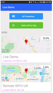
- Point the QR code viewer at the QR code on your switch. Once the QR code comes into focus (that is, your camera is held at the right distance), the app automatically claims the device and adds it to your organization’s inventory in the portal.
Manually Adding a Cloud-Ready Switch to the Juniper Mist Cloud
Step-by-Step Procedure:
To adopt a cloud-ready switch manually, you need an activation code for the switch (these are sent via email to the address on record at the time of purchase, or they can be obtained by contacting the Juniper Mist Customer Engagement team). Using the activation code will adopt the switch and any Juniper APs that are part of the purchase order, as well as claiming any subscriptions that are included in your purchase.
- Start by unboxing your switch, connecting the management port to the Internet, and powering it on. As part of the ZTP process, the switch will automatically access the PHC server (or the DHCP server if you have set this up instead) and then connect to the Juniper Mist cloud for configuration updates.
- Using a web browser, log in to your Juniper Mist account. The
Monitor screen appears, showing an overview of the
Juniper Mist cloud and any Juniper APs and clients that are already
connected. In the menu on the left, click Organization >
Inventory to open that screen.
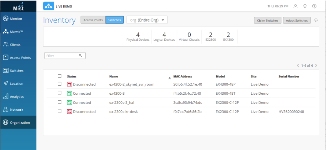
- Choose the Switches tab at the top of the Inventory screen, and
then click the Claim Switches button and enter the
claim code or activation code for the switch.
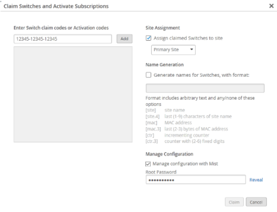
- Fill out the other fields on the screen as you like. Note that if you deselect Assign claimed switches to site, the switch will not be listed in the Switches page. To see your switch on the Switches page, you must first assign the switch to the site from the Inventory page. Check Manage configuration with Juniper Mist and then enter a root password for the switch. Note that this choice puts the switch under the management of Mist, and as such, Juniper recommends that local configuration using the CLI be restricted to prevent conflicts (for example, you may want to create a system login message on the switch to warn against making configuration changes locally, from the CLI).
- Once the ZTP process resolves, the switch will automatically appear on the Inventory screen. If the switch doesn’t appear after a few minutes despite refreshing the web page, log out and then log back in, or go to the troubleshooting section below to find out how to confirm whether the device is connecting to the cloud.
Activating a Brownfield Switch via Adoption Code-Based Installation
It is important to backup your existing Junos OS configuration on the switch before activating a
brownfield switch, because when the switch is adopted for management from the Juniper Mist
cloud, as described below, the old configuration will be replaced. Do this by running the
request system software configuration-backup <path> command,
which saves the currently active configuration and any installation-specific
parameters.
To prevent users from using the Junos OS CLI to configure the switch after it has been adopted into the Juniper Mist cloud, you may want to create a system login message on the switch to warn against making configuration changes, or to restrict their management access altogether by changing the password or placing restrictions on the Junos OS CLI user accounts.
Switch adoption will always use outbound SSH initially. Even if one has a CloudX ready switch with JMA installed the system is unable to know that upfront. The least common determinator is outbound-ssh for all switches that should be managed by Mist cloud. Once the Switch is fully managed by Mist Cloud, and JMA installed, the outbound-ssh capability may be deactivated and CloudX via HTTPS used from then on.
This procedure describes how to set up a secure connection between a supported EX Series Switch running a supported version of Junos OS. In it, you will make a few configuration changes on the portal as well as some on the switch using the Junos OS CLI. Be sure you can log on to both systems.
- Log in to your organization on the Juniper Mist cloud and then click Organization > Inventory in the menu.
- Choose Switches at the top of the screen that
appears, and then click the Adopt Switch button in
the upper right corner to generate the Junos OS CLI commands needed
for the interoperability. The commands create a Juniper Mist user
account, and a SSH connection to the Juniper Mist cloud over TCP
port 2200 (the switch connection is from a management interface and
is used for configuration settings and sending telemetry data).
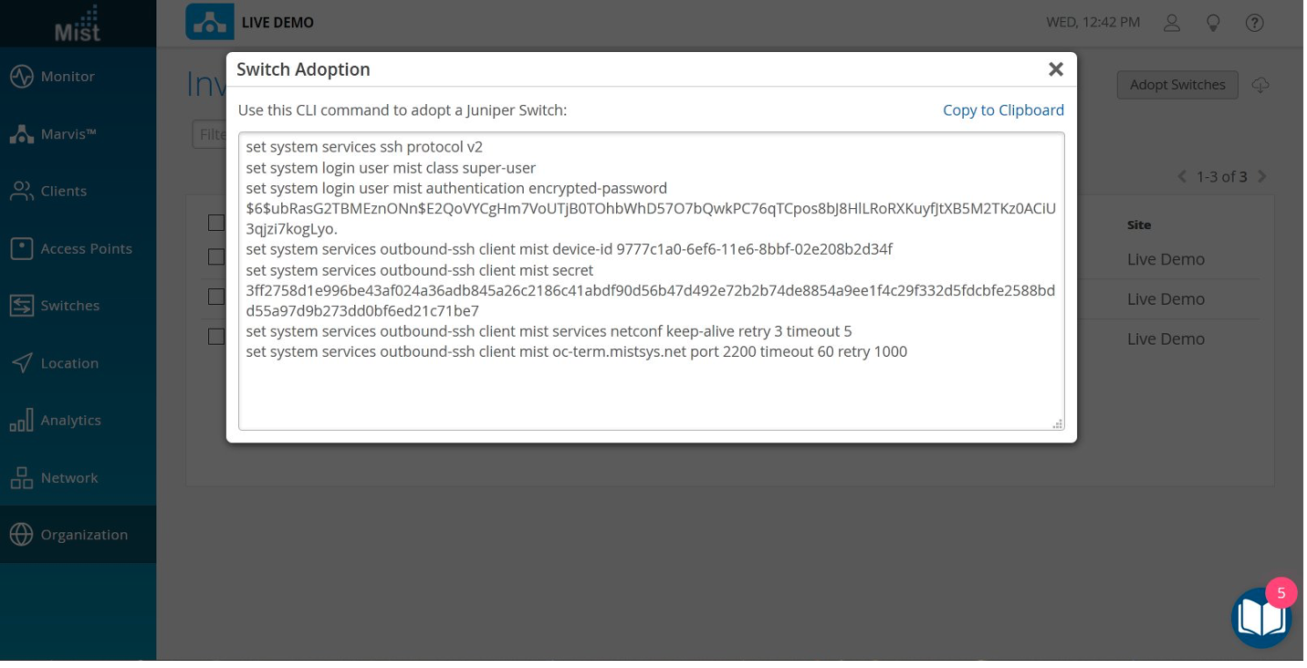
- In the window that appears, click Copy to Clipboard to get the commands from the Juniper Mist cloud.
- At the Junos OS CLI, type “edit” to start configuration mode, and then paste the commands you just copied (type “top” if you are not already at the base level of the hierarchy).
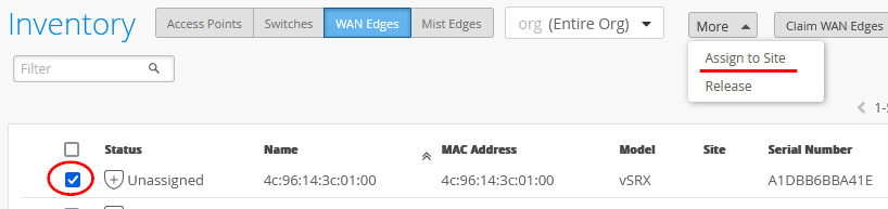
- Back in the portal, click Organization > Inventory > Switches and select the switch you just added.
- Click the More drop-down at the top of the screen, and then the Assign to Site button to continue making your selections as prompted.
- Confirm your updates on the switch by running show commands at
the system services level of the hierarchy, and again at the system
login user juniper-mist level of the hierarchy.
cli
show configuration system services
ssh {
    protocol-version v2;
}
netconf {
    ssh;
}
outbound-ssh {
    client mist {
        device-id 3634a49d-3e20-46d6-b0c9-0b0d6a314690;
        secret "trimmed"; ## SECRET-DATA
        keep-alive {
            retry 12;
            timeout 5;
        }
        services netconf;
        oc-term.mistsys.net {
            port 2200;
            retry 1000;
            timeout 60;
        }
    }
}
show configuration system login user mist
full-name mist;
uid 63157;
class super-user;
authentication {
    encrypted-password "trimmed"; ## SECRET-DATA
    ssh-rsa "trimmed"; ## SECRET-DATA
}
The Junos OS CLI for adoption is unique to the Mist organization itself. Once retrieved, you can use it on other EX Series Switches that belong to the same organization. After first contacting the Juniper Mist cloud, the default passwords are going to be changed to unique passwords per device.
Add the Switch to the Juniper Mist Portal and View Details
Now that the switch is able to register with the portal, the next steps are to add the switch to the appropriate site and to assign APs. You do this from the portal.
Step-by-Step Procedure:
- To add the switch to a site, click Organization > Inventory in the Juniper Mist menu and then the Switches tab at the top of the screen that appears. Select the switch you just added, and then click the More button, Assign to Site, and then choose a site from the drop-down list that appears in the Assign Switches window. Click the Assign to Site button to complete the action.
- Click Access Points to see a list of unassigned APs.
- Click Switches to see the list of switches.
You can choose a switch from the list to confirm that it and the
portal are correctly provisioned. Note that the PoE compliance you
set up earlier on the switch interfaces is shown with the switch,
as are the VLANs and other details.
- From the Switches page, click a switch name to drill down into
a detailed view of that switch, including connected APs and
clients. For each switch on the list, you can view various
properties, including the version, model number, CPU and memory
utilization, bytes transferred, power drawn by the PoE devices, and
port errors.
- Finally, as the stepping off point of this JVD, open a Junos OS shell from the portal by selecting the switch you just added and then clicking Open Shell in the upper right corner of the Switches screen. From here, you have full read and write access to the switch for any further configuration changes you wish to make.
EX Series Switch Behind a WAN Router
Now it is time to onboard your switch and add it to your infrastructure. We assume in this example that we form a LAG with the WAN router and that we use the force-up method described in the previous chapter Best practices when using Link Aggregation on the uplink Interfaces.
To assign a switch to a site:
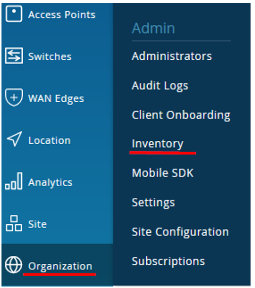
- In the
portal, click Organization > Admin >
Inventory.
Figure 3: Navigating to Inventory
- In the Inventory page, ensure the inventory view is set to org
(Entire Org) and refresh your browser until you see all of your
devices.
Figure 4: EX Series Switch in Inventory
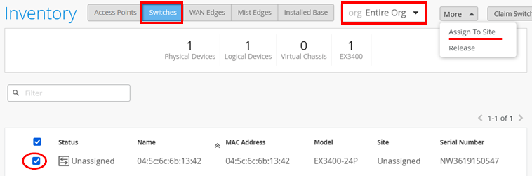
- Select your new switch and click Assign to Site.
- On the Assign Switches page:
- Select
spoke1-site. -
Disable Manage configuration with Mist option.
You can enable this option at a later stage, if required.
Figure 5: Selecting Site for Assigning Switch
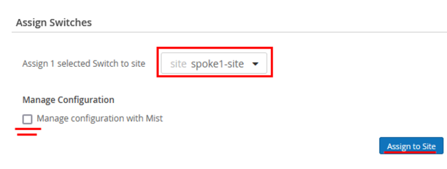
- Select
- Click Assign to Site.
- Confirm the changes in the inventory once you assign the device to the site.
- You can see
spoke1-siteunder New Site.Figure 6: Assigned Switch to Site Details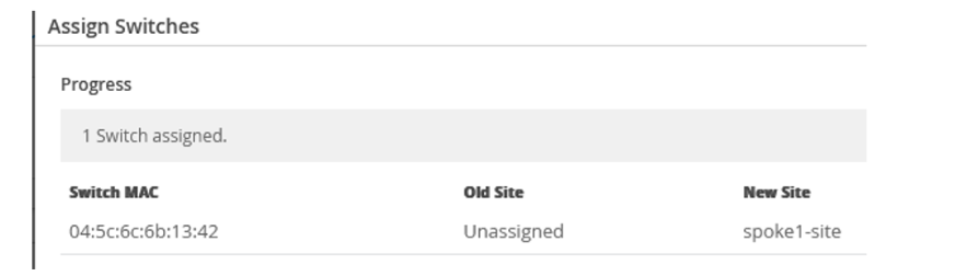
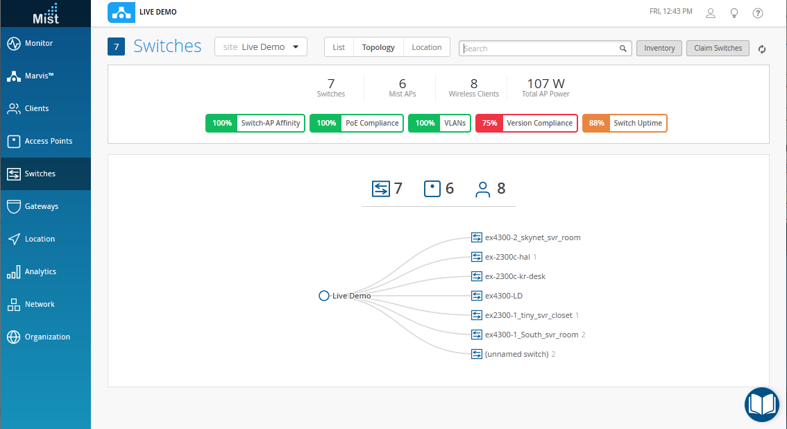
- In the portal, go to Switches and select spoke1-site.
Figure 7: Selecting Assigned Switch for Modification
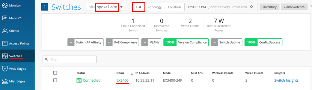
The page displays the list of switches assigned to the site.
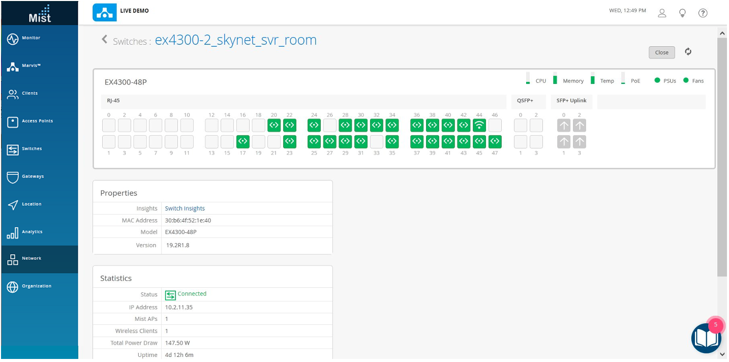
- Click the required switch to open the switch configuration page.
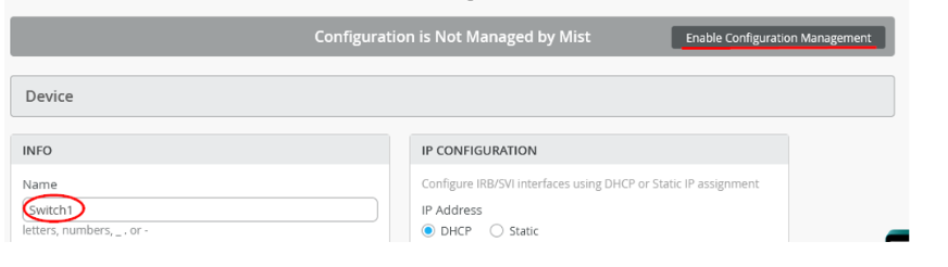
- Verify the device name, then scroll down to the Switch
Configuration section and check Enable
Configuration Management.
Figure 8: Configuration of Assigned Switch
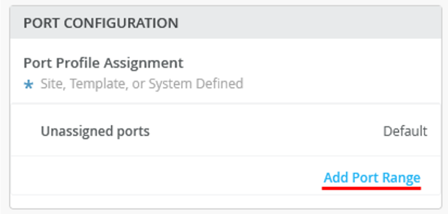
- Under Port Configuration, click Add Port
Range.
Figure 9: Port Configuration of Assigned Switch
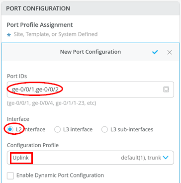
- On the New Port Range page, configure the
following options:
- Set the
Port IDs as
ge-0/0/1andge-0/0/2(two ports for the LAG). - For the interface, select the default “
L2 Interface”. - Select the existing Configuration Profile as
“
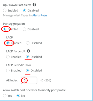
Uplink”. - Enable Port Aggregation.
- Enable LACP to detect a failed or broken link.
- Disable force-up. You need to enable this option only on the WAN router or if this is a distribution switch where you configure a downlink towards an access switch.
- Leave LACP periodic slow disabled.
- Set the AE Index to 0 to ensure that the AE index is the same
on both sides.
Figure 10: Port Configuration of Assigned Switch
- Set the
Port IDs as
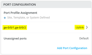
- The figure below shows the summary of the port configuration.
Figure 11: Port Configuration of Assigned Switch
- Save your changes.

You’ve now added a new EX Series Switch to your Juniper Mist Wired Assurance deployment.
Optionally, you can confirm that your switch has the two links up by using remote shell as shown in the following sample output:
              show lacp interfaces
Aggregated interface: ae0
    LACP state:       Role   Exp   Def  Dist  Col  Syn  Aggr  Timeout  Activity
      ge-0/0/1       Actor    No    No   Yes  Yes  Yes   Yes     Fast    Active
      ge-0/0/1     Partner    No    No   Yes  Yes  Yes   Yes     Fast    Active
      ge-0/0/2       Actor    No    No   Yes  Yes  Yes   Yes     Fast    Active
      ge-0/0/2     Partner    No    No   Yes  Yes  Yes   Yes     Fast    Active
    LACP protocol:        Receive State  Transmit State          Mux State
      ge-0/0/1                  Current   Fast periodic Collecting distributing
      ge-0/0/2                  Current   Fast periodic Collecting distributing
Troubleshooting Tips
In this chapter, we share more information about the connection between the switch and Juniper Mist cloud. Please also review the article How does an EX Series Switch connect to the Juniper Mist Cloud to get managed? where we introduced these methods in case you skipped it.
In case you encounter any issue with the onboarding process with the Juniper Mist cloud, taking the steps below may help with resetting a device and ensure further communication to the Juniper Mist cloud. An external reference is available through the following link: https://www.mist.com/documentation/troubleshooting-switches/
Check Any Firewall Between EX Series Switch and Mist Cloud Communication
We assume that you have implemented the protocols and port openings on your firewall as described here. For EX Series Switch management, the three most important protocols and port openings are:
-
For Outbound SSH connections towards Juniper Mist
cloud: TCP to destination port 2200. The EX Series Switch
establishes an outbound SSH session to pass a source NAT towards
the Internet which works in the following way:
- The device uses a raw socket for a TCP connection to the Juniper Mist cloud.
- Once the TCP connection is established, the device sends a special DMI message so that the Juniper Mist cloud gathers information such as the device serial number to determine which devices need to be managed.
- If the Juniper Mist cloud has identified the device based on the DMI, it uses the existing TCP connection to establish a reverse SSH session back to the device with the credentials known for SSH login.
- It is critical that the firewall vendor does not attempt to apply any kind of further application-level management looking deeper into the session. It can be assumed that the special DMI message and reverse SSH login are unknown applications. This TCP 2200 port session must not be inspected deeper and must be treated as raw all the time.
-
For Claim and ZTP of the Switch: An HTTPS
TLS-encrypted session towards destination port 443 towards FQDN
redirect.juniper.net. This is required for the ZTP process to work and for the device to retrieve the initial config to attach to the correct Juniper Mist cloud. If for some reason this is not possible, consider the brownfield adoption method instead. -
For CloudX connections towards Juniper Mist
cloud: You need to open an HTTPS TLS-encrypted session
towards destination port 443 towards the Juniper Mist cloud. Here,
the firewall vendor can apply application-level management for the
TLS session. The destination FQDN is usually
jma-terminator.<cloud>.mist.com
The recommendation is that you open both ports required for outbound SSH and CloudX operation. When unboxing a new switch, you may not have the JMA client installed as part of the factory-installed Junos OS version. Also, the adoption method uses outbound SSH initially to manage the device.
If you have console access to the device you can try the following check:
# test you can ping a site in the internet
root> ping 8.8.8.8
PING 8.8.8.8 (8.8.8.8): 56 data bytes
64 bytes from 8.8.8.8: icmp_seq=0 ttl=53 time=5.371 ms
64 bytes from 8.8.8.8: icmp_seq=1 ttl=53 time=5.175 ms
# test DNS working as well
root> ping www.google.com inet
PING www.google.com (142.251.32.36): 56 data bytes
64 bytes from 142.251.32.36: icmp_seq=0 ttl=112 time=24.966 ms
64 bytes from 142.251.32.36: icmp_seq=1 ttl=112 time=18.031 ms
64 bytes from 142.251.32.36: icmp_seq=2 ttl=112 time=9.661 ms
64 bytes from 142.251.32.36: icmp_seq=3 ttl=112 time=8.440 ms
Switches Using Outbound SSH as the Connection Towards Juniper Mist Cloud
For the next step, you need to know the FQDN of the management instance of the Juniper Mist cloud. You get this information by going to Organization > Inventory and then selecting Switches and then clicking Adopt Switches.
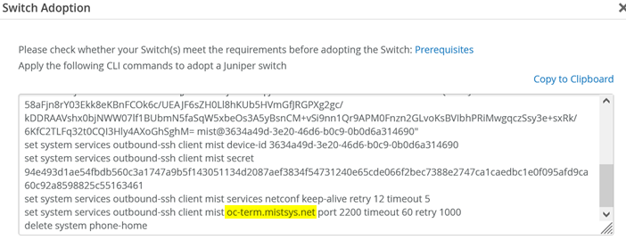
In the above example, the device is managed by FQDN
“oc-term.mistsys.net” so we can try to
open a telnet session to port 2200.
# test that a telnet session can be established
root> telnet oc-term.mistsys.net port 2200
Trying 52.53.57.207...
Connected to a4119aeb75a5342119e38dd3c475aff9-99130767d4e77d46.elb.us-west-1.amazonaws.com.
Escape character is '^]'.
^C
If the telnet session can be successfully established, it is a positive indication, but it does not guarantee full connectivity. This is because a test telnet session cannot replicate the complete connection process. Some firewalls that perform application-level inspection may still terminate the session later. Therefore, the next step is to verify that the session remains active and stable over time without unexpected interruptions.
# test that an outbound ssh session can be established
root> show system connections | match 2200 | match ESTA
tcp4       0      0  192.168.10.205.60913    52.53.57.207.2200  ESTABLISHED
# see for a longer time that the connection stays really up
root> show system connections | match 2200 | match ESTA | refresh 5
---(refreshed at 2024-02-29 14:49:49 UTC)---
tcp4       0      0  192.168.10.205.60913    52.53.57.207.2200  ESTABLISHED
---(refreshed at 2024-02-29 14:49:54 UTC)---
tcp4       0      0  192.168.10.205.60913    52.53.57.207.2200  ESTABLISHED
---(refreshed at 2024-02-29 14:49:59 UTC)---
tcp4       0      0  192.168.10.205.60913    52.53.57.207.2200  ESTABLISHED
---(refreshed at 2024-02-29 14:50:04 UTC)---
tcp4       0      0  192.168.10.205.60913    52.53.57.207.2200  ESTABLISHED
---(refreshed at 2024-02-29 14:50:09 UTC)---
tcp4       0      0  192.168.10.205.60913    52.53.57.207.2200  ESTABLISHED
---(refreshed at 2024-02-29 14:50:14 UTC)---
tcp4       0      0  192.168.10.205.60913    52.53.57.207.2200  ESTABLISHED
---(refreshed at 2024-02-29 14:50:19 UTC)---
tcp4       0      0  192.168.10.205.60913    52.53.57.207.2200  ESTABLISHED
---(refreshed at 2024-02-29 14:50:24 UTC)---
tcp4       0      0  192.168.10.205.60913    52.53.57.207.2200  ESTABLISHED
---(refreshed at 2024-02-29 14:50:29 UTC)---
tcp4       0      0  192.168.10.205.60913    52.53.57.207.2200  ESTABLISHED
---(refreshed at 2024-02-29 14:50:34 UTC)---
tcp4       0      0  192.168.10.205.60913    52.53.57.207.2200  ESTABLISHED
---(refreshed at 2024-02-29 14:50:39 UTC)---
tcp4       0      0  192.168.10.205.60913    52.53.57.207.2200  ESTABLISHED
---(refreshed at 2024-02-29 14:50:44 UTC)---
tcp4       0      0  192.168.10.205.60913    52.53.57.207.2200  ESTABLISHED
---(refreshed at 2024-02-29 14:50:49 UTC)---
tcp4       0      0  192.168.10.205.60913    52.53.57.207.2200  ESTABLISHED
---(refreshed at 2024-02-29 14:50:54 UTC)---
tcp4       0      0  192.168.10.205.60913    52.53.57.207.2200  ESTABLISHED
---(*more 100%)---[abort]
Switches Using CloudX as the Connection Towards Juniper Mist Cloud
To check if a switch can communicate with Juniper Mist cloud using CloudX:
- Run the below CLI commands on the switch:
user@switch> show version | match mist
JUNOS Mist Agent [v1.0.2205-2]
.
user@switch> show system connections | grep 443
tcp4       0      0  192.168.2.52.62957                            52.52.102.40.443                              ESTABLISHED
- To verify CloudX through the Juniper Mist portal, you can use
the steps below:
- Log in to the Juniper Mist portal (manage.mist.com).
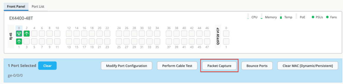
- Click Switches > switch name to go to the switch detail page.
- Click any port or a range of ports.
If CloudX is running, the Packet Capture button is enabled; otherwise, the button is grayed out.
You can also check if CloudX is enabled on multiple switches by using the Juniper Mist portal.
To do that, click Site > Switch Packet Captures > Add Switch.
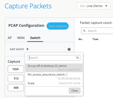
The switches listed here are all CloudX-enabled.
- Verify that Juniper Mist cloud daemon (mcd) and Junos Mist
daemon (jmd) is running.
The mcd process is responsible for enabling communication between the switch and the cloud. It maintains a secure WebSocket connection to the terminator in the cloud.
The jmd process is used for:
- Generating periodic statistics for the device.
- Applying device configuration.
- Gathering device events.
- Initiating device functions (such as packet capture and software updates).
- Returning results from requested functions (such as files and streamed data).
To verify that jmd and mcd are running, use the following CLIs:
user@switch> set cli screen-width 400
user@switch> start shell
% ps aux | grep jmd
root   21408   0.0  0.4 1246080  32200  -  S    Fri23      15:17.51 /var/run/scripts/jet/jmd -mcd-socket /var/run/mist_mcd.ipc
mist    3706   0.0  0.0   11136   2516  0  S+   07:14       0:00.00 grep jmd
%
%
% ps aux | grep mcd
root   21319   0.0  0.3 1242924  22256  -  I    Fri23       8:18.00 /var/run/scripts/jet/mcd
root   21408   0.0  0.4 1246080  32200  -  S    Fri23      15:17.53 /var/run/scripts/jet/jmd -mcd-socket /var/run/mist_mcd.ipc
mist    3708   0.0  0.0   11136   2516  0  S+   07:14       0:00.00 grep mcd
%
- Check the jmd and mcd logs for any errors by using the CLI
commands below. Typically, jmd logs show issues related to
configuration or stats. The mcd logs report issues related to the
connectivity between the switch and the cloud.
user@switch> show log jmd.log | last 10
[jmd] 2024/11/04 07:12:02 collector.go:850: total stats collection time = 10s
[jmd] 2024/11/04 07:12:02 app_states.go:355: app sending stats to mist cloud (26171 bytes)
[jmd] 2024/11/04 07:12:02 app_states.go:360: successfully sent ipc stats:
[jmd] 2024/11/04 07:12:02 app.go:282: processing app state "STEADY"
[jmd] 2024/11/04 07:12:12 app.go:339: sending ipc keep-alive
[jmd] 2024/11/04 07:12:22 app.go:339: sending ipc keep-alive
[jmd] 2024/11/04 07:12:32 app.go:339: sending ipc keep-alive
[jmd] 2024/11/04 07:12:42 app.go:339: sending ipc keep-alive
[jmd] 2024/11/04 07:12:52 app.go:339: sending ipc keep-alive
[jmd] 2024/11/04 07:12:52 collector.go:417: collecting periodic stats, interval 60
.
user@switch> show log mcd.log | last 10
[mcd] 2024/11/04 07:09:31 app.go:967: successfully sent msg to cloud: ep-telemetry
[mcd] 2024/11/04 07:10:02 ipc_server.go:414: rx ipc request: send cloud telemetry
[mcd] 2024/11/04 07:10:02 ipc_server.go:447: forwarding ipc telemetry to "junos-stats-" (26167 bytes)
[mcd] 2024/11/04 07:11:02 ipc_server.go:414: rx ipc request: send cloud telemetry
[mcd] 2024/11/04 07:11:02 ipc_server.go:447: forwarding ipc telemetry to "junos-stats-" (26171 bytes)
[mcd] 2024/11/04 07:12:01 app.go:967: successfully sent msg to cloud: ep-telemetry
[mcd] 2024/11/04 07:12:02 ipc_server.go:414: rx ipc request: send cloud telemetry
[mcd] 2024/11/04 07:12:02 ipc_server.go:447: forwarding ipc telemetry to "junos-stats-" (26171 bytes)
[mcd] 2024/11/04 07:13:02 ipc_server.go:414: rx ipc request: send cloud telemetry
[mcd] 2024/11/04 07:13:02 ipc_server.go:447: forwarding ipc telemetry to "junos-stats-" (26171 bytes)
- If jmd or mcd are not running for some reason, try restarting
them, as shown in the sample below.
user@switch> request extension-service restart-daemonize-app mcd
Extension-service application 'mcd' with pid: 92502 exited with return: -1
Extension-service application restarted successfully
Note:If you are using a Junos OS 22.4xx version, use the command
request
                extension-service daemonize-restart mcd
. - If the switch is not connecting to the cloud, check its reachability by using ping and curl tests. These tests will help you check if the required ports are allowed through the firewall.
The cloud endpoints are not set up to respond to ping tests; however, running a ping test will ensure that DNS resolves FQDN. Here is a sample ping test:
user@switch> ping jma-terminator-staging.mistsys.net
PING a8481a00030ad459aac15af07d5f2c5b-75855524.us-east-1.elb.amazonaws.com (3.210.247.53): 56 data bytes
^C
--- a8481a00030ad459aac15af07d5f2c5b-75855524.us-east-1.elb.amazonaws.com ping statistics ---
1 packets transmitted, 0 packets received, 100% packet loss
Here is a sample curl test:
user@switch> start shell
% curl -k https://jma-terminator.mistsys.net/test
Welcome to MIST
%
A valid response from the curl test proves that the jma-terminator in the Juniper Mist cloud is reachable. A lack of response or receipt of an error will indicate that the path between the switch and the cloud is blocking these ports, likely because of the firewall. The URLs used in the test are the same as those in firewall ports and differ between cloud instances.
Recover a Root Password
When you need to recover your root password, you must have a local console connection to the device and then follow the instructions here: https://www.juniper.net/documentation/us/en/software/junos/user-access/topics/topic-map/recovering-root-password.html.
Remove a Virtual Chassis
If you experience an issue with a Virtual Chassis setup, in some cases you may want to reset the entire system to factory settings. The CLI output below is based on the excellent demonstration video on YouTube.
# Login on first Switch and do
request virtual-chassis vc-port set interface vcp-255/1/0 disable
request virtual-chassis vc-port set interface vcp-255/1/1 disable
# added interfaces for EX4400
request virtual-chassis vc-port set interface vcp-255/1/2 disable
request virtual-chassis vc-port set interface vcp-255/1/3 disable
After entering the above commands on the primary switch, the primary switch will disconnect from the Virtual Chassis. Any further commands entered on this switch now go to the dedicated console port for this switch. The system will elect a new primary so try the next console port and repeat this process until all switches are finally disconnected from the Virtual Chassis and you have a dedicated console connection to all switches.
Next, access each switch and run the appropriate commands based on its member ID:
# delete any exiting pre-provision config first
edit
delete virtual-chassis pre-provision
commit and-quit
.
# When indicated by the ":1" member ID do the following
{master:1}
request virtual-chassis recycle member-id 0
request virtual-chassis renumber member-id 1 new-member-id 0
yes
.
# When indicated by the ":0" member ID do the following
{master:0}
request virtual-chassis recycle member-id 1
.
# In case the switch went into linecard-mode do this and then login again
request virtual-chassis reactivateAs a last step, ensure all your switches display “Master” as their role (ignore the master priority for now) and don’t see any other switch as connected before you leave the lab.
              show virtual-chassis
.
Virtual Chassis ID: 3d2d.5316.b4c3
Virtual Chassis Mode: Enabled
.                                                Mstr           Mixed Route Neighbor List
Member ID  Status   Serial No    Model          prio  Role      Mode  Mode ID  Interface
0 (FPC 0)  Prsnt    NX0216330306 ex3400-48t     128   Master*      N  VC
#
# Make sure there is no other memebr displayed here
#
.
Member ID for next new member: 1 (FPC 1)
Factory Reload of a Single Device
To get an EX Series Switch back to the initial factory configuration, execute the commands shown below and then afterwards, check that it can contact the Juniper Mist cloud.
              cli
              edit
              load factory-default
              delete chassis auto-image-upgrade
              set system root-authentication plain-text-password
# we are adding the below as a best practice
set system name-server 8.8.8.8
              set interfaces irb unit 0 family inet dhcp force-discover
              set interfaces vme unit 0 family inet dhcp force-discover
              commit and-quit
              show configuration | save /config/recovery.conf
# now check that you got a DHCP-lease and have a default route
show route
inet.0: 3 destinations, 3 routes (3 active, 0 holddown, 0 hidden)
Limit/Threshold: 32768/32768 destinations
+ = Active Route, - = Last Active, * = Both
0.0.0.0/0          *[Access-internal/12] 00:01:34, metric 0
                    >  to 10.33.33.1 via irb.0
10.33.33.0/24      *[Direct/0] 00:01:35
                    >  via irb.0
10.33.33.11/32     *[Local/0] 00:01:35
                       Local via irb.0
# test you can ping a site in the internet
ping 8.8.8.8
PING 8.8.8.8 (8.8.8.8): 56 data bytes
64 bytes from 8.8.8.8: icmp_seq=0 ttl=53 time=5.371 ms
64 bytes from 8.8.8.8: icmp_seq=1 ttl=53 time=5.175 ms
# test DNS working as well
ping www.google.com inet
PING www.google.com (142.251.32.36): 56 data bytes
64 bytes from 142.251.32.36: icmp_seq=0 ttl=112 time=24.966 ms
64 bytes from 142.251.32.36: icmp_seq=1 ttl=112 time=18.031 ms
64 bytes from 142.251.32.36: icmp_seq=2 ttl=112 time=9.661 ms
64 bytes from 142.251.32.36: icmp_seq=3 ttl=112 time=8.440 ms
Check the Device RTC Clock When Having ZTP Issues.
The longer a device remains in storage, the more its internal clock can drift. During the phone-home ZTP process, the device verifies the server certificate, and if the local clock is significantly incorrect—such as being set to 1970—the verification will fail. As a best practice, an NTP server should always be used to synchronize the device’s time. The Juniper Mist cloud automatically configures this once the device is under its management. However, during the initial factory default state when starting ZTP, this configuration is not yet in place. If this issue occurs, you can either configure an NTP server or manually set the system clock, as shown below:
# optional: set a local NTP server of this lab
cli
edit
set system ntp boot-server 216.239.35.0
set system ntp server 216.239.35.0
commit and-quit
# check current time else ZTP CA-Certificates may be rejected
show system uptime
Current time: 2024-01-08 14:16:34 UTC
.
.
# In case the date is below Year 2024 manually adjust the local time
# set date YYYYMMDDhhmm.ss
# or check if you already have enough connctivity to do that via our lab ntp
# set date ntp 216.239.35.0
restart phone-home-client
Phone home client daemon signalled but still running, waiting 28 seconds more
Phone home client daemon still running, sending another terminate signal
Phone home client daemon started, pid 7197
Juniper Access Point Attached to EX Series Switch
Here, we integrate the next element to complete the branch installation which is attaching the AP to the switch to support wireless clients.
Pre-Conditions That Must Be Met for AP Onboarding
To be able to execute this lab, we assume that the following conditions are met:
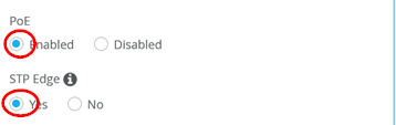
- The AP is cabled to our EX Series Switch and has power (through an external power supply or through PoE).
- If PoE is being used, the switch must have sufficient available PoE power and support at least IEEE 802.3af or IEEE 802.3at standards, depending on the AP model.
- LLDP should be enabled on switches and routers to assist with troubleshooting, although it is not strictly required.
- You have completely followed the instructions from the above
chapters as those include instructions for the following:
- A DHCP server is configured for the AP management VLAN 1033 subnet 10.33.33.0/24 in this branch. In our example, that is done on the WAN router.
- An additional VLAN 1088 subnet 10.88.88.0/24 is used for WLAN clients.
- An additional VLAN 1099 subnet 10.99.99.0/24 is used for wired clients.
- On the WAN router, a LAG is formed to the switch containing native VLAN 1033 and VLANs 1088 and 1099 as trunk. Keep in mind that without further changes, the native VLAN from the uplink gets assigned to VLAN 1 on the switch where irb.0 for in-band management is assigned. Providing that management VLAN then to a downstream device such as an AP needs then to reference this VLAN 1.
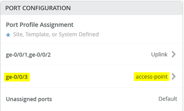
- On the port where the switch is attached, the default VLAN 1 is native and VLAN 1088 is trunked. We did not add 1099 for wired clients again as the port does not need to support it.
- The WAN router must implement some form of source NAT on the WAN interfaces to allow management traffic towards the Juniper Mist cloud.
Below is just a reminder about the minimal configuration on the switch (apart from the uplink):
How to Claim APs to an Organization
APs can be claimed to any organization by using either an activation code, claim code, or QR code.
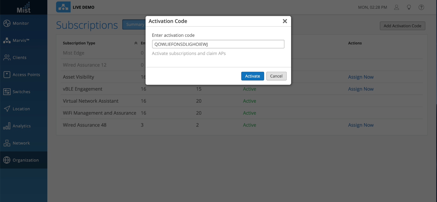
Activation Code
Whenever you order APs, our Sales Operations team will send you an activation code which can be used for claiming the APs and subscriptions as per the order. You can use this activation code to claim APs in one go. To claim the APs, go to the Organization > Subscriptions page and select Add Activation Code button in the upper-right corner. Once the activation code is added and activated, all the APs will automatically get claimed to the organization. You can see the list of APs on the Inventory page (Organization > Inventory).
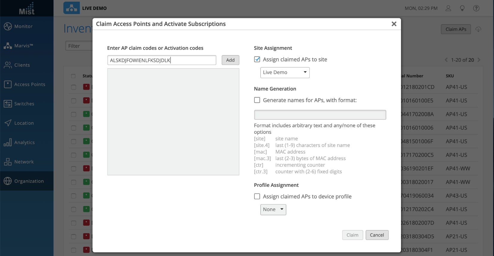
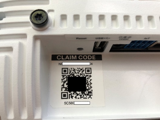
AP Claim Code
You can individually claim APs to your organization by navigating to Organization > Inventory > Claim APs and entering in the claim code found on the back of each AP.
AP QR Code
Using our MistAI mobile app, you can scan the QR code printed on the back of our APs to claim APs to your organization. Our app is compatible with both iOS and Android devices. Read more about it here: https://www.mist.com/documentation/mist-ai-mobile-app/
Where Can I Get the Claim Codes for the APs in My Organization?
The claim code of the AP is written on the backside of the AP where the QR code of the AP is printed.
Troubleshoot: Bringing the AP Online as “Connected” Into the Inventory
We assume in this step you have used any of the methods above to claim the AP into the inventory. When you refresh the browser window after 3-5 minutes, the AP should appear automatically in the “Connected” state in the Inventory such as seen in the figure below:
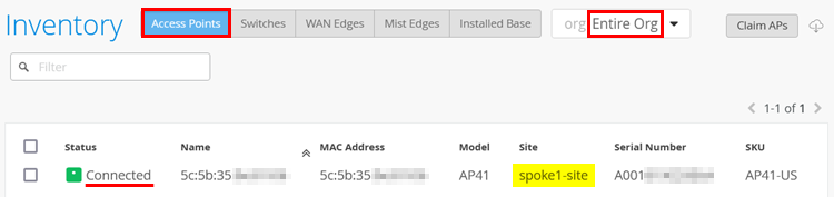
If your AP shows as “Connected”, you can skip this section, as the following instructions cover troubleshooting if the AP is not connecting.
The troubleshooting of Juniper APs is explained in detail here:
https://www.mist.com/documentation/category/troubleshooting/.
This section will focus on what to troubleshoot on the EX Series
Switch side to help bring the AP into the
“Connected” state in the Inventory.
If the AP is not assigned to a site, it will always appear in the “Disconnected” state irrespective of its connectivity to the cloud. Remember that along with claiming the AP, assigning the AP to a site is mandatory.
If you are local to the site, check the AP’s status LED since its blinking code may indicate an error.
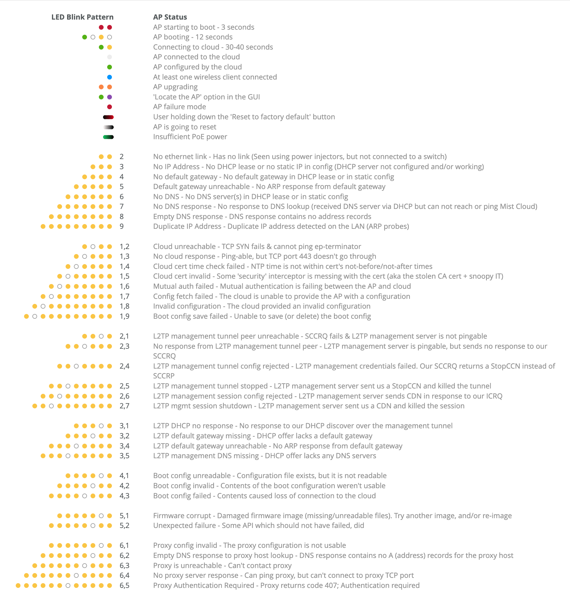
The first thing to do is to understand the source of the error by viewing the AP’s status LED. If you can’t see the LED on the AP, reboot it. If the AP is powered by PoE, then you can do that using one of two methods:
- Use the Bounce Ports option on the portal. Selecting the port where the AP is attached opens a pane where you can directly select to bounce a particular port which will also power cycle the attached AP.
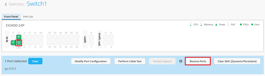
You will see a new window with information about the bounce port status as shown in the figure below:
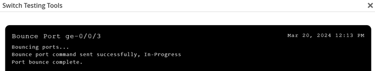
Bouncing a port may take several minutes since two Junos OS configuration commits must happen as part of the process.
- Change the PoE interface configuration using remote shell (This
option is not recommended).
cli
edit
set poe interface ge-0/0/3 disable
commit
# wait >20seconds
delete poe interface ge-0/0/3 disable
commit and-quit
exit
If the AP is powered by an external power supply, then you must ask someone to unplug it for a while and then power it on again. The AP has no console connection like the switches.
The next step is to use a remote console to the switch to review items such as:
- Is the port that the AP is connected to showing as “Up”?
- Is the port that the AP is connected to correctly configured and forwarding packets?
- Does the MAC address of the AP appear on the expected port?
- Do you see the AP appearing as an LLDP neighbor?
- Assuming the AP is powered by PoE, what’s the actual power draw?
The following example output shows an AP that is attached to interface ge-0/0/3:
- Check if the port is administratively
“
up” and a physical link detected.root@Switch1> show interfaces terse Interface Admin Link Proto Local Remote ge-0/0/0 up down ge-0/0/0.0 up down eth-switch ge-0/0/1 up up ge-0/0/1.0 up up aenet --> ae0.0 ge-0/0/2 up up ge-0/0/2.0 up up aenet --> ae0.0 ge-0/0/3 up up ge-0/0/3.0 up up eth-switch ge-0/0/4 up down ge-0/0/4.0 up down eth-switch . - Then, check that the port is in forwarding mode and that it is
configured with the expected VLAN (the default VLAN in this
example) and is in access mode. Also, verify that the VLAN assigned
is the same VLAN that the WAN router uses for DHCP lease handouts
for AP management.
root@Switch1> show ethernet-switching interface ge-0/0/3 Routing Instance Name : default-switch Logical Interface flags (DL - disable learning, AD - packet action drop, LH - MAC limit hit, DN - interface down, MMAS - Mac-move action shutdown, AS - Autostate-exclude enabled, SCTL - shutdown by Storm-control, MI - MAC+IP limit hit) Logical Vlan TAG MAC MAC+IP STP Logical Tagging interface members limit limit state interface flags ge-0/0/3.0 32768 0 tagged WLAN-Client 1088 32768 0 Forwarding tagged default 1 32768 0 Forwarding untagged - Next, check if the MAC address (also printed on the QR code) of
the AP appears on the switch’s interface as expected.
root@Switch1> show ethernet-switching table
MAC flags (S - static MAC, D - dynamic MAC, L - locally learned, P - Persistent static, C - Control MAC
           SE - statistics enabled, NM - non configured MAC, R - remote PE MAC, O - ovsdb MAC)
Ethernet switching table : 2 entries, 2 learned
Routing instance : default-switch
    Vlan                MAC                 MAC         Age    Logical                NH        RTR
    name                address             flags              interface              Index     ID
    default             5c:5b:35:be:81:06   D             -   ge-0/0/3.0             0         0
    default             ee:38:73:9a:d4:a5   D             -   ae0.0                  0         0
At this point, it is appropriate to check the port authorization status of the AP as well. Sometimes it is intended that the AP authorizes itself to the switch it is attached to and sometimes this is not required, and someone accidentally applies a port profile with authentication enabled.
- Next, check if you see the AP’s MAC address appearing as
an LLDP neighbor Chassis ID. The port info may be different based
on the AP model you have; however, the system name may help you
determine more about the state of the AP:
- When no LLDP system name is reported, then the AP has a connection issue. For example, it cannot receive a DHCP lease.
- When the LLDP system name is “Mist”, like in the example below, then the AP is usually up but not assigned to an inventory.
- When the LLDP system name is the MAC address of the AP or the inventory name, then it should already be in the “Connected” state in the inventory of your organization and you can start applying more configuration.
root@Switch1> show lldp neighbors Local Interface Parent Interface Chassis Id Port info System Name ge-0/0/1 ae0 ec:38:73:9a:d5:24 ge-0/0/5 spoke1 ge-0/0/2 ae0 ec:38:73:9a:d5:24 ge-0/0/6 spoke1 ge-0/0/3 - 5c:5b:35:be:81:06 ETH0 Mist - Should you have PoE running on the switch, you should also
check the power consumption of the AP. The PoE mode negotiated
depends on the AP model (usually 802.3af on 802.3at) and can be
verified in the datasheet. Depending on the configuration state and
radio usage, you should see differences in the actual “power
consumed” report.
root@Switch1> show poe interface
.
.
root@Switch1> show poe interface ge-0/0/3
PoE interface status:
PoE interface                :  ge-0/0/3
Administrative status        : Enabled
Operational status           :   ON
Power limit on the interface : 19.5W (L)
Priority                     : High
Power consumed               : 7.3W
Class of power device        :        4
PoE Mode                     :   802.3at
  (L) LLDP-negotiated value on the port.
- The following checks should be done on the WAN router. In our
example, we use a remote console session to an SRX Series Firewall
acting as WAN router. You should look for the DHCP lease requests
from the AP and verify that you see two sessions towards port 443
for TCP/UDP towards the Juniper Mist cloud as shown in the example
below.
root@spoke1> show dhcp server binding
IP address        Session Id  Hardware address   Expires     State      Interface
10.33.33.12       3           04:5c:6c:6b:13:42  54553       BOUND      ae0.0
10.33.33.15       6           5c:5b:35:be:81:06  48923       BOUND      ae0.0
.
root@spoke1> show arp interface ae0.0
MAC Address       Address         Name                      Interface               Flags
04:5c:6c:6b:13:42 10.33.33.12     10.33.33.12               ae0.0                   permanent
5c:5b:35:be:81:06 10.33.33.15     10.33.33.15               ae0.0                   permanent
Total entries: 2
.
root@spoke1> show security flow session source-prefix 10.33.33.15
Session ID: 34359960425, Policy name: 01_Internet/20, State: Stand-alone, Timeout: 60, Valid
  In: 10.33.33.15/40267 --> 44.204.233.81/443;udp, Conn Tag: 0x0, If: ae0.0, Pkts: 45026, Bytes: 8408428,
  Out: 44.204.233.81/443 --> 192.168.173.145/23463;udp, Conn Tag: 0x0, If: ge-0/0/0.0, Pkts: 5524, Bytes: 407857,
.
Session ID: 34359962715, Policy name: 01_Internet/20, State: Stand-alone, Timeout: 1794, Valid
  In: 10.33.33.15/37165 --> 54.144.163.241/443;tcp, Conn Tag: 0x0, If: ae0.0, Pkts: 8997, Bytes: 4866046,
  Out: 54.144.163.241/443 --> 192.168.173.145/28185;tcp, Conn Tag: 0x0, If: ge-0/0/0.0, Pkts: 5063, Bytes: 421001,
Total sessions: 2
When Do We Use Dynamic Port Profiles and When Do We Use a NAC Infrastructure?
Port profiles can be assigned statically or dynamically based on the detected wired client. Both have their advantages and downsides which we do not discuss here. When you choose a dynamic approach, an EX Series Switch managed by Juniper Mist cloud offers the following two options:
- Dynamic VLAN/filter assignment by RADIUS/NAC infrastructure. In
this case, you usually configure a static VLAN into a quarantine
network that has limited access to the Internet and corporate
resources and assign it as default VLAN in the port profile to be
used. This is for fall through configuration in case the RADIUS
authentication fails and you can’t afford all clients not
being able to access the network. You then also activate 802.1x
authentication for the port or 802.1x authentication and MAB (MAC
address-based authentication). When the wired client then logs in
to the port, the RADIUS server receives several attributes about
the client such as:
- Authentication parameters like a username or a certificate.
- Switch name and port.
- Wired client MAC address.
The backend RADIUS server can include several authorization parameters in the access-accept message, specifying what should be dynamically assigned to the port, such as:
-
- A single access VLAN for the client.
- Several VLANs where one is native, and the others are tagged VLANs. This is also called colorless port assignment in the literature. This is usually used when the attached device is an AP.
- A filter ID string that can be used to apply the following:
- An ACL-based filter for local firewalling.
- A GBP tag to be assigned to a wired client. (Only applicable in IP Clos fabrics. This option is not relevant for this JVD discussing branch designs).
- Dynamic Port Configuration (DPC) by
Juniper Mist cloud for colorless ports. As the name indicates, this
feature is limited to EX Series Switches which are managed by
Juniper Mist cloud and does not work elsewhere. When a user
connects a client device to a switch port with this feature
enabled, the switch identifies the device and assigns a suitable
port profile to the port. Dynamic port profiling utilizes a set of
device properties of the client device to automatically associate
pre-configured port and network settings to the interface. You can
configure a dynamic port profile based on the following parameters:
- LLDP System Name
- LLDP Description
- LLDP Chassis ID
- Radius Username
- Radius Filter ID
- MAC (Ethernet MAC address) also MAC OUI.
We recommend using dynamic VLAN/filter assignment by RADIUS/NAC infrastructure whenever possible. Especially when using Juniper Mist Access Assurance as your RADIUS/NAC infrastructure where this becomes an easy to manage task.
Let’s review these use cases and how they work:
-
Use case 1: RADIUS/NAC Infrastructure present in the network
Usually – there are two goals with enabling authentication on a port:
-
- Making the system zero trust
- Assign the devices to their relevant network segments.
-
In networks utilizing a RADIUS infrastructure, we recommend all ports be set to an access port with a dot1x + MAB port profile enabled. We rely on RADIUS transactions to get the network/VLAN assignments as well as assign the ports as access or trunk based on the use case. Clients could be a combination of devices that are capable of dot1x (802.1x EAP-authenticated supplicants) or all device MAC addresses are available in the RADIUS database. Please be sure to configure RADIUS servers with enhanced timers in the switch template. (Enhanced timers reduce the default fallback time from dot1x to MAB from ~120-180 seconds to ~10-15 seconds, which is highly recommended for a good client experience).
Let’s discuss the different use cases for return attributes (AVP) from RADIUS that we recommend being sent as part of the access-accept message:
- Clients that need to be assigned to a specific VLAN while the
port remains an access port. Here, you use the
AVP=Tunnel-Private-Group-ID. See the example configuration below:
001094001123 Cleartext-Password := "001094001123" Tunnel-Type = VLAN, Tunnel-Medium-Type = IEEE-802, Tunnel-Private-Group-ID = "VLAN1099", - Clients that need to be assigned to multiple VLANs and need to
be moved to a trunk port. Here, you use the AVP=Egress-VLAN-ID or
Egress-VLAN-Name. See the example configuration below:
# 4Byte tagged VLAN = 0x31+<000000padding>-<VLAN-ID in Hex> # 4Byte untagged VLAN = 0x32+<000000padding>-<VLAN-ID in Hex> 001094001177 Cleartext-Password := "001094001177" Tunnel-Type = VLAN, Tunnel-Medium-Type = IEEE-802, Egress-VLANID += 0x32000001, Egress-VLANID += 0x31000440, . # first char of string 1 = Tagged , 2 = native/untagged 001094001144 Cleartext-Password := "001094001144" Tunnel-Type = VLAN, Tunnel-Medium-Type = IEEE-802, Egress-VLAN-Name += "2default", Egress-VLAN-Name += "1VLAN1088", - Clients that need to be assigned to a policy as
firewall-filter/ACL (In addition to either of the above two AVPs).
Here, you use the AVP=Filter-Id.
001094001142 Cleartext-Password := "001094001142"
    Tunnel-Type = VLAN,
    Tunnel-Medium-Type = IEEE-802,
    Tunnel-Private-Group-ID = "1099",
    Filter-Id = "filter1"
Keep in mind that before you can use a particular filter ID, you must create a filter on the switch itself. Here is an example using additional CLI:
set firewall family ethernet-switching filter filter1 term supplicant1 from source-mac-address 00:10:94:00:11:42
set firewall family ethernet-switching filter filter1 term supplicant2 from source-mac-address 00:10:94:00:11:66
set firewall policer p1 if-exceeding bandwidth-limit 1m
set firewall policer p1 if-exceeding burst-size-limit 1k
set firewall policer p1 then discard
set firewall family ethernet-switching filter filter1 term supplicant1 then cosunt counter1
set firewall family ethernet-switching filter filter1 term supplicant1 then policer p1
set firewall family ethernet-switching filter filter1 term supplicant2 then count counter2
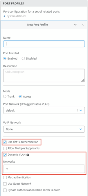
- Another way is to assign the Dynamic VLAN based on a port profile but still requiring the authentication through RADIUS at least to be performed for the wired client. Hence, the RADIUS server in this case is not required to send back any of the above-mentioned RADIUS AVPs as part of the final access-accept message. Only the access-accept message is required and the VLAN configuration will be derived from the port profile. The figure below shows where this optional configuration can be made.
We do not recommend adding DPC in any of the above scenarios, hence do not turn on DPC on any of the ports in this scenario as well. This is the most preferred scenario in case you have a RADIUS/NAC infrastructure.
-
Use case 2: Usage of RADIUS/NAC infrastructure but augmenting some devices with DPC for the reasons mentioned below:
All of the above AVPs listed in use case 1 still hold true. Juniper DPC, however, extends functionality by using LLDP information and MAC OUI (the vendor portion of a MAC address) as identifiers for port configuration. This level of identification is typically not available when relying solely on a traditional RADIUS or NAC-based management system.
Motivation for this approach:
-
- Avoid adding a lot of MACs (APs and cameras are usually volume devices) to the RADIUS user database and use LLDP and MAC OUI instead.
- Reduce the cost of RADIUS/NAC infrastructure, since it involves client count.
-
Juniper recommends enabling an additional layer of security, such as 802.1X or MAB, when using VLAN assignment through DPC on certain ports. The remaining ports should continue to use 802.1X or MAB for authentication, but without incorporating DPC.
In case you cannot predict where selected devices will be plugged in to the network, all ports need to enabled for DPC and 802.1x or MAB which is the less recommended approach.
For both use case 1 and use case 2, when 802.1x and MAB are enabled on all ports, it is critical to note that no MAC addresses will be learned until the authentication is successful. Hence, DPC using MAC-based rules will not work and should not be configured. We only recommend using DPC with LLDP-based rules when ports are enabled for 802.1x and MAB.
- Use case 3: No RADIUS/NAC infrastructure, DPC + static
assignment of port profiles.
- In the absence of a RADIUS/NAC Infrastructure, DPC could be used either with LLDP or MAC-based rules to provision ports. The preferred approach is if one is aware of the ports that are allocated for DPC eligible devices, one should enable DPC only on those ports. The rest of the ports are to be statically assigned.
- The less preferred approach is if one is not aware of the ports where DPC eligible devices will be plugged in, enable DPC on all ports.
- We also recommend the default profile where the DPC is enabled, to be pointing to a dummy (or at least a quarantine) VLAN, so no devices get IPs when they are plugged and do not match any DPC rules.
Avoid using DPC if the port experiences a large number of port flaps. Each port flap will trigger a configuration change on the switch (Junos OS commit). In such a case, it is better to apply dynamic VLAN configuration through RADIUS.
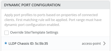
The figure below illustrates an example where DPC identifies a Juniper AP using the vendor MAC OUI part of the LLDP chassis ID.
.png)
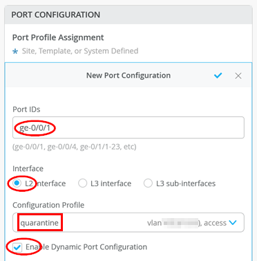
Do not forget that you must activate DPC for the port by using the checkbox as indicated by the image below:
It takes a couple of minutes for a port profile to be applied to a port after a client is recognized, and a couple of minutes after that for the port profile assignment status to appear on the portal. In case of switch reboots or a mass link up or down event affecting all ports on a switch, it takes approximately 20 minutes for all the ports to be assigned to the right profile (assuming that DPC is enabled on all ports).
When the Switch Utilizes CloudX Towards Juniper Mist Cloud
The following changes to the operation of DPC need to be kept in mind when the Switch uses CloudX for communication towards the Juniper Mist cloud.
- CloudX leverages an ephemeral database in Junos for DPC and the port bounce feature instead of the conventional static configuration database that is usually used.
- Any interfaces enabled with DPC are moved to an ephemeral database from the static configuration database. This includes any Spanning Tree Protocol (STP) configuration as well.
- Ephemeral database commits are faster. The commits take 1-2 seconds even on a large VC compared to the static configuration database.
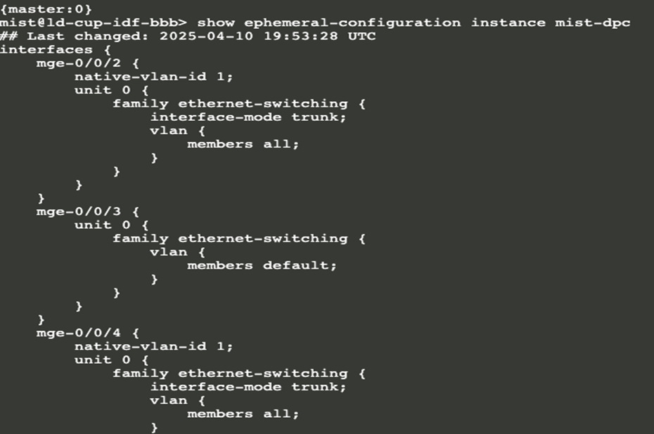
- When looking at the static configuration database, you will not see the changes made
in the ephemeral database. So, do not get confused thinking your DPC configuration was not
applied. To review the configuration in the ephemeral database, run the following Junos OS
CLI commands through a console or remote shell session as shown below
show
              ephemeral-configuration instance mist-dpc
Using a combination of DPC and 802.1X configuration through additional Junos OS CLI commands is not supported. When CloudX is enabled, DPC relies on the ephemeral database, and mixing it with static configuration from additional CLI results in inconsistencies between the static settings and the interface configurations stored in the ephemeral database.
Configure DHCP Snooping for Switches
DHCP snooping enables a switch to examine all the DHCP traffic initiated from the untrusted ports on the network. When DHCP snooping is enabled on a VLAN, the system examines DHCP messages sent from untrusted hosts associated with the VLAN and extracts their IP addresses and lease information. This information is used to build and maintain the DHCP snooping database. Only hosts that can be verified using this database are allowed access to the network. More detailed information about this security feature and how it operates can be found here https://www.juniper.net/documentation/us/en/software/junos/security-services/topics/concept/port-security-dhcp-snooping-els.html.
By default, access ports are treated as untrusted ports and trunk ports are treated as trusted ports.
There are three places where you can configure the DHCP Snooping/ARP Inspection/IP Source Guard in the portal:
- Switch Device Details page.
- Site > Switch Configuration page
- Organization > Switch Templates.
Configuration is applied in the following order of priority: first from the Switch Device Details page, followed by the Site > Switch Configuration page, and finally from the Organization > Switch Templates, which has the lowest priority.
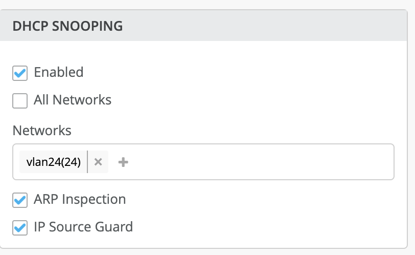
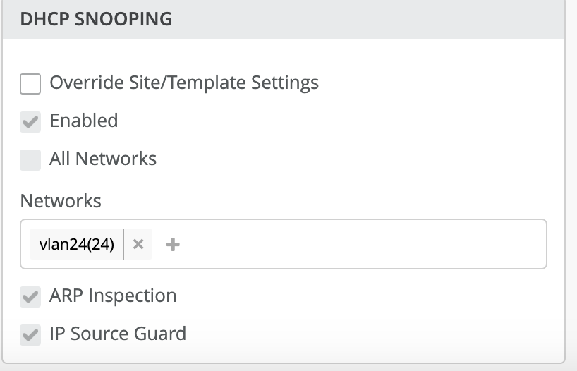
Below is an example where you can enable the above configuration for a single network. There are two options you can enable for all networks / single network as per your requirement.
In the example below, we are enabling DHCP snooping for a single network > Vlan24 (vlan-id-24).
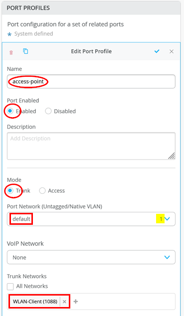
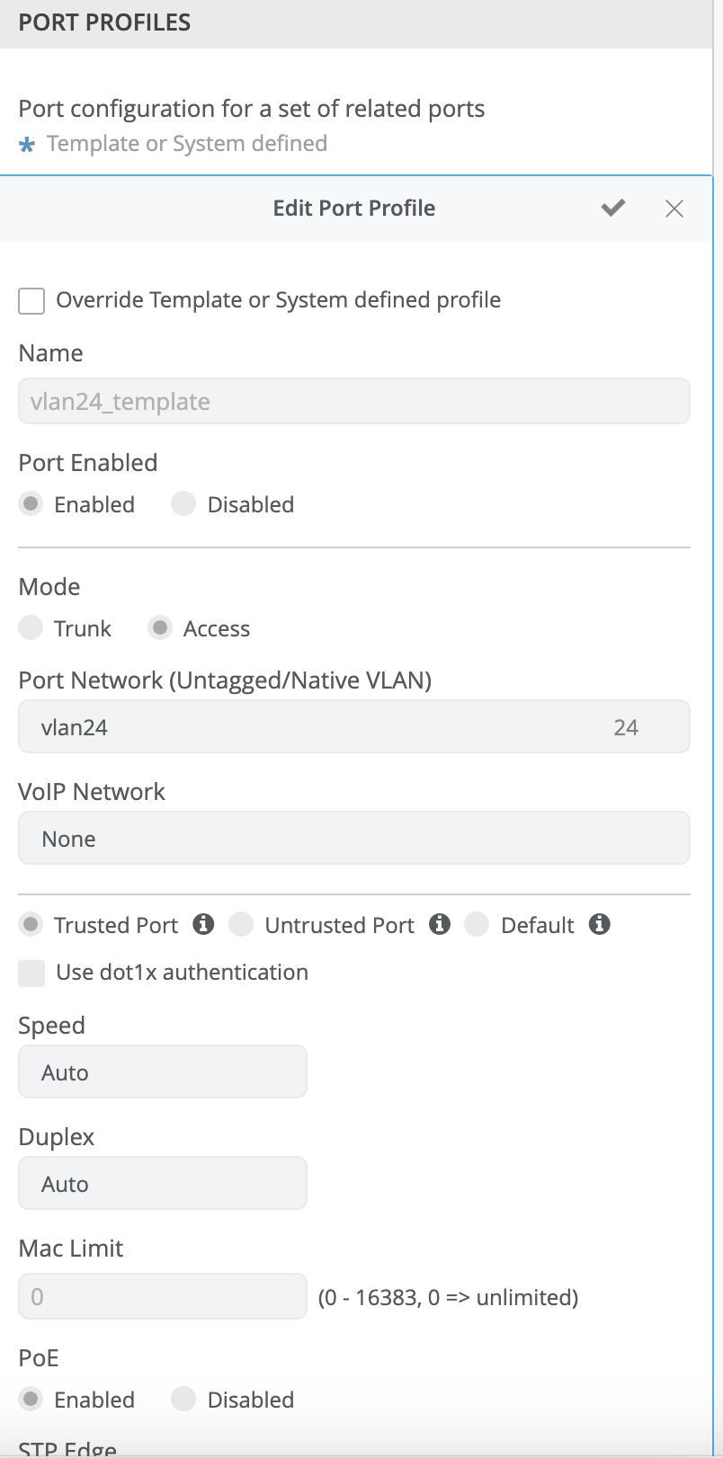
The VLAN must exist on the switch for the configuration to take effect. For this reason, the port needs to be associated with a port profile. In an access port profile, you can specify whether the port is trusted or untrusted; if this setting is not defined, it defaults to the standard behavior (untrusted). The port network can be configured as either a standard data network or a VoIP network. By default, trunk ports are always considered trusted.
In the example below, we make the access port trusted:
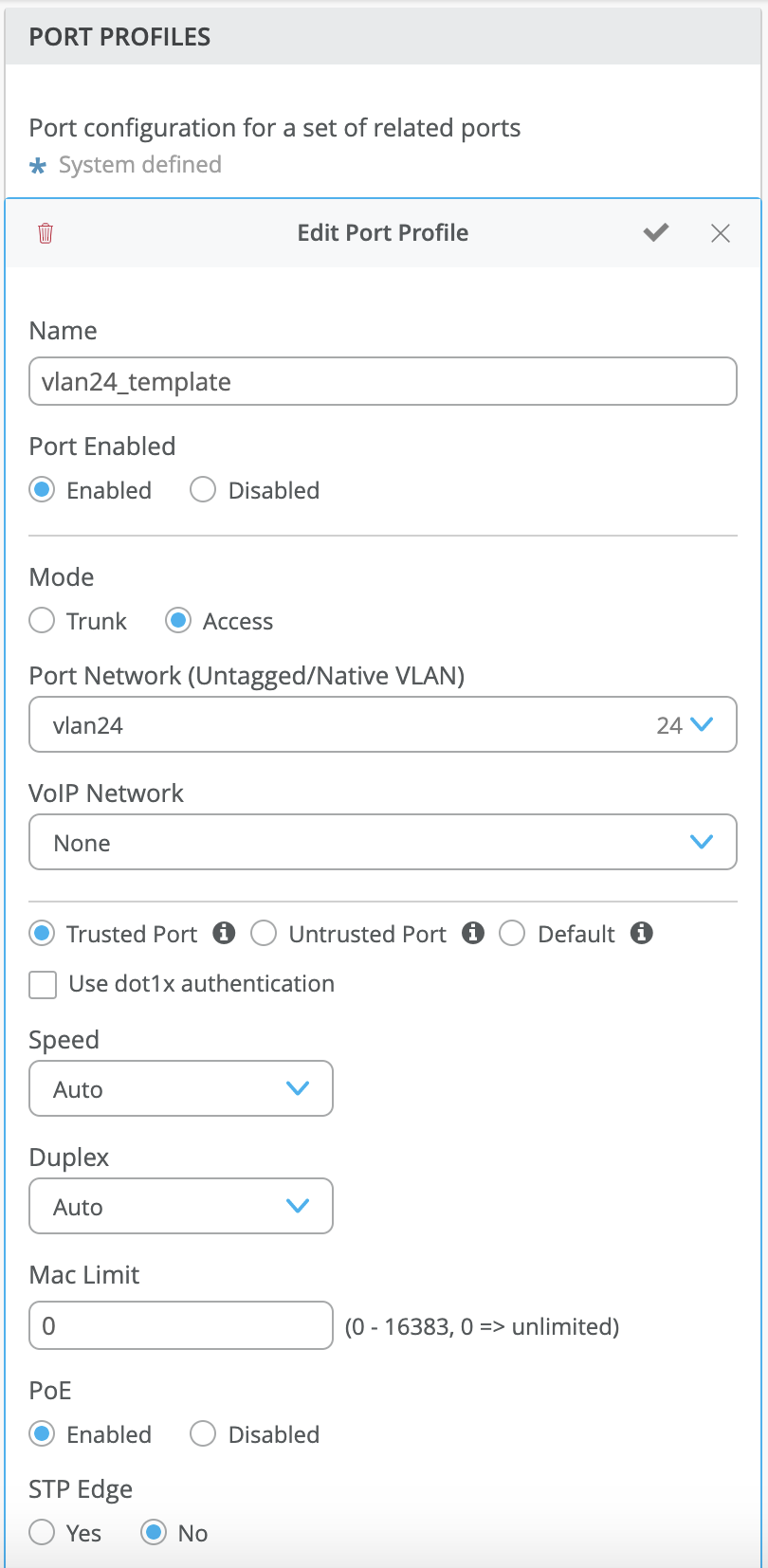
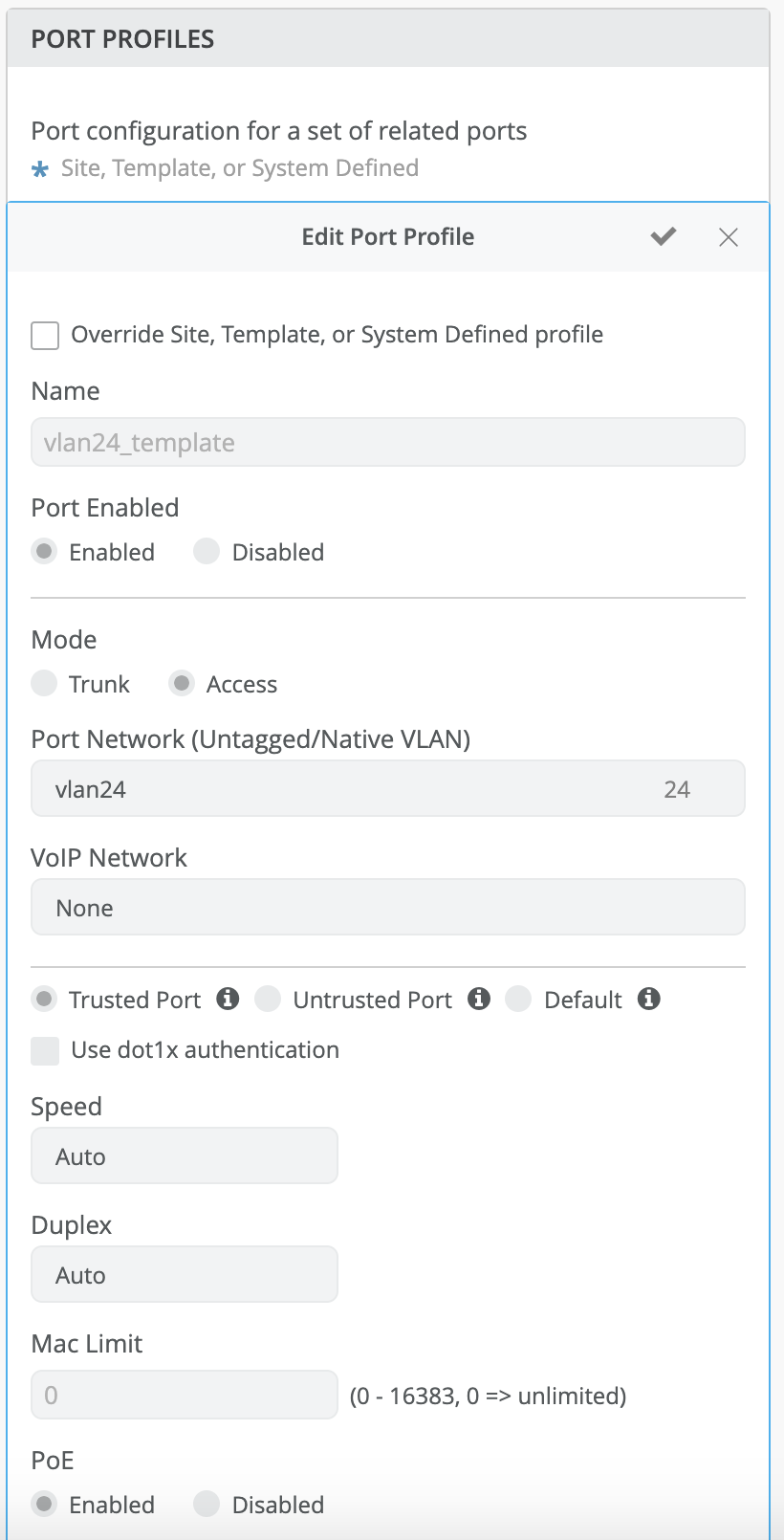
The port profile to the port would be as below:
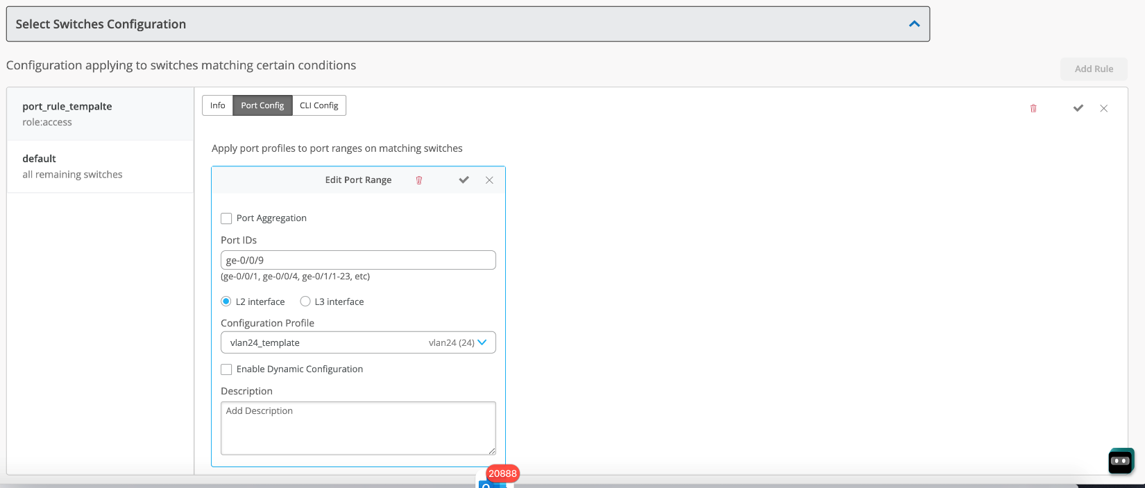
We have the option for the override site/template settings for DHCP snooping from the site settings and device settings:
Site settings:
We have the options for overriding the trusted/untrusted/default options for port profile from the site settings and device settings.
Site settings:
Device settings:
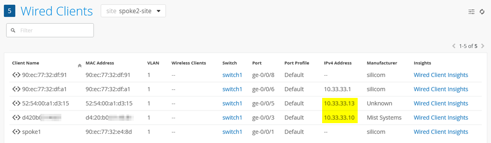
Enabling DHCP snooping will allow the Juniper Mist cloud to show IP Address information when reviewing the clients table. Unlike a campus fabric deployment, the switch has no VRF configuration and is a pure Layer 2 forwarder. Hence, the switch is usually not enabled for ARP resolution as a default gateway and would not be able to gather such information automatically and report it to the Juniper Mist cloud.
Command to configure DHCP snooping:
set vlans default forwarding-options dhcp-security
Command to check the DHCP snooping table locally on the switch like in the example below:
              show dhcp-security binding
IP address        MAC address         Vlan     Expires State   Interface
10.33.33.10       d4:20:b0:xx:yy:zz   default  0       REQUESTING ge-0/0/3.0
10.33.33.13       52:54:00:a1:d3:15   default  0       BOUND   ge-0/0/5.0